Article citation information:
Warczek,
J., Gąszczak, A. Analysis of
procedures for adapting the technical parameters of a propeller drive with
an electric motor – a case study. Scientific
Journal of Silesian University of Technology. Series Transport. 2026, 131, 253-273. ISSN: 0209-3324. DOI: https://doi.org/10.20858/sjsutst.2026.131.15
Jan WARCZEK[1],
Aleksander GĄSZCZAK[2]
ANALYSIS OF PROCEDURES FOR ADAPTING THE TECHNICAL PARAMETERS OF A
PROPELLER DRIVE WITH AN ELECTRIC MOTOR – A CASE STUDY
Summary. Selecting a propeller for a non-standard powerplant
poses a significant challenge in aircraft design, particularly when engine
parameters deviate from conventional aviation standards. This paper presents a
methodology for assessing the compatibility of a three-blade Clark-Y airfoil propeller with selected propulsion configurations
using aerodynamic and computational relationships. The approach enables
verification of its applicability in non-standard design cases and supports
flexible implementation across diverse propulsion systems. The method, its
application, and potential use in engine-propeller integration are presented.
Keywords: propeller,
electric propulsion, propeller selection, aerodynamic analysis
1. INTRODUCTION
The selection of a propeller for a propulsion
unit constitutes a complex problem in which the engine characteristics define
the admissible operating points, while the geometry and settings of the
propeller determine the power absorption, generated thrust, and efficiency as a
function of forward velocity. These relationships may be described analytically
using classical theoretical approaches based on momentum theory, blade element
theory, and their extensions in the form of combined methods and vortex models
[2, 9, 14]. These approaches form the foundation of both design and application
calculations, enabling a quantitative assessment of the influence of geometric
parameters and operating conditions on propeller characteristics.
The parameterization of propeller geometry,
including diameter, number of blades, twist, and aerodynamic profile, has a
direct impact on the load distribution and efficiency within a given range of
advance ratio [6, 10]. The properties of aerodynamic airfoils,
commonly used in aviation, remain an essential element of modeling
both in classical approaches and in the interpretation of numerical calculation
results. On this basis, numerous design procedures have been developed in which
blade geometry constitutes the primary decision variable [1].
A significant portion of existing methods
focuses on the design or optimization of propeller geometry, where the
distribution of twist and chord along the blade is selected to maximize
efficiency or satisfy a specified energy criterion at a given operating point
[10, 11, 17, 25]. These approaches are sometimes extended to include specific
conditions, such as operation at high altitude or in environments with reduced
air density, characteristic of high-altitude and stratospheric platforms [20,
21]. In such cases, the propeller geometry is strictly subordinated to defined
operating conditions, and the operating point is treated as a design element.
In real applications, however, propeller
operating conditions deviate from ideal assumptions. Performance
characteristics are influenced by aerodynamic interactions, including the
interaction of the propeller slipstream with the wing or fuselage, the cooperation
of multiple propellers, and unsteady flow conditions in multirotor systems [15,
19, 22]. Changes in effective inflow velocity and load distribution lead to
significant differences between characteristics calculated for an isolated
propeller and those observed under real operating conditions [16].
Additionally, acoustic and diagnostic aspects are analyzed,
indicating the multidimensional nature of propeller selection criteria in
engineering practice [17, 18].
Classical propeller selection procedures were
developed primarily with respect to internal combustion engines. Analyzes concerning fixed-pitch propellers for low-power
units organize the relationships between shaft power, rotational speed, and the
selection of diameter and pitch, while also indicating limitations resulting
from engine characteristics [6, 7]. This issue also appears in multirotor
applications with internal combustion propulsion, where it affects the
stability and efficiency of the entire system [12].
In the case of electric propulsion systems, the
emphasis shifts toward different constraints. The characteristics of electric
motors, including parameters such as efficiency, torque limitations, and
maximum rotational speed, combined with the properties of controllers and
energy sources, determine the range of achievable propeller operating points
[8, 13, 23]. Analyzes conducted for small electric
aircraft, UAV platforms, and VTOL configurations show that propeller selection
is a compromise and involves the simultaneous evaluation of thrust, efficiency,
and power margin across different phases of flight [3, 4, 5]. In this context,
selection procedures based on available propeller and motor characteristics are
being developed, without the need to design a new blade geometry [5, 13].
The above considerations lead to a clear
distinction between propeller geometry design and the selection of operating
parameters for a propeller with known geometric characteristics. In many design
applications, the problem reduces to determining rotational speed and blade
setting angle and consequently selecting the range of advance ratio and
propeller efficiency, for a given number of blades with specified aerodynamic
profiles and diameter, taking into account the known characteristics of the
propulsion unit [2, 9, 7]. Iterative procedures developed for electric propulsion
systems also exist, linking propeller selection with the motor, controller, and
energy source, focusing on the evaluation of achievable operating points and
power balance [23, 24]. In parallel, formal multi-criteria selection approaches
are being developed, in which relationships between thrust, efficiency, and
power consumption are analyzed, while emphasizing the
importance of low computational cost methods in parametric analyses [17, 24,
25].
In this study, assumptions were adopted in which
the starting point consists of the characteristics of the propulsion unit
considered for an electric motor and a propeller with defined geometry. The
subject of the developed method is a sequential procedure for determining
propeller operating parameters, in particular rotational speed and overall
blade geometry, enabling a comparable assessment of the matching between the
engine and propeller without transitioning into the design of a new blade
geometry. The aim of the study is to develop a universal, algorithmic procedure
for selecting a propeller for a propulsion unit, enabling the determination of
propeller operating parameters for a given geometry and specified operating
conditions.
The study adopts an approach in which the
characteristics of the propulsion unit constitute the input data, and the
computational process leads to the determination of the working propeller
diameter, blade setting angle, and operating points of the engine-propeller
system.
The developed procedure was used to determine
the design features of the selected engine-propeller assembly. Its advantage is
the ability to select the parameters of any drive unit, allowing for its
potential application to both electric motors and combustion engines with
non-standard external characteristics (rotary piston engines).
2. TECHNICAL
ASSUMPTIONS AND PROPULSION SYSTEM PARAMETERS
The
algorithmic propeller selection process is based on clearly defined input
assumptions resulting from the properties of the propulsion unit and the
operating conditions of the aircraft. The preliminary algorithm presented in
Fig. 1 does not assume a specific type of propulsion or propeller configuration
but uses engine characteristics and flight parameters as input data for
subsequent stages of the propeller propulsion system design process.
2.1. Selection
of propulsion system configuration
The
starting point is the selection of the propulsion unit and the propulsion
system configuration. At this stage, the external characteristics of the engine
are analyzed in the form of torque and power curves
as a function of rotational speed, which define the available operating range
of the propeller-engine system and the level of power that can be transmitted
to the propeller.
The
propeller-engine system is analyzed in relation to a
specific aircraft, which requires the adoption of basic operating conditions
such as cruise speed and flight altitude. On this basis, the target propeller's
rotational speed is determined, considering engine characteristics and aerodynamic
limitations. If necessary, the gear reduction ratio is also determined to
ensure compatibility between the operating ranges of the engine and the
propeller. The adopted assumptions allow the same propeller selection procedure
to be applied to different types of propulsion units.
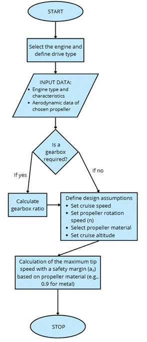
Fig.
1. Diagram of the preliminary process of
selecting the propulsion unit and propulsion system configuration
2.2. Example
engine characteristics
Electric
propulsion systems in aviation constitute one of the most dynamically
developing directions of modern engineering. The use of electric motors allows
for a significant reduction in noise emissions as well as simplification of
propulsion system design. Despite significant limitations related to battery
energy density, the development of energy storage technologies and hybrid
systems indicates a growing potential for the application of electric
propulsion, particularly in light aviation, regional aviation, and unmanned
aerial vehicles. There are already available design solutions for electric
motors optimized for aviation applications, such as the EMRAX 348. This
electric motor exhibits characteristics typical of electric propulsion systems
as shown in Fig. 2, where high torque is available already at low rotational
speeds, and the torque curve as a function of speed is significantly flatter.
The motor power increases with rotational speed until the rated value is
reached, after which it remains at a similar level over a wide range of speeds.
In practice, this enables direct coupling of the motor with the propeller or
the use of a gearbox with a significantly lower reduction ratio compared to an
internal combustion engine.
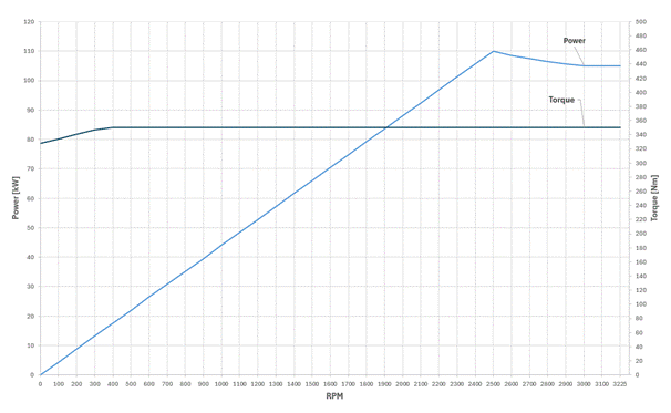
Fig.
2. External characteristics of the EMRAX 348 electric motor [11]
2.3
Aerodynamic analysis of an example propeller
The
aerodynamic analysis was carried out for a three-bladed propeller with a Clark
Y airfoil, adopted as the reference profile shown in
Fig. 3, with well-documented aerodynamic properties. At this stage, the
propeller is treated as an object with a defined geometry, and the purpose of
the analysis is to describe the mechanism of airflow interaction with the blade
and the resulting distribution of aerodynamic forces under different flight
conditions.
The
fundamental element of the aerodynamic description of the blade is its
cross-section, whose geometry is defined by the airfoil
shape and the chord length c. The orientation of the chord relative to
the plane of propeller rotation is determined by the angle θ, understood
as the blade setting angle. The value of this angle, combined with the local
direction of the incoming airflow, defines the angle of attack α.
An
elementary blade section is subjected to the local flow velocity Vs,
which is the resultant of the tangential velocity Vtip,
resulting from the rotational motion of the propeller, and the axial inflow
velocity V∞, associated with the forward motion of the
aircraft. The result of these components determines the local inflow direction
and its angle relative to the airfoil chord c.
This relationship determines both the magnitude of the generated aerodynamic
forces and their spatial distribution.
|
a) |
b) |
|
|
|
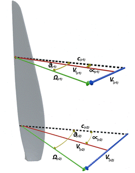
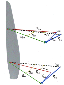
Fig.
3. Analysis of velocity vectors and aerodynamic angles of
a propeller blade in straight flight and during altitude change
In
the case of straight flight, the inflow velocity has a fixed axial direction,
consistent with the direction of motion of the aircraft. The tangential
velocity vector Vtip, resulting
from the angular velocity of the propeller, remains perpendicular to the blade
radius R, and the resultant of both components forms a stable system of
local velocity vectors. For a given angle θ, this leads to a uniquely
defined aerodynamic angle of attack α of the airfoil
at a given blade radius. Under these conditions, the generated aerodynamic
force can be decomposed into an axial component, responsible for generating
thrust T, and a tangential component, generating a resistive torque
opposing the rotational motion of the propeller. The distribution of these
forces along the blade radius is ordered and serves as a reference point for
further analysis.
In
the case of flight with a trajectory different from the direction of the
airflow inflow, for example during climb, both the magnitude and direction of
the axial component of the inflow velocity change. As a result, the local
inflow direction on the blade differs from the straight flight case, which
leads to a change in the resultant flow velocity Vs and
a modification of the local angle of attack α. This change is clearly visible
in the three-dimensional representation of velocity vectors and aerodynamic
forces, where a different
orientation of the resultant velocity and the corresponding
component of the aerodynamic force is observed. Consequently, the proportion of
the axial and tangential force components changes, which affects both the value
of the generated thrust T and the resistive torque acting on the
propeller.
Such
a separation of the analysis into the case of straight flight and flight with a
modified inflow direction allows for an unambiguous interpretation of the
influence of flight conditions on the local angle of attack α and the
distribution of aerodynamic forces on the blade. The visualization of
these relationships provides a clear extension of classical two-dimensional
schemes and forms a coherent introduction to further quantitative analysis of
propeller operation.
2.4 Kinematic
constraints and propeller operating conditions
Based
on the defined input parameters and the adopted aerodynamic model of the
propeller, additional constraints are introduced, resulting directly from the
operating conditions of the propulsion system. One of the key constraints is
the maximum allowable linear speed of the blade tip Vad,
referenced to the local speed of sound. This limitation arises from the need to
avoid wave phenomena, a rapid increase in aerodynamic drag, and unfavorable dynamic loads acting on the blade.
In
order to account for these effects in the algorithm, a safety margin dependent
on the propeller material was adopted. For the analyzed
metal propeller, it was assumed that the maximum blade tip speed does not
exceed 90% of the local speed of sound. The adoption of such a margin allows
for maintaining safe operating conditions of the propeller over the entire
considered range of rotational speeds.
Based
on the velocity Vad and the prescribed rotational
speed of the propeller, the maximum allowable propeller diameter Dmax is determined according to relation
(1). This limitation is kinematic in nature and constitutes an upper geometric
bound, independent of further aerodynamic and performance analyzes.
|
|
|
(1) |

where:
RPS –
propeller rotational speed [1/s],
Vad
– maximum propeller speed defined by safety factor [m/s],
V –
flight speed [m/s].
The
Dmax determined in this way
constitutes one of the fundamental assumptions for further calculations and
defines the range within which propeller geometric variants are analyzed. Only in the next stage is it possible to relate
this limitation to the geometric characteristics of the propeller and to
evaluate its efficiency as a function of flight conditions and the propulsion
unit.
3.
DETERMINATION
OF GEOMETRIC AND AERODYNAMIC PROPELLER PARAMETERS
Based
on the characteristics of the propulsion unit, flight conditions, and the
kinematic limitation of the propeller, it is possible to determine the
preliminary working diameter of the propeller. This stage, presented in the
block diagram shown in Fig. 4, is based solely on the parameters and
assumptions adopted earlier and constitutes their direct computational
consequence.
The
basis for further analysis consists of dimensionless parameters describing
propeller operation, particularly the advance ratio J defined by
equation (2) and the power coefficient Cp defined by relation
(3). The advance ratio J is defined as the forward distance traveled by the aircraft during one revolution of the
propeller and results directly from the assumed flight speed and propeller
rotational speed. The power coefficient Cp expresses the
power requirement of the propeller in relation to its diameter, rotational
speed, and air density, and is calculated based on the power available from the
propulsion unit and the assumed flight conditions. The values of both
parameters are not selected but follow directly from the previously adopted
assumptions.
|
|
|
(2) |

where:
RPS –
propeller rotational speed [1/s],
D – propeller diameter [m],
V – flight speed [m/s].
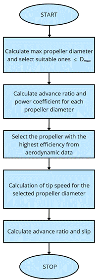
Fig.
4. Diagram of the process of selecting the propeller diameter
and blade setting angle θ
for a selected propulsion unit
|
|
|
(3) |
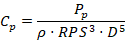
where:
Pp – power
absorbed by the propeller [W],
ρ –
air density [kg/m3],
D – propeller diameter [m],
RPS –
propeller rotational speed [1/s].
3.1. Propeller
geometric parameters – analysis of possible solutions
In
the first step, a set of working diameters Di smaller than
the previously determined limit value Dmax
is considered. For each analyzed diameter Di,
with unchanged assumptions regarding flight speed V, propeller
rotational speed Ω,
and propulsion unit power P, the corresponding values of advance ratio J
and power coefficient Cp are determined. These values are
then plotted on the power coefficient versus advance ratio chart shown in Fig.
5, containing families of curves corresponding to different values of the
geometric blade setting angle θ. On this basis, the blade setting angle is
determined at which the propeller power requirement matches the power available
from the propulsion unit for a given diameter.
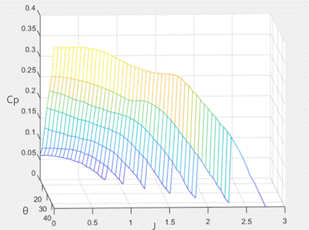
Fig. 5. Power
coefficient characteristics of a three-bladed propeller with a Clark Y airfoil
After
determining the angles θ for
the given diameters Di, an evaluation of the propeller
efficiency ηp is
carried out. For this purpose, the calculated values of the advance ratio J are
correlated with propeller efficiencies, as shown in Fig. 6. Then, the curve
corresponding to the determined angle θ is selected, and on this basis,
the efficiency ηp is
determined for successive propeller diameters Di. The
procedure is repeated for all considered diameters, and the selection of the
working diameter is made based on the obtained efficiency values ηp as
the solution ensuring the highest aerodynamic efficiency under the assumed
conditions.
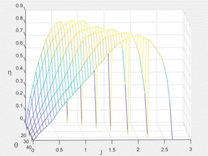
Fig. 6.
Efficiency characteristics of a three-bladed propeller with a Clark Y airfoil
3.2.
Verification of propeller diameter selection
After
determining the propeller diameter, it is possible to verify the obtained
solution with respect to the assumptions adopted in earlier stages of the
algorithm as shown in equation (4). First, the linear speed of the blade tip Vtip is calculated for the diameter Di
and the given propeller rotational speed. The obtained value is compared with
the allowable blade tip speed Vad, resulting from the adopted
safety margin, which allows for an unambiguous assessment of compliance with
kinematic constraints.
|
|
|
(4) |

where:
V – flight speed [m/s],
RPS –
propeller rotational speed [1/s],
D –
propeller diameter [m].
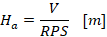
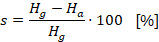
In
parallel, it is possible to determine the propeller slip s, understood
as the difference between the geometric pitch Hg and the
aerodynamic pitch Ha. The geometric pitch Hg
results directly from the propeller geometry and the selected angle θ, while Ha
is determined based on the actual forward velocity of the aircraft and the
propeller rotational speed, as shown in equations (5) and (6). The slip s
represents a measure of losses resulting from aerodynamic interactions and
allows for the assessment of the degree of utilization of the propeller’s
potential under given flight conditions as defined by equation (7).
|
|
|
(5) |

where:
R – propeller radius [m],
θ –
blade setting angle [deg].
|
|
|
(6) |
where:
RPS – propeller rotational speed
[1/s],
V – flight speed [m/s].
|
|
|
(7) |
where:
Ha – aerodynamic
pitch [m],
Hg – geometric
pitch [m].
The
determination of Vtip and the slip s
constitutes the final stage of verifying the correctness of the selected
diameter Di. Meeting the kinematic constraints and obtaining
an acceptable slip value confirm that the selected solution is consistent with
the assumptions of the algorithm and may be adopted as a correct configuration
of the engine-propeller system for further work. After determining the
propeller's diameter and the preliminary operating parameters, it is possible
to proceed to the analysis of the cooperation between the propeller and the
propulsion unit under flight conditions.
Based
on the determination of the actual operating points of the propeller-engine
system and their subsequent evaluation in terms of aerodynamic efficiency and
operational economy, an analytical coupling of the propeller and propulsion
unit characteristics is performed. This enables a transition from geometric
analysis to operational analysis, as shown in the block diagram Fig. 7.
The
next step is to determine the operating points of the engine-propeller system.
The analysis is carried out as a function of the propulsion unit at rotational
speed Ω. A
discrete set of rotational speeds is considered, covering the significant
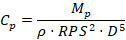
operating range of the engine. For each rotational speed, the power delivered
by engine P is known, resulting directly from its characteristics. On
this basis, for each value of rotational speed, the propeller power coefficient
Cp corresponding to the current operating conditions is
calculated according to equation (8).
|
|
|
(8) |
where:
Mp –
torque on the motor shaft [Nm],
ρ –
air density [kg/m3],
D – propeller diameter [m],
RPS – propeller rotational speed
[1/s].
Then,
using the geometric characteristics of the analyzed
propeller and the previously determined blade setting angle θ, the
corresponding value of the advance ratio J is determined for each value
of Cp. The analysis is carried out based on the
characteristics of the relationship between the power coefficient and the
advance ratio for a constant value of the angle θ, which
ensures consistency of calculations over the entire analyzed
range of rotational speeds.
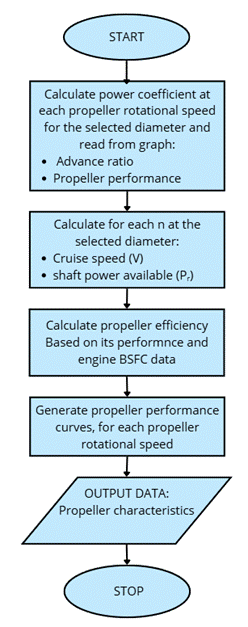
Fig. 7.
Diagram of the procedure for determining the characteristics of
the engine-propeller propulsion system
After
determining J, the propeller efficiency ηp is
determined. For a given value of J and the same angle θ, efficiency
characteristics are used, from which the corresponding value of ηp is
read. As a result, for each operating point, a set of data is obtained
including rotational speed, engine power, power coefficient, advance ratio, and
efficiency.
Based
on the advance ratio, rotational speed, and propeller diameter, the
corresponding flight speed and rated power are calculated equations (9) and
(10). In this way, a table of operating points of the propeller-engine system
is created in Tab. 1, forming the basis for further analysis.
|
|
|
(9) |
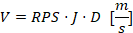
where:
J – advance
ratio,
D – propeller diameter
[m],
RPS – propeller rotational speed
[1/s].
|
|
|
(10) |

where:
Pp – power
absorbed by the propeller [W],
ηp –
propeller efficiency.
Tab. 1
Operating
points of the engine-propeller propulsion system
as a function of propeller rotational speed
|
RPS |
P [W] |
Cp |
J |
η [%] |
V [m/s] |
Pr [kW] |
V [km/h] |
|
54 |
105000 |
0,031 |
0,9 |
83 |
91,37 |
87,15 |
328,9248 |
|
52 |
105000 |
0,035 |
0,88 |
83,5 |
86,03 |
87,675 |
309,70368 |
|
50 |
105000 |
0,039 |
0,86 |
84 |
80,84 |
88,2 |
291,024 |
|
48 |
106000 |
0,045 |
0,8 |
83 |
72,19 |
87,98 |
259,8912 |
|
46 |
107000 |
0,051 |
0,79 |
82,5 |
68,32 |
88,275 |
245,94912 |
|
44 |
109000 |
0,060 |
0,72 |
82 |
59,56 |
89,38 |
214,41024 |
|
42 |
110000 |
0,070 |
0,65 |
78 |
51,32 |
85,8 |
184,7664 |
|
40 |
104760 |
0,077 |
0,58 |
72 |
43,62 |
75,4272 |
157,0176 |
|
38 |
99520 |
0,085 |
0,35 |
55 |
25,00 |
54,736 |
90,0144 |
3.3.
Criteria for selecting the operating point of the engine-propeller system
The
obtained table of operating points makes it possible to take into account the
criterion of operational efficiency of the propulsion unit. Selecting the point
with the highest propeller efficiency alone does not always lead to the most favorable operating conditions; therefore, it is necessary
to relate the results to the energy characteristics of the engine.
In
the case of an internal combustion engine, the analysis would be carried out
based on brake specific fuel consumption (BSFC) maps, allowing identification
of the range of rotational speeds and loads characterized by minimal fuel
consumption. For an electric motor, an analogous criterion is formulated based
on motor efficiency maps, enabling the identification of the range of
rotational speeds at which energy conversion efficiency reaches its maximum
values presented in Fig. 8.
Among
the operating points determined in Tab. 1, those that fall within the range of
rotational speeds favorable from the perspective of
energy consumption are preferred. In the case of a discrepancy between maximum
propeller efficiency and minimum energy consumption, the selection of the
operating point constitutes a compromise, with priority given to the criterion
of the operational economy.
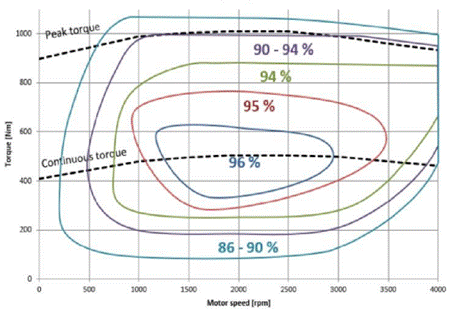
Fig.
8. Efficiency map of the EMRAX 348 electric motor
as a function of rotational speed and torque [11]
4.
DETERMINATION
OF PROPELLER GEOMETRY
Based
on the results of the propeller selection algorithm, a geometric model was
developed, constituting a spatial representation of the obtained parameters.
This model was created based on a known reference geometry, appropriately
scaled to the diameter resulting from the calculations. Its purpose is to
present the resulting propeller geometry and to enable its further analysis in
both geometric and aerodynamic terms.
The
three-dimensional propeller model reflects the distribution of blade geometry
along the radius, resulting directly from the applied algorithm. The use of the
Clark Y aerodynamic profile and the determined distribution of angles of attack
allows validation of the obtained geometry with the adopted aerodynamic
assumptions. The model enables analysis of the continuity of blade setting
changes and the relationship between geometry and the operating conditions of
the propeller-engine system. The developed geometric form represents the
physical outcome of the algorithm and allows assessment of its correctness in
the context of the actual propeller design, as shown in Fig. 9. The model thus
serves as an interpretative tool, linking computational results with their
spatial representation.
For
the analysis of local aerodynamic properties of the blade, working sections
were applied, determined in a manner corresponding to the actual operating
conditions of the propeller in rotational motion. These sections were obtained
by defining the blade geometry on the surface of a cylinder coaxial with the
axis of propeller rotation and then unwrapping the resulting section onto a
plane, as shown in Fig. 10. The aerodynamic section defined in this way
corresponds to Vs and enables analysis of the working airfoil under conditions resulting from rotational motion.
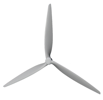
Fig.
9. Geometric model of the designed propeller for
the analyzed engine-propeller propulsion system
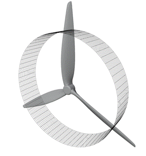
Fig.
10. Example surface of motion of flow particles around the blade at
a given radius R=0.75
Example
sections were created for selected propeller radii: R=0.3, R=0.55,
and R=0.75, which allows for the assessment of changes in airfoil shape along the radius and their relationship with
the distribution of aerodynamic load. These sections represent the local
working airfoils of the blade at the indicated
radius, as shown in Fig. 11.
The
analysis of the sections allows for a qualitative assessment of the influence
of blade setting distribution on the airfoil shape
and its orientation relative to the local flow velocity Vs.
Particular attention was given to the section at radius R=0.75, which in
the propeller selection algorithm serves as the reference point for determining
the blade setting angle θ.
|
a) |
b) |
|
|
|
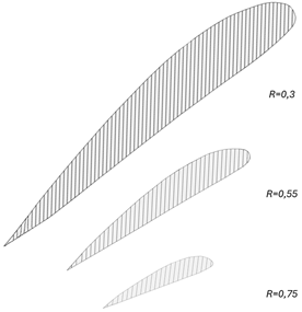
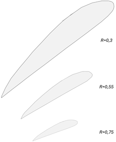
Fig.
11. Comparison of aerodynamic and geometric blade sections at
radius R=0.3, R=0.55, and R=0.75
The
presented sections allow for a direct correlation between the results of the
algorithm and the local aerodynamic properties of the blade and constitute an
important element in the interpretation of the obtained results. However, it
should be emphasized that the chords determined for the aerodynamic airfoil are longer than the corresponding chords of the
geometric airfoil, and the scale of this difference
varies along the blade radius. In the conducted analysis, it was found that for
the section located at the relative radius R=0.3, the chord extension is
approximately 14.0%, for the section at R=0.55 approximately 14.9%, and
for the section at R=0.75 approximately 16.3%. This is the result of the
nonlinear mapping of the section on a rotational surface and its unwrapping
into a flat form, because of which this difference does not have a constant
value along the entire blade length. Taking this effect into account is
significant in the interpretation of section geometry and in further analysis
of the aerodynamic properties of the propeller.
5.
ANALYSIS
OF THE ENGINE-PROPELLER SYSTEM AS A FUNCTION OF PROPELLER ROTATIONAL SPEED
Based
on the selected operating points, it is possible to develop characteristics of
the propeller-engine system as a function of propeller rotational speed RPS.
The propeller rotational speed serves as the independent variable,
enabling a consistent comparison of propulsion system operating parameters. It
is possible to define the relationship between flight speed and rotational
speed RPS, as shown in Fig. 12. The characteristics of available power
Pr presented in Fig. 13 and efficiency
ηp
shown in Fig. 14 are then determined.
These
characteristics allow for the evaluation of the behavior
of the propeller-engine system within the analyzed
operational range and provide a basis for comparing results obtained for
different types of propulsion units.
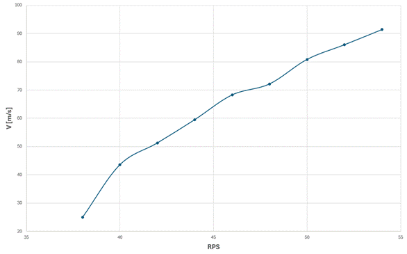
Fig.
12. Variation of aircraft forward speed as a function of propeller rotational
speed
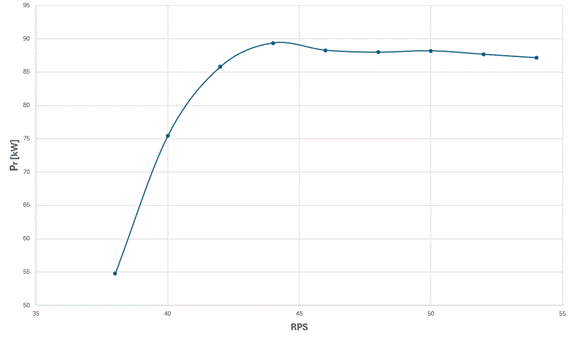
Fig.
13. Variation of available power of the engine-propeller system as a function
of propeller rotational speed
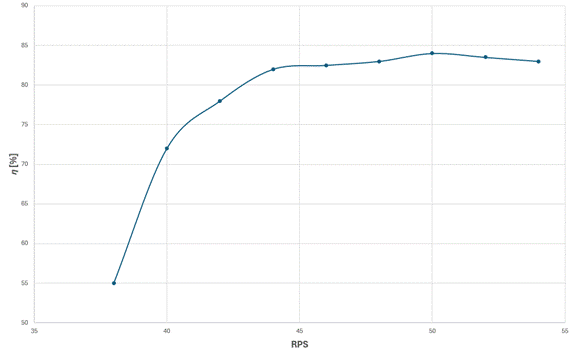
Fig.
14. Efficiency of the engine-propeller system as a function of propeller
rotational speed
Based
on the presented characteristics, relationships can be identified between
propeller rotational speed, flight speed V, available power Pr, and the efficiency of the
engine-propeller system ηp.
With increasing rotational speed, a nearly linear increase in flight speed V
is observed, indicating effective conversion of propulsion power into thrust T
within the analyzed operating range.
At
the same time, the available power characteristic Pr
reaches a maximum in the mid-range of rotational speeds and then stabilizes,
suggesting the achievement of an optimal operating point of the propulsion
system. A similar trend is observed for efficiency ηp,
which increases with rotational speed, reaches a maximum in a similar range,
and then shows a tendency to stabilize or slightly decrease. This indicates
that further increases in rotational speed do not result in a proportional
increase in efficiency but only lead to increased system loads.
From
an operational perspective, this indicates the existence of an optimal
operating range of the propeller, in which the highest efficiency and a favorable ratio of generated thrust T to consumed
power are achieved. Operation outside this range leads to reduced energy
efficiency and increased aerodynamic losses, which is of direct importance in
the selection of propulsion system parameters and its control in different
phases of flight.
6.
SUMMARY
The
conducted analysis of the proposed algorithmic approach to determining
geometric and aerodynamic parameters for propeller selection can be implemented
in a universal manner, regardless of the type of propulsion unit used, provided
that torque and power characteristics are employed as the primary input data.
The applied algorithm enables an unambiguous determination of propeller
operating parameters while maintaining the same geometry, which allows for
direct comparison of different propulsion configurations.
From
the perspective of propeller selection, kinematic constraints are of key
importance, in particular the maximum allowable blade tip speed. This
limitation directly determines the maximum propeller diameter and constitutes a
primary design condition, independent of engine characteristics.
The
study has shown that the selection of propeller diameter and blade setting
angle is a compromise problem, in which the maximization of aerodynamic
efficiency ηp
must be considered together with the available power Pr
and the operating conditions of the propulsion system. The highest
propeller efficiency does not always correspond to the optimal operating point
of the entire engine-propeller system.
The
proposed procedure allows for the determination of propulsion system operating
points and their analysis as a function of rotational speed, which constitutes
an important tool in the design and selection of propulsion systems in light
and unmanned aviation. Propeller selection should be treated as a problem of
matching characteristics rather than designing geometry, while the presented
procedure is theoretical in nature and is based on simplified models that,
under real operating conditions, may lead to different results due to the
influence of higher-order aerodynamic phenomena, interactions with the
airframe, and flow unsteadiness.
Nomenclature
c –
chord length [m],
Cp –
power coefficient [–].
D –
propeller diameter [m],
Ha –
aerodynamic pitch [–],
Hg –
geometric pitch [m],
J –
advance ratio [–],
Mp – torque on
the motor shaft [Nm],
P –
engine power [kW],
Pp –
power absorbed by the propeller [W],
Pr –
available power [W],
R –
propeller radius [m],
RPS –
propeller rotational speed [1/s],
s –
propeller slip [%],
T –
thrust force [N],
V –
flight speed [m/s],
Vad –
maximum propeller speed defined by safety factor [m/s],
V∞ –
free-stream airflow velocity vector [m/s],
Vs –
slipstream velocity vector [m/s],
Vt –
resultant airflow velocity vector [m/s],
Vtip – blade tip
speed [m/s],
α – blade angle
of attack [deg],
ηp –
propeller efficiency [–],
θ – blade
setting angle [deg],
ρ – air density
[kg/m³],
Ω – propeller
angular velocity vector [rad/s].
References
1.
Buermann D., E.
Hartman. 1939. The aerodynamic characteristics of six full-scale propellers
having different airfoil sections.
2.
Bukowski J., W. Łucjanek. 1986. Propeller Drive: Theory and Design.
Warsaw: Publishing House of the Ministry of National Defense.
3.
Alshahrani A. 2020.
„Analysis and initial optimization of the propeller design for small,
hybrid-electric propeller aircraft”. Master’s thesis, Stockholm.
4.
MacNeill R., D.
Verstraete. 2006. Propeller optimisation for an
electrically-powered tactical UAS. The University of Sydney.
5.
Reyner C., C. Lee, D.
Kim, R. P. Liem. Mission-based optimal propeller selection for VTOL SUAV
configuration. The Hong Kong University of Science and Technology; École
Nationale de l’Aviation Civile.
6.
Slavik S., J. Klesa. Propeller selection by means of Pareto optimal
sets applied to flight performance. Czech Technical University.
7.
Gur O., J. Feldman.
„Engine-propeller matching”. Israel Aerospace Industries.
8.
EMRAX d.o.o. EMRAX
348 Technical Datasheet. Available at: https://emrax.com/e-motors/emrax-348/.
9.
Răducanu G., R.-M. Dincă, et
al. 2017. „Airplane propellers aerodynamic design and performances analysis”. Review
of the Air Force Academy 15(1): Article 12.
10. Adebimpe S. O. 2023. „Propeller aerodynamic design
and optimization”. Preprints.org. DOI:
https://doi.org/10.20944/preprints202310.0418.v1.
11. Oliveira N. L., A.C. de C. Lemonge,
P.H. Hallak, K. Kyprianidis, S. Vouros,
M.A. Rendón. 2025. „Propeller design optimization and an evaluation of
variable rotational speed flight operation under structural vibration
constraints”. Machines 13(6): 490. DOI:
https://doi.org/10.3390/machines13060490.
12. Zheng F., W. Wang, S. Li, J. Zhang. 2015. „Matching
characteristics of propeller and engine of fuel-powered quadrotor aircraft”. Proceedings
of the 2015 2nd International Conference on Machinery, Materials Engineering,
Chemical Engineering and Biotechnology. DOI:
https://doi.org/10.2991/mmeceb-15.2016.70.
13. McDonald R. A. 2015. „Modeling of electric motor
driven propellers for conceptual aircraft design”. AIAA SciTech Forum.
DOI: https://doi.org/10.2514/6.2015-1676.
14. Filippone A. 2006. „Aerodynamics of propellers”. Progress
in Aerospace Sciences 42(5-6): 333-364. DOI:
https://doi.org/10.1016/j.paerosci.2006.10.001.
15. Zenowicz P., W. Skarka. 2021. „Analysis and optimization of
the propeller shape for a stratospheric drone research platform”. Advances
in Transdisciplinary Engineering 16: 147-156. DOI:
https://doi.org/10.3233/ATDE210126.
16. Kim H., S. Park, J. Lee. 2023. „Development
of an acoustic fault diagnosis system for UAV propeller blades”. CEAS
Aeronautical Journal 15: 881-893.
17. Hoffmann W., M. Żokowski. 2020. „Optimization of
propeller aeroacoustics using genetic algorithms”. Science for Defence and Environment 4(2): 45-58.
18. Zhang J., W. Li, L. Ren. 2024. „On minimum power
flight formations of lifting propellers”. Aerospace Science and Technology
149: 109150.
19. Chen Y., P. Li, X. Hu. 2024. „Helicopter rotor in a
propeller slipstream”. Aerospace Science and Technology 150: 109341.
20. Wei H., Z. Zhang, F. Zhou. 2024. „Wing-propeller
aerodynamic interaction”. Aerospace Science and Technology 151.
21. Wang L., X. Liu, Q. Zhang. 2024. „Optimization
framework for high-altitude propellers”. Aerospace Science and Technology
153. DOI: https://doi.org/10.3390/aerospace11110906.
22. Zanotti A., A. Velo, C. Pepe, A. Savino, D. Grassi,
L. Riccobene. 2024. „Aerodynamic interaction between tandem propellers in eVTOL
transition flight configurations”. Aerospace Science and Technology 147:
109017. DOI: https://doi.org/10.1016/j.ast.2024.109017.
23. Biczyski M., R. Sehab, J. F. Whidborne, G. Krebs,
P. Luk. 2020. „Multirotor sizing
methodology with flight time estimation”. Journal of Advanced Transportation
2020: Article 9689604. DOI: https://doi.org/10.1155/2020/9689604.
24. Podsędkowski M., D. Obidowski, M. Lipian. 2025.
„Enhancing drone propellers: Practical insights from BEM-based pitch
optimization”. Aerospace Science and Technology 163: 110332. DOI:
https://doi.org/10.1016/j.ast.2025.110332.
25. Gao M., W. Guo, J. Sun, Y. Huang, Y. Cai. 2026.
„Aerodynamic optimization design of propellers for multi-rotor unmanned aerial
vehicles based on NSGA-II”. In: Advances in Construction Machinery and
Vehicle Engineering. Springer. DOI:
https://doi.org/10.1007/978-981-96-5527-4_65.
Received 23.03.2026; accepted in
revised form 02.06.2026

Scientific
Journal of Silesian University of Technology. Series Transport is licensed
under a Creative Commons Attribution 4.0 International License