Article citation information:
Topal, T., Candaş, A.,
Kalay, E., İmrak, C.E. Thermomechanical
behavior of IN718 bolted joints in aerospace propulsion at elevated
temperatures. Scientific Journal of
Silesian University of Technology. Series Transport. 2026, 131, 207-228. ISSN: 0209-3324. DOI: https://doi.org/10.20858/sjsutst.2026.131.13
Tahsin TOPAL[1],
Adem CANDAŞ[2],
Eren KALAY[3],
Cevat Erdem İMRAK[4]
THERMOMECHANICAL BEHAVIOR OF IN718 BOLTED JOINTS IN AEROSPACE PROPULSION
AT ELEVATED TEMPERATURES
Summary. In recent years, the need for advanced fasteners has
increased significantly in state-of-the-art engineering topics such as the
aerospace and defense industries. The components and
assemblies used in these sectors must operate under extremely severe conditions
with the required performance and reliability. Literature reviews examine the behavior of bolted joints at room and moderate
temperatures; however, comprehensive analyses and calculations conducted across
a wide range of temperatures, from low to high, are limited. This study focuses
on the thermomechanical behavior of superalloy bolted
joints used in the assembly of structural parts of gas turbine engines.
Analytical and numerical evaluations of flanged bolted joints operating at room
temperature 24°C and 700°C were conducted. This study also completed the
determination of bolt preload, axial stiffness, and stress distribution on the
joint under thermal and mechanical loading. Furthermore, the aim was to compare
the results obtained from Finite Element Analysis (FEA) and exact solution. The
results indicate that a decrease in bolt preload and joint stiffness occurs due
to thermal expansion mismatch and temperature-dependent compliance effects
resulting from elevated temperature. Additionally, significant changes were
observed in the tensile stresses of 12-point M10x1.25 aerospace-standard bolts
at 700°C operating condition, indicating the onset of critical conditions for
joint integrity. Analyses also confirm that maintaining adequate preload and
stiffness during operation is essential to maintain joint integrity and prevent
loss of structural stability. This study provides a comprehensive assessment of
the high-temperature mechanical behavior of
superalloy bolted connections. The findings contribute to the design and
optimization of bolted joints used in aerospace propulsion systems by providing
practical insights into ensuring safety, durability, and performance under
extreme thermal conditions.
Keywords: bolted joint,
superalloys, elevated temperature, aerospace fasteners, thermomechanical
analysis
1. INTRODUCTION
Mechanical
couplings employed in defense and aerospace
applications are usually subjected to a challenging combination of thermal,
mechanical, and constraint-driven loads. Temperature fields across casings and
structural rings are rarely uniform, and gradients can persist over both steady
and transient operation. In gas turbine engines, these effects are further
amplified by internal pressure levels and assembly constraints, which limit
free thermal expansion and transform thermal strains into secondary stresses at
interfaces. These coupled mechanisms shape not only the stress state of
individual components but also the behavior of joints
that connect modules and transfer loads between structural subassemblies. This
means joints are often exposed to “hidden” loads that do not appear as external
forces but emerge from compatibility requirements and thermal restraint
In
bolted joints operating under elevated thermal conditions, one of the primary
sources of uncertainty is introduced during assembly. Torque-controlled
tightening is widely used in important applications due to its simplicity and
process-level repeatability. However, the resulting mechanical state is highly
sensitive to frictional conditions at the threads and under the bearing
surfaces. Surface finish, lubrication, coatings, and installation practice can
change the achieved clamp force significantly even when torque is controlled
and nominally identical. As a result, torque-preload relationship is generally
treated as an engineering estimate that should include scatter bounds, rather
than a deterministic calculation
Nickel-based
superalloys such as IN718 are widely used in high-temperature aerospace
applications due to their favorable combination of
strength, corrosion resistance, and machinability. Nevertheless, both Young’s
modulus and yield strength decrease as temperature approaches 700°C, and the
associated stiffness reduction directly affects joint spring balance and
preload retention. This means that a joint structurally adequate at room
temperature may undergo a meaningful change in clamp force and interface behavior at elevated temperature. Preload retention
therefore requires explicit verification. In this context, stiffness
degradation can be as consequential as strength degradation
A
substantial body of work exists on the modeling and
analysis of bolted joints, addressing issues such as contact behavior
2. MATERIALS AND METHODS
The flange geometry, bolt
arrangement, and temperature-dependent material properties used in the analyses
are first introduced. The definition of the torque-preload relationship and the
preload bounds adopted to represent assembly variability are then described.
This is followed by the analytical stiffness-based joint model and the
definition of the joint stiffness factor used to evaluate preload retention. Finally,
the finite element model scope, geometric representation, contact definition,
boundary conditions, and solver settings employed in the numerical analyses are
outlined.
2.1. Geometry and material data
The investigated configuration
consists of a two-flange bolted joint incorporating a rabbet feature and
aerospace-style fine-thread fasteners, specifically M10 bolts with a 1.25 mm
pitch (M10×1.25) and 12-point heads. One in six sectors of the body is employed
to represent the full circumferential assembly efficiently while preserving
circumferential behavior through periodic boundary
conditions as shown in Fig. 1. All joint components, including the bolt, nut,
and flange members, are modelled using the nickel-based superalloy IN718.
Temperature-dependent Young’s modulus and 0.2% yield strength are employed at
both 24°C as room-temperature and 700°C as elevated-temperature conditions.
Using sector modeling improves efficiency while
keeping the mechanical coupling that drives flange rotation and contact
redistribution. The analysis focuses on a representative two-flange bolted
joint geometry, with the geometric details provided in Fig. 1.
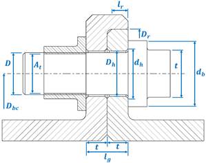
Fig. 1. The geometrical details of a two-flange
bolted joint
The geometric and material
parameters used for the numerical analysis are defined in Tab. 1.
Tab. 1
Key Geometric and Material Parameters
|
Parameter |
Symbol |
Value |
Unit |
|
Bolt Nominal Diameter |
|
10 |
mm |
|
Bolt Tensile Area |
|
61.2 |
mm² |
|
Grip Length |
|
10 |
mm |
|
Single Flange Thickness |
|
5 |
mm |
|
Bolt Head Diameter |
|
15.7 |
mm |
|
Applied Torque |
|
65 |
Nm |
|
Rabbet Engagement Length |
|
3.85 |
mm |
|
Rabbet Diameter |
|
351 |
mm |
|
Flange Hole Diameter |
|
10.8 |
mm |
|
Flange Hole Diameter with Chamfer |
|
11.8 |
mm |
|
Bolt Circle Diameter |
|
165 |
mm |
|
Nut Factor |
|
0.20 |
- |
|
Young’s modulus
(24 °C) |
|
200,000 |
N/mm² |
|
Young’s modulus
(700°C) |
|
158,900 |
N/mm² |
|
Coeff. of Thermal Exp. @ 700°C |
|
|
1/°C |
|
0.2% Yield Strength (24°C) |
|
1034 |
MPa |
|
0.2% Yield Strength (700°C) |
|
938 |
MPa |


2.2. Torque-Preload Definition
The nominal assembly preload is
defined using the widely adopted torque-tension relation,
 (1)
(1)
where T is the applied tightening
torque, d is the nominal bolt diameter, and K is the nut factor
(torque coefficient) representing the combined influence of thread and bearing
friction. In torque-controlled tightening, K is not a fixed material
constant but varies with lubrication condition, surface finish and treatment,
and installation practice. Consequently, engineering design typically adopts a
nominal K value and accounts for the associated uncertainty through
preload scatter rather than treating K as a deterministic parameter. The
nut factor was taken as 0.20 which is commonly assumed for design-level
estimates, while emphasizing the strong sensitivity of achieved preload to
friction variability
The tightening torque was set to T =
65 Nm based on practical installation targets for comparable bolt sizes and
typical nut-factor ranges
These bounds were intentionally
carried into the margin evaluation. The conservative preload case depends on
the governing failure mode. Maximum preload is more demanding for
strength-driven checks, such as bolt axial stress and local bearing pressure, which
can increase with clamp force. Conversely, minimum preload is more demanding
for clamp-dependent checks, including transverse slip resistance and interface
separation, as both are directly governed by the retained clamp force
2.3. Analytical stiffness model and joint
stiffness factor
The joint is idealized as a bolt
spring in tension and a member spring in compression. Bolt stiffness kb
and member stiffness km are calculated using temperature-dependent Young’s
modulus for 24°C and 700°C. The joint stiffness factor is:
 (2)
(2)
This factor governs the sensitivity
of bolt load to separating demand. A lower joint stiffness factor indicates
member-dominated stiffness. A higher one indicates bolt-dominated sensitivity.
For this joint, the computed value is C = 0.251. The computed joint stiffness
factor is used later to support interpretation of the margin hierarchy,
particularly where bolt bending sensitivity and flange net-section bending
become important. A low joint stiffness factor value is desirable for fatigue
resistance, as it minimizes the alternating stress seen by the bolt. A joint
stiffness factor below 0.5 is generally recommended
2.4. Model scope, representation, and solver
settings
To capture nonlinear contact behavior and coupled thermo-mechanical effects, a
three-dimensional finite element model is developed under ANSYS Workbench
Mechanical (version 19.2). A one-in-six sector representation is employed to
reduce computational cost while preserving the full circumferential response
through periodic boundary conditions. Thread geometry is not represented
explicitly as a helical form. Instead, thread engagement is modeled
in a simplified manner to ensure stable application of bolt pretension and
robust meshing in the bearing and interface regions. This simplification is
appropriate for evaluating preload retention, contact evolution, and
component-level stress redistribution within the joint. The model is not
intended to resolve local thread-root notch stresses, which would require
explicit thread representation or a dedicated sub-modeling
approach
The finite element mesh is
constructed to adequately resolve bearing interfaces beneath the bolt head and
nut, flange-to-flange contact edges, and geometric transitions where elevated
stress gradients are expected. A global element size is used to keep the model
uniform. Local refinements are applied near contact edges and fillets to
control peak stress sensitivity. All components are meshed using linear
SOLID185 elements with a sweep meshing strategy. A global element size of 1.4
mm is adopted, complemented by edge sizing controls to promote smooth mesh
transitions along flange radii and bolt-nut geometric changes. To enable the
sweep method, each component is prepared with a sweepable
topology by subdividing the solid bodies into volumes with clearly defined
source and target faces. This partitioning allows the mesh to be propagated
through the thickness in a controlled and consistent manner. To
objectively evaluate spatial convergence, the local element size at the
critical thread region was systematically reduced from a coarse baseline of
4.00 mm down to a highly refined 1.20 mm. The corresponding equivalent von
Mises stress values recorded at the reference node are summarized in Tab. 2.
Tab. 2
Mesh Convergence Study Results at the
Critical Thread Root
|
Mesh Size (mm) |
Equivalent von Mises Stress (MPa) |
Relative Change (%) |
|
4.00 |
161.00 |
- |
|
3.50 |
176.00 |
9.3% |
|
3.00 |
260.00 |
47.7% |
|
2.50 |
267.00 |
2.7% |
|
2.00 |
499.00 |
86.9% |
|
1.40 |
630.00 |
26.3% |
|
1.20 |
625.00 |
-0.8% |
The geometry of the bolt, nut, and
flanges is simplified where appropriate to facilitate high-quality hexahedral
meshing, which is critical for accurate representation of contact behavior and stress distribution. The resulting
sweep-compatible, chunked geometry enables consistent meshing not only of the
flanges but also of the bolt and nut bodies, thereby reducing reliance on
automatic tetrahedral meshing, which can be less predictable in
contact-dominated regions. The final model comprises 85,657 nodes and 67,582
elements. The simplified and partitioned geometry used to achieve the sweep
mesh is illustrated in Fig. 2.
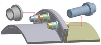
Fig. 2. Chunked and simplified
bodies of one in six sectors
Local mesh refinement was applied in a targeted manner. Bearing surfaces beneath the bolt head and nut, as well as the flange-to-flange contact edge, were refined because these regions govern contact pressure gradients and local stress redistribution. In addition, edge sizing was employed to control element distribution and to obtain smoother mesh transitions at the flange radii and at geometric changes on the bolt and nut, where abrupt size variations can increase skewness or lead to distorted elements. These mesh controls were selected to support stable contact convergence and to improve the reliability of peak stress extraction in regions where stress gradients are expected to be high. Element quality was evaluated using standard ANSYS mesh metrics. The resulting aspect ratio ranged from a minimum of 1.079 to a maximum of 39.605, with an average value of 1.6932. Skewness values showed an average of 0.13834 and a maximum of 0.94277. The Jacobian ratio varied between 1 and 5.2305, with an average of 1.3046. Element quality values ranged from 9.38×10⁻² to 0.99566, with an average of 0.88918, while the orthogonal quality exhibited an average of 0.9631 and a minimum of 5.7227×10⁻². Mesh quality was assessed using these metrics because frictional contact and bolt pretension introduce localized nonlinearities that can amplify the numerical influence of poorly shaped elements. The reported average values indicate a generally well-shaped mesh suitable for nonlinear contact analysis, while the localized worst-case values justify the explicit reporting of quality metrics for transparency and repeatability, particularly in contact-sensitive stress evaluations. The final meshed model is depicted in Fig. 3.
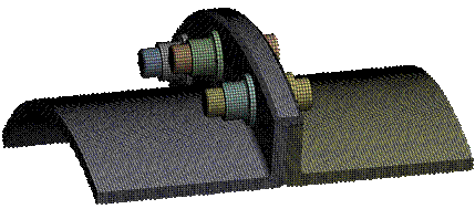
Fig. 3. 3D Geometric model and mesh
details of one in six sectors
To simulate the real-world behavior of the joint, frictional contact is defined at the
flange-to-flange interfaces and at the interfaces between the bolt head/nut
bearing faces and the flange surfaces. The flange-to-flange contact allows
relative sliding between the mating flanges, providing shear resistance, and
more importantly, permits local separation when the external separating
tendency exceeds the available clamping force. This capability is essential for
evaluating interface integrity and clamp-dependent margin checks. Contact between
the bolt head and nut bearing surfaces and the flange faces captures local
micro-slip tendencies and seating or embedding effects under the bearing
surfaces, which can influence contact pressure distribution and stiffness
redistribution following tightening.
A coefficient of friction of μ = 0.15 is assigned to the
frictional contact interfaces. This value was selected as a conservative
lower-friction baseline for the transverse load capacity assessment and is
consistent with engineering references for bolted joints. NASA-STD-5020
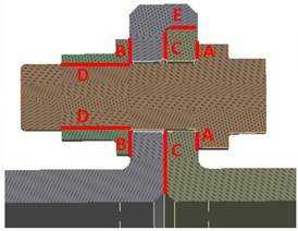
Fig. 4. Visualization of the contact
regions identified by red letter labels
A bonded contact formulation is used
for the simplified interface between the bolt and nut threads. This assumption
represents the threaded engagement as a rigid load transfer path between the
bolt shank and the nut, without explicitly resolving the helical thread
geometry. The intent is to provide a stable and computationally efficient
representation of joint-level behavior, including
preload retention, contact redistribution, and member stresses, rather than to
predict local thread-root notch stresses or stripping behavior.
This modeling approach is consistent with joint-level
finite element studies focused on the global response of bolted connections, as
also adopted in Ref.
The analysis is formulated as a multi-step nonlinear quasi-static simulation to represent the sequential nature of joint assembly and operating load application. Loads are introduced progressively rather than applied simultaneously, and they are not removed between steps; instead, each step builds on the converged state of the previous one. This chronological approach is essential for capturing the path-dependent nature of frictional contact, including stick-slip and local opening transitions, as well as the associated stiffness redistribution. Large-deformation effects are enabled to retain geometric nonlinearity in the presence of contact and to avoid suppressing flange rotation and contact-driven deformation modes. To represent the full joint behavior efficiently, a one in six sector model is employed with cyclic symmetry applied at the sector faces to reproduce the response of the entire assembly. This approach ensures circumferential consistency while preserving the local contact and stress mechanisms of interest. Accurately reproducing the progression from assembly to operation requires a multi-step loading strategy, as it enables tracking of contact state evolution, friction activation, and the coupled thermo-mechanical response once the joint is already clamped. Applied loads and boundary conditions are shown in Fig. 5.
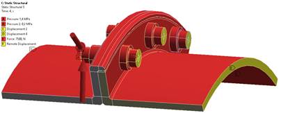
Fig. 5. Applied loads and boundary
conditions at one in six sectors
The first load step establishes the
assembled reference configuration through an initial contact equilibrium and
interference-fit resolution (Applied time = 1 to 4). During this stage, the
solver resolves any initial penetrations or geometric incompatibilities between
contacting surfaces and converges to a stable contact state. No external
service loads are applied in this step. This procedure provides a
mathematically consistent baseline for the subsequent analysis and reduces
sensitivity to contact initialization artifacts, while approximating the
physical seating and alignment of components prior to bolt tightening. Once a
stable contact state is achieved, bolt tightening is introduced through a
dedicated preload step (Applied time = 2 to 4). The axial preload, 32 kN, is applied to the bolt shank using the ANSYS Bolt
Pretension capability. During this step, a geometric offset is imposed at the
bolt-flange bearing contact interfaces to represent seating behavior
and to obtain a stable pretension equilibrium without introducing non-physical
penetration. The resulting pretension level is verified directly from the
solution output to confirm that the target clamp force is achieved before
additional loads are applied. After reaching the specified value, the
pretension is locked and retained for all remaining steps to represent the
assembled condition during operation. Mechanical service loading is then
applied in the form of internal pressure (Applied time = 3 to 4). Pressure
loads representing the gas-path environment are applied to the defined inner
surfaces of the joint, generating tensile ring stresses and introducing a
separating tendency that can locally unload the flange interface. Applying
pressure prior to thermal loading isolates the mechanical response of the
clamped joint under purely mechanical conditions and provides a clear reference
for interpreting the additional load redistribution introduced by temperature.
The final step introduces the thermal environment and completes the operating
load superposition (Applied time = 4). A thermal analysis is first performed by
mapping prescribed boundary temperatures onto selected surfaces to establish
the required operating thermal gradient. The resulting steady-state temperature
field is then transferred to the structural model using the Imported
Temperatures approach. In the same step, the interface resultant force,
extracted from the reaction forces at the corresponding cut boundary, is
applied to the defined cut-section surface to represent reaction transfer
across the sector boundary in the full assembly. With bolt pretension locked
and pressure loading active, the nonlinear contact equilibrium is solved at the
operating temperature level, up to approximately 700°C. This step captures
thermo-mechanical stresses arising from constrained thermal expansion and
reveals the evolution of contact pressure distribution and retained clamp force
under combined operating conditions. The final converged state represents the
joint’s global equilibrium response under the superposition of preload,
pressure loading, imported temperature field, and the applied cut-section
interface force, including contact nonlinearity and preload-retention effects.
3. RESULTS
This section is structured around
four result groups: temperature field, preload loss, stress field, and margin
results. Each group is reported with interpretation rather than only listing
values. The intent is to make the results actionable for design decisions, not
just descriptive.
3.1. Thermal Analysis and Preload Loss
The steady-state thermal solution
reaches approximately 700°C with a non-zero gradient. The temperature
distribution of the joint is shown in Fig. 6. Even when the gradient is modest,
it affects clamp because a preloaded joint is stiff and constraint-driven.
Compatibility transforms thermal strains into internal force changes and
contact redistribution. The mapped field is therefore treated as a primary
input rather than a background condition. This is one of the key reasons why
“uniform temperature” assumptions can underpredict clamp change in real flange
joints.
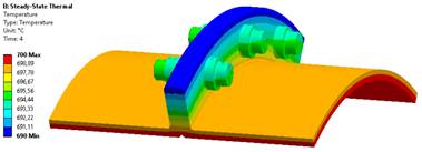
Fig. 6. Temperature contours at
operating condition on one in six sectors
A practical implication is that
preload loss is not driven only by a single bulk temperature value. The spatial
field and the constraint path matter. This is a key reason to map the thermal
solution into the structural model instead of assigning a uniform temperature
when clamp prediction is an objective. This thermal difference, combined with
the reduction in material stiffness at high temperatures, causes a significant
loss of preload. The FEA model captured the preload history, which was compared
to the analytical calculation.
3.2. Analytical and FEA preload comparisons
Preload loss is quantified using an
analytical stiffness-based calculation and an FE extraction using the bolt
pretension feature. Both are treated as thermo-elastic responses in the
operating conditions. The resulting preload loss is not treated merely as a
numerical outcome, but as a practical design consideration when interpreting
clamp-dependent margins, since retained clamp force directly governs interface
integrity and load transfer mechanisms
 (3)
(3)
For the FE approach, pretension is
applied at 24°C to reach the same nominal preload and then locked. Pressure
loads are applied, and the thermal field is mapped to the structural model.
Operating preload is extracted directly from the pretension result (or
equivalent bolt reaction measure) after the thermal step. This extraction
naturally includes the influence of contact redistribution because it is
obtained from the converged nonlinear contact solution. The close agreement
between analytical and FE results is valuable here because it indicates that
the dominant preload-loss mechanism is captured by global
stiffness/compatibility, while local contact effects act as a second-order
modifier for this metric. The FEA model captured the preload history, which was
compared to the analytical calculation as follows:
 (4)
(4)
Consistent with the time-independent
FEA, relaxation loss  and embedding effects
  are assumed to be zero. The preload retention
values at 700°C calculated from the exact solution and finite element analysis
are summarized in Tab. 3.
are assumed to be zero. The preload retention
values at 700°C calculated from the exact solution and finite element analysis
are summarized in Tab. 3.
Tab. 3
Preload retention at 700°C
|
Method |
Preload (24°C) |
Preload (700°C) |
Difference |
|
Exact solution |
32500 |
25873 |
6626 (20.38%) |
|
FEA |
32500 |
26438 |
6062 (18.65%) |
Both methods confirm a significant
preload loss of 18-20% due to thermal effects alone. Both approaches predict a
significant preload reduction at 700°C. The magnitude is not marginal. It
reduces clamp by nearly one-fifth in the evaluated operating state. This
matters because frictional slip resistance, interface pressure distribution,
and separation resistance are all tied to retained clamp force. The agreement
between analytical and FE predictions is also meaningful; however, it should be
interpreted as a consistency assessment rather than as independent validation.
The difference in predicted drop is about 2.1%, indicating that the dominant
thermo-elastic preload-loss mechanism is captured consistently by both
approaches. This supports the stiffness-based method as a reliable early-stage
estimator for thermo-elastic clamp change, while the FE model provides the
local contact and bending resolution needed for stress and margin
interpretation.
3.3. Stress evaluation
The structural response of the joint
was evaluated at two critical states: the assembly condition at room
temperature with preload only, and the operating condition at 700°C under the
combined action of preload, internal pressure, and the applied boundary force.
The equivalent von Mises stress distribution in the bolt and nut under the
assembly condition is shown in Fig. 7.
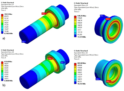
Fig. 7. Equivalent von Mises stress
(MPa) of the bolt and nut
a) time = 2 s and b) time = 4 s
Equivalent von Mises stress (MPa)
contour plot of the Flange1 and Flange2 at the assembly condition is shown in
Fig. 8.
These stress results are summarized in Tab. 4.
Tab. 4
Equivalent von Mises stress (MPa)
|
Component |
Assembly Stress (24°C) |
Operating Stress (700°C) |
Assembly / Operating 0.2% Yield limits |
|
Bolt |
709.5 |
630.5 |
1034 / 938 |
|
Nut |
646.6 |
682.7 |
1034 / 938 |
|
Flange 1 |
371.0 |
479.4 |
1034 / 938 |
|
Flange 2 |
351.6 |
355.6 |
1034 / 938 |
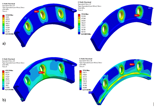
Fig. 8. Equivalent von Mises stress (MPa) of
the flanges a) time = 2 s and b) time = 4 s
The stress trends support the
preload-loss result. The mean bolt stress decreases in the operating state as
the retained clamp force is reduced, which is an expected outcome. In contrast,
local stresses in the nut and in Flange1 increase, indicating load
redistribution within the joint. Contact and stiffness-path changes are driving
the response. High temperature does not simply increase stresses uniformly; it
changes where stresses concentrate. A notable interpretation is that lower bolt
axial stress at temperature does not automatically mean a safer bolt, because
the joint may simultaneously become more sensitive to bending and
interface-driven effects. All reported von Mises stress values remain below the
0.2% yield strength at the corresponding temperature for the evaluated load
case, indicating immediate static feasibility. However, these results represent
a snapshot of the thermo-elastic operating state only. Additional preload loss
mechanisms may develop with time, and localized slip or fretting can become
relevant even when global stress levels remain below yield. For this reason,
the margin discussion emphasizes clamp-dependent criteria alongside
conventional yield-based checks.
3.4. Margin Results
The margin framework is used here as
an organizing tool to condense a wide range of stress results and interface
responses into a consistent set of pass/fail distance metrics. This consistency
is important because different limit states can govern under different preload
conditions. The framework also facilitates transparent interpretation,
particularly in explaining why a large separation margin may coexist with a
comparatively tight flange bending margin. Margins are reported using the
following definition:
 (5)
(5)
Where  is the allowable stress associated
with the relevant limit state, and
is the allowable stress associated
with the relevant limit state, and  is the corresponding applied stress.
The evaluation uses maximum and minimum preload bounds because the most
demanding condition depends on the failure mode. Maximum preload is
conservative for strength-driven checks, since higher clamp increases bolt axial
stress and local bearing/contact pressure. Minimum preload is conservative for
clamp-dependent checks, since lower clamp reduces frictional capacity and
brings the interface closer to opening. This is particularly relevant at
elevated temperature, where the joint has already spent part of its clamp
reserve through thermo-elastic effects
is the corresponding applied stress.
The evaluation uses maximum and minimum preload bounds because the most
demanding condition depends on the failure mode. Maximum preload is
conservative for strength-driven checks, since higher clamp increases bolt axial
stress and local bearing/contact pressure. Minimum preload is conservative for
clamp-dependent checks, since lower clamp reduces frictional capacity and
brings the interface closer to opening. This is particularly relevant at
elevated temperature, where the joint has already spent part of its clamp
reserve through thermo-elastic effects
The bearing/crush margin evaluates
local compressive demand at the under-head and under-nut bearing interfaces
using the local contact pressure/stress demand extracted from the FE solution.
The rabbet net-section bending margin is included as a confirmation check for
the rabbet feature under the operating load case. The TLC margin evaluates
transverse slip resistance at the flange interface and is treated as a
clamp-driven limit state because the available frictional capacity scales with
retained clamp. The separation margin evaluates interface opening resistance
using the retained compressive contact state. These checks allow
strength-driven and clamp-dependent limit states to be compared within the same
margin framework. All structural integrity margin calculations were
consolidated in Tab. 5.
Tab. 5
Consolidated structural integrity
margins
|
Criterion (Margin) |
Assessed limit state |
Condition / Preload Case |
Margin (%) |
|
Bolt tensile stress margin |
Gross axial yielding of bolt
shank |
Assembly / Max Preload |
61.64 |
|
Bolt tensile stress margin |
Gross axial yielding of bolt
shank |
Operating / Nom Preload |
117.36 |
|
Bolt max fiber stress margin |
Combined tension + bending
in bolt |
Operating / Nom Preload |
39.83 |
|
Flange net-section bending
margin (Flange 1) |
Flange yielding in bending
at critical section |
Operating / Nom Preload |
19.15 |
|
Flange net-section bending
margin (Flange 2) |
Flange yielding in bending
at critical section |
Operating / Nom Preload |
54.78 |
|
Bearing / crush margin |
Local compressive yielding
at bearing/contact |
Assembly / Max Preload |
122.48 |
|
Bearing / crush margin |
Local compressive yielding
at bearing/contact |
Operating / Nom Preload |
199.17 |
|
Rabbet net-section bending
margin |
Rabbet section yielding in
bending |
Operating / Nom Preload |
2889.87 |
|
TLC margin |
Slip resistance (friction
vs. transverse demand) |
Operating / Min Preload |
101.67 |
|
Separation margin |
Interface opening resistance |
Operating / Min Preload |
1359.56 |
The tightest strength-based margin
is Flange 1 net-section bending (19.15%), indicating that flange bending is the
primary sizing indicator under the evaluated operating state. The bolt fiber stress margin (39.83%) is noticeably lower than the
bolt tensile margin, which confirms that bending effects remain relevant even
when the bolt axial load decreases due to preload loss. Rabbet bending and
separation margins are non-governing for the present load case. TLC remains
positive but it is clamp-dependent, and it should be interpreted together with
the preload-loss result. Since preload drops by about 18-20% at 700°C, TLC is
more sensitive to retained clamp than yield-based margins. Overall, the margin
pattern indicates a joint that is currently member-bending governed rather than
bolt-tension governed, which can guide where design improvements (stiffness/geometry)
will be most effective.
A key finding is the consistent
prediction of significant preload reduction at elevated temperature. Both
analytical and finite element approaches indicate a significant preload loss as
the operating temperature approaches 700°C. The analytical stiffness-based
model predicts a preload reduction of approximately 20%, while the finite
element model predicts a loss of approximately 18-19%. The close agreement
between the two approaches indicates that global stiffness compatibility
between the bolt and the clamped members is consistently represented in both
models, with local contact effects acting as secondary modifiers. However, this
agreement should not be regarded as independent validation because both
approaches are based on similar thermo-elastic assumptions. Instead, it
provides a consistency check supporting the use of the analytical model for
rapid sizing and bounding, while FEA provides the spatial resolution needed to
interpret local contact behavior and stress
redistribution. The mapped thermal field, nonlinear contact treatment, and
multi-step quasi-static loading sequence were essential for capturing clamp
loss, stress redistribution, and load-history effects.
From a structural integrity
standpoint, the evaluated operating case does not indicate an immediate static
failure risk. Von Mises stresses in the bolt, nut, and flange components remain
below the temperature-dependent 0.2% yield limits, supporting static
feasibility for the investigated load set. The most limiting strength-based
criterion occurs in member behavior, with flange
net-section bending in Flange 1 governing among the reported checks. On the
fastener side, bolt maximum fiber stress remains more
relevant than pure axial stress, reflecting the bending sensitivity introduced
by flange rotation and contact evolution. Clamp-dependent criteria are also
satisfied for the investigated operating point. However, transverse load capacity
remains sensitive to retained clamp force and friction assumptions. These
results highlight preload management as a primary design consideration near
700°C, rather than a secondary verification item.
3.5. Friction Coefficient Sensitivity Analysis
To address the influence of the
assumed friction coefficient, an additional comparison analysis was performed
using μ = 0.18 in
addition to the baseline value of μ = 0.15. The value μ = 0.18 was selected because it is
close to the friction coefficient reported under the optimal conditions in Ref.
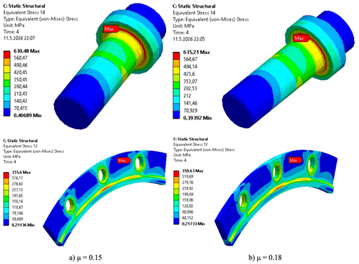
Fig. 9. Stress distributions for the bolt and
flange using a) μ
= 0.15 and b) μ =
0.18
Although this limited comparison
indicates that the strength-related stress results are not strongly affected
within this friction range, it should not be interpreted as a full friction
sensitivity study. The TLC margin remains directly dependent on the assumed
friction coefficient. Therefore, μ = 0.15 was retained as the conservative
baseline for the clamp-dependent margin evaluation.
4. CONCLUSIONS
This study presents
a traceable analytical-numerical workflow for high-temperature bolted flange
joints, linking torque definition, preload establishment, preload retention, local stress
interpretation, and margin-based assessment. The workflow explicitly verifies
preload, maps thermal conditions into the structural model, and evaluates joint
integrity using margins tied to specific physical limit states. This structure
improves transparency for design review and supports reuse on similar aerospace
hardware.
The
results indicate that elevated temperature robustness can often be improved by
controlling stiffness balance, limiting flange rotation, and preserving clamp
retention, rather than by increasing bolt strength alone. This emphasizes that
the system-level stiffness and contact evolution are key design drivers at high
temperature.
The
analytical framework is based on VDI 2230
Based
on these findings, two specific recommendations are made for future revisions
of VDI 2230 and NASA-STD-5020B. First, temperature-dependent preload correction
methodologies that explicitly couple differential thermal expansion with
elastic modulus reduction must be introduced for joints operating above 500°C.
Second, for complex bolted flange configurations in hot-section applications,
standard guidelines may benefit from recommendations for high-fidelity,
thermo-mechanically coupled 3D FEA rather than relying on overly simplified 1D
analytical bending assessments. The present study is limited to the
instantaneous thermo-elastic response of the joint. Time-dependent creep and
stress relaxation effects were not included in the analytical or numerical models
and should be considered in future long-term durability assessments.
Acknowledgements
This
work was supported by Scientific Research Projects Department of Istanbul
Technical University.
References
1. Reed Roger C. 2008. The
superalloys: fundamentals and applications. Cambridge university press. ISBN::
1139458639.
2. Bickford John H., Michael
Oliver. 2022. Introduction to the Design and Behavior
of Bolted Joints: Non-Gasketed Joints: Fifth Edition. CRC press. ISBN:: 9780429520709.
DOI: https://doi.org/10.1201/9780429243943.
3. Croccolo
Dario, Massimiliano De Agostinis, Nicolò
Vincenzi. 2012. „A contribution to the selection and calculation of screws in
high duty bolted joints”. International Journal of Pressure Vessels and
Piping 96-97: 38-48. ISSN 03080161. DOI:
https://doi.org/10.1016/j.ijpvp.2012.05.010.
4. Yu Qingmin, Honglei Zhou, Libin Wang. 2015. „Finite element analysis of
relationship between tightening torque and initial load of bolted connections”.
Advances in Mechanical Engineering 7(5): 1-8. ISSN: 1687-8132. DOI:
https://doi.org/10.1177/1687814015588477.
5. Greco A., A. De Luca, G.
Lamanna, R. Sepe. 2019. „Numerical Investigation on the Influence of Tightening
in Bolted Joints”. Procedia Structural Integrity 24: 746-757. ISSN: 24523216.
DOI: https://doi.org/10.1016/j.prostr.2020.02.066.
6. VDI 2230 Part 1: 2003. Systematic
calculation of high duty bolted joints: Joints with one cylindrical bolt.
Verein Deutscher Ingenieure VDI.
7. Giannella Venanzio, Raffaele
Sepe, Roberto Citarella, Enrico Armentani. 2021. „FEM Modeling
Approaches of Bolt Connections for the Dynamic Analyses of an Automotive
Engine”. Applied Sciences 11(10). ISSN: 2076-3417. DOI:
https://doi.org/10.3390/APP11104343.
8. Gray P.J., C.T. McCarthy.
2010. „A global bolted joint model for finite element analysis of load
distributions in multi-bolt composite joints”. Composites Part B:
Engineering 41(4): 317-325. ISSN: 13598368. DOI:
https://doi.org/10.1016/j.compositesb.2010.03.001.
9. Abid Muhammad. 2006.
„Determination of safe operating conditions for gasketed flange joint under
combined internal pressure and temperature: A finite element approach”. International
Journal of Pressure Vessels and Piping 83(6): 433-441. ISSN: 0308-0161.
DOI: https://doi.org/10.1016/J.IJPVP.2006.02.029.
10. Barrett Richard T. 1990. (NASA-RP-1228)
Fastener Design Manual.
11. ISO 16047: 2005. Fasteners
– Torque/Clamp Force Testing.
12. ASME PCC-1-2000. 2010. Guidelines
for Pressure Boundary Bolted Joint Assembly.
13. Eccles W., I. Sherrington, R.
D. Arnell. 2010. „Frictional changes during repeated tightening of zinc plated
threaded fasteners”. Tribology International 43(4): 700-707. ISSN: 0301679X.
DOI: https://doi.org/10.1016/j.triboint.2009.10.010.
14. Zhao Penghao, Jianhua Liu, Hao
Gong, Zhengyue Tan, Zhongtian
Lu. 2026. „Dynamic modeling of the rotor system with
bolted joints considering microscopic contact and nonuniform preloads”. Applied
Mathematical Modeling 155. ISSN: 0307904X. DOI:
https://doi.org/10.1016/J.APM.2025.116731.
15. Zhang Leizhi, Xin Wang, Lining
Ding, Jingyang Zhou, Jialin Liu, Zhishen
Wu. 2026. „Connection behavior and failure mechanisms
of FRP sleeved joints with bonded inserts versus conventional bolted joints”. Engineering
Structures 351. ISSN: 18737323. DOI:
https://doi.org/10.1016/J.ENGSTRUCT.2025.122031.
16. Li Yuqi, Bo Yang, Chuanmei Wen, Zhong Luo, Bing Li, Xuezhong
Fu, Yuanzhao Chen. 2025. „Dynamic analysis of the
lateral-torsional coupled vibration of a bolted joint rotor system considering
the varying contact state at mating interface”. Mechanical Systems and
Signal Processing 241. ISSN: 10961216. DOI:
https://doi.org/10.1016/J.YMSSP.2025.113508.
17. Hoseini
Sabzevari S.A., M.H. Jalal Kamali. 2026. „Looseness
monitoring of Multi-Bolt connection using acoustic emission”. Ultrasonics
160. ISSN: 18749968. DOI: https://doi.org/10.1016/J.ULTRAS.2025.107895.
18. Ma Shuai, Lunping
Li, Yifei Nan, Hongda Zhao, Yi Sun, Yongbin Dang.
2026. „Failure boundary analysis of bolt loosening under complex impact load”. Zhendong
yu Chongji/Journal of
Vibration and Shock 45(3): 294-302. ISSN: 10003835. DOI:
https://doi.org/10.13465/J.CNKI.JVS.2026.03.030.
19. Li Ling, Chenzhuo
Zhang, Yao Li, Jingjing Wang, Fu’an Cheng. 2025.
„Loosening behavior of bolt connection considering
contact stiffness of joint surface”. Zhendong yu Chongji/Journal of Vibration and Shock 44(19): 40-50.
ISSN: 10003835. DOI: https://doi.org/10.13465/J.CNKI.JVS.2025.19.005.
20. Valdez Rhandall, Edwin
Palacios, Christian Tutivén, Yolanda Vidal. 2025. „Bolt-loosening detection in
offshore wind turbines’ jacket-type supports”. Structural Health Monitoring
24(5): 2941-2957. ISSN: 17413168. DOI:
https://doi.org/10.1177/14759217241268522.
21. Cai Yunzhu, Yujie Xing, Qiang
Xie, Xiaowu Cheng. 2025. „Effects of bolt joint
loosening on the dynamic characteristics of electric angle steel transmission
tower”. Journal of Southeast University (English Edition) 41(2): 180-189.
ISSN: 10037985. DOI: https://doi.org/10.3969/J.ISSN.1003-7985.2025.02.007.
22. Mummadi
Anjireddy, Mallika Alapati, T. Omeshwari, Shivani Abboju, P. Arun, D. Venkatesh. 2025. „Loosened Bolt
detection in Steel joints using Deep Learning Techniques”. IFAC-PapersOnLine 59(8): 417-423. ISSN: 24058963. DOI:
https://doi.org/10.1016/J.PROSTR.2025.07.072.
23. Wu Tongyu, Yonggang
Kang, Shuaijia Kou, Zhipu
Tan, Zihao Wang, Guangyu Zhao, Bokuan
Fan. 2026. „Tensile strength and damage patterns of bolted interference-fit
joints in composite open-hole laminates based on acoustic emission monitoring”.
Engineering Failure Analysis 186. ISSN: 13506307. DOI:
https://doi.org/10.1016/J.ENGFAILANAL.2025.110508.
24. ZUO Duquan, Jie LIU, Yuejie CAO, Minghao ZHANG, Shaoqing JIN, Yaoming FU, Zengqiang CAO. 2026.
„A prediction model for axial installation force of interference-fit bolt in
CFRP bolted joint and its deformation mechanism of contact interface at
bolt-hole under static loading”. Chinese Journal of Aeronautics 39(3).
ISSN: 10009361. DOI: https://doi.org/10.1016/J.CJA.2025.103892.
25. Wang Yanran, Xumeng Xie, Qingshan Li, Wenjie Pan, Zhaozhao
Bai. 2026. „Research on Magneto-Acoustic Combined Stress Detection of Flange
Connection Bolts Under Eccentric Loading Conditions”. Journal of Nondestructive Evaluation 45(1). ISSN: 15734862. DOI:
https://doi.org/10.1007/S10921-025-01315-5.
26. Qi Liangjie, Ruofan Meng, Zheng Luo, Yihang Li, Ke Jiang, Jianyang Xue.
2026. „Axial tensile hysteretic performance and analytical model of joints in
prefabricated dual-column load-bearing hanger systems”. Engineering
Structures 348. ISSN: 18737323. DOI:
https://doi.org/10.1016/J.ENGSTRUCT.2025.121777.
27. Wang Xian Feng, Qian Xi Zhang,
Zhi Peng Fu, Wei Lun Wang, Jian Liu, Xiao Gang Zhang, Shan Bai Dong. 2025.
„Experimental and numerical study on connection joints applied to automatic
construction device”. Advanced Steel Construction 21(5): 458-475. ISSN: 1816112X.
DOI: https://doi.org/10.18057/IJASC.2025.21.5.8.
28. Ren Xiaoyang, Yaguang Dai, Zhicheng Dong, Ben Jia, Muwen
Niu, Meiying Zhao, Heyuan Huang. 2026. „Investigation
on mechanical behavior and damage mechanism of
T1000/BMI composite bolted joints under thermomechanical cycling of −80°C∼80°C”. Composites Part B:
Engineering 311. ISSN: 13598368. DOI:
https://doi.org/10.1016/J.COMPOSITESB.2025.113261.
29. Zheng Hanfang, Yujing Jiang, Xuezhen Wu, Sunhao Zhang. 2026.
„Shear performance degradation of bolted rock joint under corrosion-temperature
coupling”. Construction and Building Materials 511: 145305. ISSN: 09500618.
DOI: https://doi.org/10.1016/J.CONBUILDMAT.2026.145305.
30. Tofighi
Ali, Linbo Zhu, Abdel Hakim Bouzid. 2026. „Elastic
Interaction in Bolted Flange Joints During Hot Bolting and Disassembly”. Journal
of Pressure Vessel Technology 148(1). ISSN: 15288978. DOI:
https://doi.org/10.1115/1.4070157.
31. Wang Hui, Shidong
Nie, Bo Yang, Wei Jiang, Weilai Yao, Min Liu. 2025.
„Enhanced tying resistance of high-strength austenitic-stainless-steel bolted
web cleat connections after fire”. Journal of Constructional Steel Research
235. ISSN: 0143974X. DOI: https://doi.org/10.1016/J.JCSR.2025.109843.
32. Guo Xiaonong,
Xiong Duan, Jun Liu, Shaozhen Chen. 2025. „Study on
flexural behavior of aluminum
alloy portal frame beam-column joint at high temperature”. Thin-Walled
Structures 215. ISSN: 02638231. DOI:
https://doi.org/10.1016/J.TWS.2025.113477.
33. Kai LEI, WU Jingtao, DENG Wenliang. 2025. „Analysis of mechanical
properties of composite-metal bolted panel under thermo-mechanical coupling
condition”. Hangkong Xuebao/Acta
Aeronautica et Astronautica Sinica 46(21): 1-12.
ISSN: 10006893. DOI: https://doi.org/10.7527/S1000-6893.2025.32276.
34. Cong Zhiyuan, Zhefeng Yu, Dongjie Jiang. 2025.
„On the hysteretic response of mechanical strain induced by thermal stress in
fastened metal-composite hybrid structures during a temperature cycle”. Aerospace
Systems 8(3): 605-618. ISSN: 25233955. DOI:
https://doi.org/10.1007/S42401-024-00312-2.
35. Jiang Yulin, Hongyuan Cao, Chaofeng Li, Yazheng Zhao, Yunjun Wang, Jin
Zhou. 2025. „Thermo-elastic coupling modeling method
and analysis of a bolt-connected turbine rotor under non-uniform thermal
fields”. Mechanics Based Design of Structures and Machines 54(1). ISSN: 15397742.
DOI: https://doi.org/10.1080/15397734.2025.2605531.
36. Huang Zhen, Zhangqian Ye, Zhaojian Hu, Jiawei
Zhang, Chen Cao. 2024. „Study on the High-Temperature Mechanical Behavior and Parameters of Joints: a Case of a
Prefabricated Frame Tunnel”. KSCE Journal of Civil Engineering 28(9):
4158-4174. ISSN: 19763808. DOI: https://doi.org/10.1007/S12205-024-0131-7.
37. Bryndza
Guillian, Jérôme Tchoufang Tchuindjang, Fan Chen,
Anne Marie Habraken, Héctor Sepúlveda, Víctor Tuninetti, Anne Mertens, Laurent
Duchêne. 2025. „Review of the Microstructural Impact on Creep Mechanisms
and Performance for Laser Powder Bed Fusion Inconel 718”. Materials
18(2): 276. ISSN: 1996-1944. DOI: https://doi.org/10.3390/ma18020276.
38. Sugahara Tarcila, Antônio
Augusto Couto, Miguel Justino Ribeiro Barboza, Francisco Piorino Neto, Renata
Jesuina Takahashi, Danieli Aparecida Pereira Reis. 2022. „Creep and Mechanical Behavior Study of Inconel 718 Superalloy”. Materials
Research 25: e20210280. ISSN: 1516-1439. DOI:
https://doi.org/10.1590/1980-5373-MR-2021-0280.
39. Erklig
Ahmet, Ibrahim H Guzelbey, Abdulkadir Cevik. 2010. „Finite Element Analysis of
Finite Strain Elastoplastic Contact-Impact Problems”. Gazi University
Journal of Science 23(3): 327-338.
40. Sarı
Kadir, Hakan Dilipak. 2024. „A Software for Optimum Design of Laterally Loaded
Bolted Joints”. Gazi Üniversitesi Fen Bilimleri Dergisi Part C: Tasarım ve Teknoloji 12(1): 366-377. ISSN: 2147-9526. DOI:
https://doi.org/10.29109/gujsc.1385010.
41. Zhao Hua. 1998. „Stress
concentration factors within bolt-nut connectors under elasto-plastic
deformation”. International Journal of Fatigue 20(9): 651-659. ISSN: 0142-1123.
DOI: https://doi.org/10.1016/S0142-1123(98)00036-X.
42. Li Ying, Zhifeng
Liu, Yuezhen Wang, Ligang
Cai, Wenxiang Xu. 2019. „Research on preload of bolted joints tightening
sequence-related relaxation considering elastic interaction between bolts”. Journal
of Constructional Steel Research 160: 45-53. ISSN: 0143974X. DOI:
https://doi.org/10.1016/j.jcsr.2019.01.016.
43. Zheng Mingpo, Zhifeng Liu, Xing Yan, Nana Niu, Tao Zhang, Ying Li. 2022.
„Initial losing behavior of pre-tightening force for
threaded fastener during repeated tightening”. Engineering Failure Analysis
134. ISSN: 13506307. DOI: https://doi.org/10.1016/j.engfailanal.2021.106021.
44. Wang Y. Q., J. K. Wu, H. B.
Liu, K. Kuang, X. W. Cui, L. S. Han. 2017. „Analysis of elastic interaction
stiffness and its effect on bolt preloading”. International Journal of
Mechanical Sciences 130: 307-314. ISSN: 00207403. DOI:
https://doi.org/10.1016/j.ijmecsci.2017.05.032.
45. NASA-STD-5020. 2012. Requirements
for threaded fastening systems in spaceflight hardware measurement system
identification: metric/SI (English).
46. MIL-HDBK-60. 1990. Military
handbook threaded fasteners - tightening to proper tension.
47. Friedrich C., H. Hubbertz.
2014. „Friction behavior and preload relaxation of
fastening systems with composite structures”. Composite Structures
110(1): 335-341. ISSN: 02638223. DOI:
https://doi.org/10.1016/j.compstruct.2013.11.024.
48. Wang Jingze, Yanqi Li, Fuhong Dai. 2016. „A micromechanical relaxation model of
composite bolted connections based on viscoelastic theory”. Composite
Structures 146: 14-25. ISSN: 02638223. DOI:
https://doi.org/10.1016/j.compstruct.2016.02.059.
49. Finck David, Christian Seidel,
Joachim Hausmann, Thomas Rief. 2019. „Creep-induced screw preload loss of
carbon-fiber sheet molding
compound at elevated temperature”. Materials 12(21). ISSN: 19961944.
DOI: https://doi.org/10.3390/ma12213598.
50. Tran Van Thuy, Huu Loc Nguyen.
2026. „Experimental investigation of the influence of friction, surface
roughness and material hardness on the external load factor in threaded
joints”. PLOS ONE 21(1): e0340073. ISSN: 1932-6203. DOI:
https://doi.org/10.1371/JOURNAL.PONE.0340073.
Received 03.04.2026; accepted in
revised form 12.05.2026

Scientific
Journal of Silesian University of Technology. Series Transport is licensed
under a Creative Commons Attribution 4.0 International License