Article citation information:
Protsenko, V., Rusanov, S., Babiy, M., Kliuiev, O.,
Voitovych, O. Analysis of water transfer centrifugal pump shaft
dynamic loads under different operating modes. Scientific Journal of Silesian University of Technology. Series
Transport. 2026, 131, 177-188. ISSN:
0209-3324. DOI: https://doi.org/10.20858/sjsutst.2026.131.11
Vladyslav
PROTSENKO[1],
Sergiy RUSANOV[2],
Mykhailo BABIY[3],
Oleg KLIUIEV[4],
Olha VOITOVYCH[5]
ANALYSIS OF WATER TRANSFER CENTRIFUGAL PUMP SHAFT DYNAMIC LOADS UNDER
DIFFERENT OPERATING MODES
Summary. The article addresses the dynamics of an water
transfer centrifugal pump drive with a asynchronous electric motor operating on
a filled reservoir. A three-mass dynamic model of the drive has been
developed, and the equations of motion for the masses have been formulated.
Friction losses inside the pump, pipeline resistance, and the inertial
resistance of the fluid in the pipeline have been taken into account. The
torque of the asynchronous drive motor is described by the Kloss equation. The
numerical solution of the dynamic equations shows that the most dangerous
scenario in terms of the strength of the pump's main shaft and motor
overheating is startup with the delivery valve open, as overload here
approaches approximately 20 times the nominal value. It has been established
that during pump startup with the delivery valve closed, shaft overload can
reach 160%, while sudden opening of the valve on the delivery pipeline results
in 180%. It is shown that transient operating modes of the pump drive are
accompanied by intense torsional vibrations, which reduce shaft service life
and must be considered in refined calculations. The cases examined are of
practical value, as they underscore the need to follow pump operating
procedures.
Keywords: centrifugal
pump, shaft, dynamic load, torque, oscillations, failure, operation
1. INTRODUCTION
Centrifugal pumps are among the most
common devices in transport systems, including pipelines and marine vessels,
where they perform critical functions in ballast systems, cooling systems of
power units, and cargo systems of tankers. To ensure reliable operation of
pumps - particularly their most stressed components, such as shafts - it is
necessary to reduce dynamic loads in their drives. This can be achieved by
adhering to established maintenance and operational requirements. Operators and
engineering students often fail to realize how violations of operating rules
affect the performance and wear of components. This forms the basis for
studying the operational conditions influencing the service life of centrifugal
pump shafts.
|
|
|
|
Fig. 1. Photograph of the fatigue fracture
surface of the shaft |
Fig. 2. Photograph of the fatigue fracture
surface of the pump shaft |
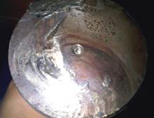
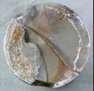
The most expensive and frequently
damaged components of centrifugal pumps are the main shafts, on which the
impeller and semi coupling of the motor coupling are mounted. Replacing a shaft
requires nearly complete disassembly of the pump, removal of the impeller and
bearings, resulting in equipment downtime and considerable human and material
resource costs.
Study [1] investigated the failure
of a centrifugal pump shaft after many operating cycles. Using chemical
analysis, microstructural analysis, and fractography, and employing the
modified Goodman criterion to evaluate fatigue stress, it was determined that a
fatigue crack initiated in the area of an existing stress concentrator - the
thread (Fig. 1). The study also noted insufficient fatigue strength under
fluctuating loads and recommended revising the thread geometry while accounting
for variable stresses. Study [2] analyzed shaft failure in a pump at a steel
plant after 2.5 years of operation near the keyway. Metallography, mechanical
testing, and geometric analysis of the keyway were employed. It was found that
even small deviations in keyway geometry can cause stress concentration and
fatigue crack initiation. The shaft material exhibited insufficient
heat-treatment quality, reducing fatigue strength and leading to crack
initiation and propagation under dynamic loading. Study [3] described the
failure of a circulation pump shaft in a chemical plant cooling system. Using
chemical and structural analysis and fractography, it was shown that
calcium-silicate inclusions on the shaft surface served as crack initiators,
which under cyclic dynamic loads resulted in fatigue fracture. Improved
material cleanliness and heat treatment were recommended. Study [4] analyzed
the failure of a condensate pump shaft at a thermal power station after 5 years
of operation. Visual inspection, microstructural and chemical analysis, and
fractography indicated that the failure was caused by stress concentration and
sulfide inclusions near the surface, leading to fatigue failure due to
torsional vibrations. Study [5] discussed the failure of slurry transport pump
shafts. Using chemical analysis, metallography, and mechanical testing, it was
found that improper heat treatment regimens caused reduced fatigue strength and
premature shaft failure. Similar results were obtained in [6], where poor
repair quality caused shaft failure two days after reassembly. Paper [7]
described six cases of shaft failure in cooling water pumps on a container
vessel and analyzed the two most recent ones. It was established that shafts
failed due to fatigue caused by dynamic loads at stress concentrators (keyways)
and improper material selection. Stress concentrators also caused shaft failure
in a multistage centrifugal pump [8], where it was shown that reducing stress
concentration through design modifications can increase shaft life under
torsional vibration. Modeling of a three-stage centrifugal water pump under
variable load was carried out in [9]. The study focused on the effect of
hydrodynamic forces on shaft fatigue stress and demonstrated that conventional
calculations underestimate dynamic loads. Regions of hydrodynamic pressure
concentration and cyclic loading were identified. The proposed approach was
recommended for pump shaft design under variable load. The fatigue failure of a
hydraulic coke-removal system pump shaft at a metallurgical plant was reported
in [10]. Metallography, chemical analysis, and fractography confirmed that
cracks developed due to cyclic torsional loading. Fatigue failure of a thermal
power station circulation water pump shaft was analyzed in [11]. Material
porosity was found to be the main cause of fatigue fracture. Study [12]
described fatigue failure of a centrifugal pump shaft in a diesel engine
cooling system, where the initial crack formed at a stress concentrator under
torsional vibrations. The study recommended accurate stress evaluation in
design calculations. Paper [13] described premature failure of an electric
submersible pump shaft in an oil field and recommended reducing shaft overload.
Research [14] summarized statistical data from 2015 to 2024 on pump failures in
the oil, gas, chemical, and water supply industries in Ukraine. It was found
that 78% of failures involved mechanical damage, 15% hydraulic, 5% electrical,
and 2% corrosion-related causes.
Summarizing the review, it can be
stated that regardless of the origin of fatigue cracks - foreign inclusions,
porosity, stress concentrators, or machining and heat-treatment defects - the
cause of crack formation lies in dynamic loads in the pump drive, which induce
shaft vibrations.
To perform refined dynamic
calculations, it is necessary to derive and solve the equations of motion for
the pump drive components under external torque disturbances from both the
motor driving and hydraulic resistance. Studies on the dynamics of centrifugal
pump drives are scarce; only [15] examines natural oscillations of vertical
pump drive components.
Thus, the purpose of this study is
to analyze the dynamics of a centrifugal pump drive under various operational
conditions.
Tasks of the study:
-
to develop a
dynamic model of a centrifugal pump drive and derive equations of motion for
its masses;
-
to formulate the
disturbance torque equations for both driving and resisting moments;
-
to describe the
main operational cases and specify initial conditions for the equations of
motion;
-
to select a
specific pump system for analysis and determine constant parameters;
-
to analyze dynamic
loads on the pump shaft by solving the derived system for characteristic
operating cases;
-
to rank the cases
in terms of their hazard to the static and fatigue strength of the pump shaft.
2. METHODOLOGY
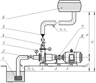
The schematic of the model pump
system is shown in Fig. 3. It includes a suction pipeline with inlet filter 1
and suction valve 2, through which the centrifugal pump 3 draws fresh water.
The discharge pipeline has a pressure valve 4 and a check valve 5 preventing
fluid backflow from tank 6. The pump 3 is driven by an asynchronous motor 8 via
an elastic coupling 7.
When developing and analyzing the dynamic model, materials from studies describing basic modeling principles [16], mass and force reduction [17], and examples of dynamic analysis [18] were used. The asynchronous motor characteristics can be approximated using the Kloss formula [20], despite the underlying complexity of electromagnetic interactions [19]. Inside a centrifugal pump, there are quite complex transient processes associated with the unsteady rotation of the fluid [21], here we use well-known materials [22] for internal losses in pump housing. Pipeline losses we definite according to standard hydromechanics [23, 24].
|
|
|
|
Fig. 3. Schematic diagram of a pump unit with
centrifugal pump and induction motor |
Fig. 4. Three-mass torsional dynamic model of
the pump driving |
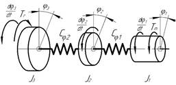
The dynamic model of the pump unit
is represented as a three-mass system (Fig. 4), where the driven mass J3 is formed by the pump
impeller, the intermediate mass J2
by the driven semicoupling of the flexible coupling, and the driving mass J1 by the electric motor
rotor and the driving semicoupling of the same coupling.
The masses are connected by elastic
elements - a shaft with torsional stiffness Сφ2 and a flexible coupling with torsional
stiffness Сφ1.
When developing the dynamic model,
the following assumptions were made:
-
the pipelines are
considered perfectly rigid;
-
the elastic
elements of the couplings have constant stiffness and zero damping;
-
the hydraulic
resistance coefficients in the pipeline and inside the pump do not depend on
the fluid velocity.
The system of motion equations for
such a system will be [12-14]:
|
|
(1) |
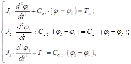
where φ1, φ2 and φ3 are the angular coordinates of the
respective masses; Тm is the electric motor torque; Тtr is the
resistance torque.
The torque of the asynchronous
electric motor by Kloss equation [20]:
|
|
(2) |
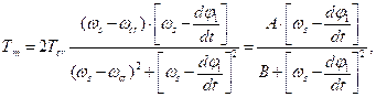
where Тcr is the critical torque; ωs is the synchronous rotor rotation
frequency;
ωcr is the critical rotor rotation
frequency.
The resistance torque  reduced to the impeller include disk friction
torque in the pump
reduced to the impeller include disk friction
torque in the pump  and load from the pipeline
  :
:
|
|
(3) |

Disc friction torque will be [17,
18]:
|
|
(4) |

where 2,4…2,7 is a coefficient that accounts
for losses from both impeller ends, increased friction in a real pump compared
to a model disk, and friction losses in the seal;  is the friction coefficient depending on the
fluid flow regime inside the pump and the magnitude of the ratio of the gap
between the impeller ends and the housing (Re is the Reynolds
criterion); R is the impeller radius.
is the friction coefficient depending on the
fluid flow regime inside the pump and the magnitude of the ratio of the gap
between the impeller ends and the housing (Re is the Reynolds
criterion); R is the impeller radius.
The load acting on the pump impeller
from the pipeline side consists of the torque Тst due to the static head of the pipeline, the
torque Тtr
caused by the hydraulic resistance in the pipeline, and the torque Тin resulting from the inertia of the
liquid in the filled pipe:
|
|
(5) |

Torque Тst from static head Нst will be:
|
|
(6) |
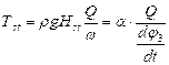
The torque from hydraulic resistance
in the pipeline reduced to pump impeller J3
[19]:
|
|
(7) |

where dsc
is the suction pipeline diameter; dds
is the discharge pipeline diameter; lsc
is the suction pipeline length; lds
is the discharge pipeline length; ξ are local resistance coefficients
(valves, filters); λ is the Darcy coefficient.
For torque Тin from static inertial head Нin we will have:
|
|
(8) |

Taking into account pump efficiency
value η = 0,8, we
will get expression for pipeline resistance torque, reduced to pump impeller J3:
|
|
(9) |

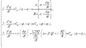
Taking into account the recorded
disturbing torques, the resulting dynamic model can be expressed by the
following system of equations (10).
|
|
(10) |
The highest loads on the pump shaft
may occur under the following operation conditions:
- starting the pump
motor without load when the discharge valve is closed (initial conditions: at t = 0;  );
);
- opening the discharge valve of the pump while
the motor is running (initial conditions: at t = 0; 

 . The
steady-state angular velocity ω0 of
the system before opening the discharge valve is determined by solving system
(10) at
. The
steady-state angular velocity ω0 of
the system before opening the discharge valve is determined by solving system
(10) at  );
);
- starting the pump motor with the opened
discharge valve (a mode prohibited by operating regulations but possible in
practice; initial conditions: at t =
0;  ).
).
When opening the discharge valve on
a running pump, according to the electrical RC
analogy, the change in flow rate Q is
calculated using expression (11) [20].
When starting the pump with the
discharge valve open, Q is determined
using expression (12) [19].
|
|
(11) |
|
|
|
|
|
(12) |


where ωn is the nominal angular velocity of the motor; τ is the relaxation time of dynamic processes in the pipeline.
Calculations were performed using the example
of a pump unit that includes a centrifugal pump with capacity Qn
= 400 m³/h = 0.1111 m³/s, driven by an asynchronous
motor P = 90 kW at nn = 1440 rpm through a flexible pin-bush
coupling. The pump operates on a pipeline with diameters dsc = 0.20 m
and ddc = 0.15 m, length lsc = 20 m, ldc = 45 m, transferring fresh water (ρ = 1000 kg/m³) through a filter to a tank
at height Нst = 20 m from the water free surface. The pump
impeller has mass m = 42 kg
and radius R = 0.203 m.
For the described pump unit, the
constants used will have next values:  ,
,  ,
,  ,
,  ,
,  ,
,  , α = 196200 Pa, β = 30978014 Pa·s2/m2, γ = 3183099 kg/m4, Re = 7×10⁶, cf = 0,002, χ = 0,0019 N·m s2/rad2,
ψ = 0,00072 m3/rad,
, α = 196200 Pa, β = 30978014 Pa·s2/m2, γ = 3183099 kg/m4, Re = 7×10⁶, cf = 0,002, χ = 0,0019 N·m s2/rad2,
ψ = 0,00072 m3/rad,
 The moments of inertia of masses and torsional
stiffnesses will be: J1 = 0,55 kg·m2,
J2 = 0,15 kg·m2, J3 = 0,87 kg·m2, Сφ1 =
80000 N·m/rad, Сφ2 =
166154 N·m/rad.
The moments of inertia of masses and torsional
stiffnesses will be: J1 = 0,55 kg·m2,
J2 = 0,15 kg·m2, J3 = 0,87 kg·m2, Сφ1 =
80000 N·m/rad, Сφ2 =
166154 N·m/rad.
The results of solving the system of
equations (10) for the described operating conditions are presented as graphs
of the flow rate  , the
angular velocities
, the
angular velocities  of the corresponding masses, the motor torque
  , and the
shaft torque
, and the
shaft torque  .
.
3. RESULTS AND
DISCUSSION
Fig. 5…Fig. 7 show the respective
plots obtained from the numerical solution of system (10).
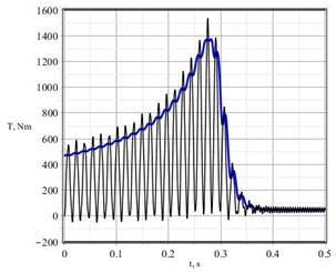
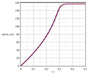
Analysis of the graphs in Fig. 5
indicates that the pump acceleration without load occurs in approximately 0.35
s, during which the motor develops sufficient torque Tm to overcome the disc friction torque Tdf, and the system reaches a
steady angular velocity of ω0 = 156.6 rad/s. The shaft overload during such a
startup is characterized by the dynamic factor, defined as the ratio of the
maximum torque Tmax to the
nominal torque Tn: Kd = Tmax/Tn
= 2.60, where the nominal torque is Tn
= 590 N·m.
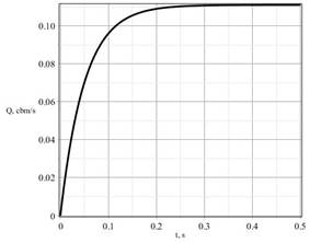
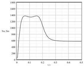
When the discharge valve is opened
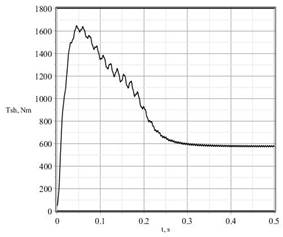
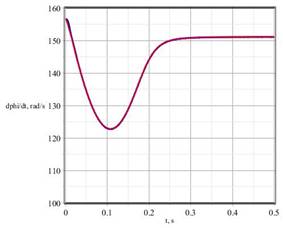
on a running pump (Fig. 6), the transient process will last approximately 0.3
s, with shaft overload reaching 180%, corresponding to a maximum torque in the
shaft of 1650 N·m. The angular velocities of the rotating masses decrease from ω0 = 156.6 rad/s to approximately ω = 122 rad/s
upon valve opening, followed by a return to the nominal angular velocity ωn = 150.8 rad/s.
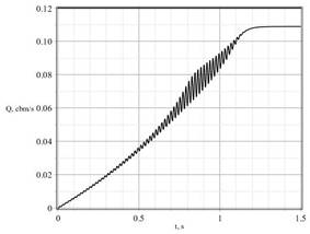
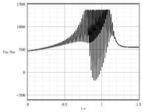
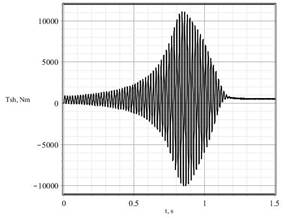
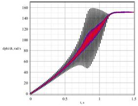
The most dangerous scenario is starting the pump with
the opened discharge valve (Fig. 7). Here, the system exhibits classic positive
feedback behavior until the critical angular velocity is reached (approximately
at 0.85 s), which accounts for the significant danger of starting in this
configuration. The frequency of the growing oscillations depends on the
system's natural frequency, the moment of inertia of the rotating masses, and
the slope of the engine's starting characteristic curve. In this case, shaft
overload reaches 1800%, which is clearly dangerous for its structural integrity
and may lead to plastic deformation. This is naturally accompanied by engine
overload, with potential overheating due to the acceleration time being
extended fourfold to 1.35 s.
|
|
|
||
|
a) |
b) |
||
|
Fig. 5. Graphs of torque variations (a):
motor torque (blue) and shaft torque (black), |
|||
|
|
|
||
|
a) |
b) |
||
|
|
|
||
|
c) |
d) |
||
|
Fig. 6. Graphs of changes in flow rate (a),
engine torque (b) and shaft torque (c), 4. CONCLUSION 1)
The dynamic
behavior of a centrifugal pump with an induction drive motor operating under
flooded suction conditions has been analyzed. A three-mass dynamic model of
the drive was developed, and the equations of motion for the masses and
disturbing torques were formulated. The equations were solved for three
characteristic cases: pump startup with a closed discharge valve, valve
opening during operation, and pump startup with an opened valve. 2)
It has been
shown that the most critical condition, in terms of the pump main shaft
strength and motor overheating, is startup with the discharge valve opened.
Under this condition, the shaft dynamic factor may reach Kd = 19, and the startup duration increases nearly
fourfold compared to startup with a closed discharge pipeline. This behavior
is evidently influenced by the presence of liquid-filled piping, which
imposes additional inertial loading. 3)
During startup
with the discharge valve closed, the shaft dynamic factor may reach Kd =2.60, and when the
discharge valve is opened during operation, Kd =2.80. These values correspond to the minimum
safety factor that should be incorporated in the strength design of the pump
drive. 4)
In all analyzed
cases, the transient operation modes of the pump drive are accompanied by
high-frequency torsional oscillations, which reduce the service life of
couplings and shafts. These effects should be accounted for in refined
dynamic calculations. 5)
The analyzed
cases have practical value as illustrative didactic materials demonstrating
actual pump operation rules and can be used in the training of maintenance
engineers. Another important application is the use of the formulated motion
equations for analyzing transient modes in the design of centrifugal pump
drives, particularly for identifying methods to reduce dynamic loads in their
drivetrains. |
|||
|
|
|
||
|
a) |
b) |
||
|
|
|
||
|
c) |
d) |
||
|
Fig. 7. Graphs of changes in flow rate (a),
engine torque (b) and shaft torque (c), |
|||
References
1. Tamin M., M.A. Hamzah. 2017. “Fatigue Failure Analysis of a Centrifugal Pump Shaft”. In: Failure Analysis and Prevention. InTech: 2-15. DOI: 10.5772/intechopen.70672.
2. Roy A., P. Palit, S. Das, G. Mukhyopadyay. 2020. „Investigation of Torsional Fatigue Failure of a Centrifugal Pump Shaft”. Engineering Failure Analysis 112. No 104511. DOI: 10.1016/j.engfailanal.2020.104511.
3. Jiang C., K. Tao, J. Wang, W. Wang. 2020. „Fracture Failure Analysis of the Pump Shaft”. E3S Web Conf. 213. No 03010. DOI: 10.1051/e3sconf/202021303010.
4. Ghanem M. 2018. „Failure Analysis of Condensate Pump Shaft in Power Plant”. Key Engineering Materials 786: 314-318. DOI: 10.4028/www.scientific.net/KEM.786.314.
5. Das G., A.N. Sinha, S.K. Mishra, D.K. Bhattacharya. 1999. „Failure Analysis of Counter Shafts of a Centrifugal Pump”. Engineering Failure Analysis 6(4): 267-276. DOI: 10.1016/S1350-6307(98)00037-5.
6. Gejdoš Р., L. Klakurková, M. Juliš. 2020. „Metallographic Analysis of Stainless Steel Inner Shaft of Centrifugal Pump”. Defect and Diffusion Forum 405: 223-228. DOI: 10.4028/www.scientific.net/DDF.405.223.
7. Papageorgiou D.G., K. Kovsenoglou, P. Bournelis, C. Medrea. 2018. „Fracture Analysis of a Cooling Water Pump Shaft”. MATEC Web of Conferences 188. No 04022. DOI: 10.1051/matecconf/201818804022.
8. Hua M., C. Cao, Y. Cai, J. Ge, F. Zhong, J. Mao. 2023. „Failure Analysis and Structural Fatigue Resistance Design of Multistage Centrifugal Pump Shaft”. Engineering Failure Analysis 153. No 107545. DOI: 10.1016/j.engfailanal.2023.107545.
9. Yadeta L., H.G. Lemu, A.K. Tadese. 2025. „Fluid Structure Interaction Induced Fatigue Stress Analysis of Multi-Stage Centrifugal Water Pump Shaft Under Varying Load Condition”. J Braz. Soc. Mech. Sci. Eng. 47. No 395. DOI: 10.1007/s40430-025-05703-w.
10. Zhai J.-m., X. Shang, L. Kong. 2021. „Fatigue Failure Analysis of Pump Shaft of a Hydraulic Coke Removal System”. J. Fail. Anal. and Preven. 21: 861-869. DOI: 10.1007/s11668-021-01124-8.
11. Hamid A., S. Nugroho, G. Dwi, H. Khaeroman. 2018. „Failure Analysis of Shaft Circulating Water Pump (CWP) Used in Power Plant”. MATEC Web of Conferences 159. No 02027. DOI: 10.1051/matecconf/201815902027.
12. Saiful W., H. Husaini, A. Nurdin. 2021. „Failure Analysis on the Fracture Shaft of a Centrifugal Pump Used for Diesel Engine Cooling System”. Key Engineering Materials 892: 107-114. DOI: 10.4028/www.scientific.net/KEM.892.107.
13. Pratiwi D., Y. Yudianto, A. Mataram, A. Prakoso. 2023. „Shaft Premature Failure Analysis in Electrical Submersible Pump System: Case Study from Muara Enim, South Sumatra, Indonesia”. Journal of Mechanical Science and Engineering 9(1).: 7-13. DOI: 10.36706/jmse.v9i1.71.
14. Morshch I.V. 2025. „Analysis of the Causes of Damage to Centrifugal Pumps During Operation and Methods of Their Elimination”. Problems of Tribology 115: 60-65. DOI: 10.31891/2079-1372-2025-115-1-60-65.
15. Chandra H., M. Luthfi, F. Lamin, A.
Ariffin. 2018. „Evaluation of Torsional Vibration on Vertical-Type Centrifugal
Pump Shaft”. Journal of Mechanical
Engineering 7(1): 167-175.
Available at: https://ir.uitm.edu.my/id/eprint/41508/1/41508.pdf
16. Komarov M.S. 1969. Dynamics of Mechanisms and Machines. Moscow: Mashinostroenie.
17. Loveikin V.S., Romasevych Yu.O.
2013. Dynamics of Machines. Kyiv: CP „KOMPRINT”.
18. Kolesnyk N.P. 1985. Calculations of Construction Cranes. Kyiv: Vyshcha Shkola.
19. Klyuchev V.I. 1971. Limitation of Dynamic Loads of Electric Drive. Moscow: Energiya.
20. Koljčević N., Ž. Fuštić, M. Ćalasan 2020. „Analytical Solution for Determination of Induction Machine Acceleration Based on Kloss Equation”. Serbian Journal of Electrical Engineering 17: 247-256. DOI: 10.2298/SJEE2002247K.
21. Ivchenko V. 2019. „On the unsteady rotating fluid flow in a uniformly rotating or fixed vertical cylinder”. European Journal of Physics 41(3). DOI: 10.1088/1361-6404/ab531e.
22. Lomakin A.A. 1966. Centrifugal and Axial Pumps. Moscow-Leningrad: Mashinostroenie.
23. Pritchard P.J., J.W. Mitchell. 2015. Fox and McDonald’s Introduction to Fluid Mechanics. 9th ed. John Wiley & Sons.
24. Crane Co. 1982. Flow of Fluids
through Valves, Fittings and Pipes. Metric Edition-SI Units. Technical
Paper No. 410M, Crane Co., New York.
Received 07.12.2025; accepted in
revised form 23.04.2026

Scientific
Journal of Silesian University of Technology. Series Transport is licensed
under a Creative Commons Attribution 4.0 International License