Article
citation information:
Vilchez,
A., Rodriguez, C.V., Cervan, D. Conceptual design of an unmanned aerial vehicle with a
fire extinguisher ball dropping system for forest firefighting. Scientific Journal of Silesian University of
Technology. Series Transport. 2026, 130,
257-283. ISSN: 0209-3324. DOI: https://doi.org/10.20858/sjsutst.2026.130.15
Antonio VILCHEZ[1],
Christian Vladimir RODRIGUEZ[2],
Dheybi CERVAN[3]
CONCEPTUAL DESIGN
OF AN UNMANNED AERIAL VEHICLE WITH A FIRE EXTINGUISHER BALL DROPPING SYSTEM FOR
FOREST FIREFIGHTING
Summary. This study presents the
conceptual design of a fixed-wing Unmanned Aerial Vehicle (UAV) equipped with a
fire-extinguishing ball deployment system for forest firefighting. The UAV
design includes a wingspan of 3.250 m and a length of 3.075 m, using the
NACA 6412 airfoil and a high-wing configuration to enhance aerodynamic
stability. The fuselage and tail dimensions, including horizontal and vertical
stabilizers, were optimized for aerodynamic efficiency. The UAV carries a payload
of 13.5 kg, consisting of nine fire-extinguishing balls with a diameter of 152
mm each, providing a total effective coverage area of approximately 90 m².
This configuration enables rapid and targeted suppression of ignition points in
remote areas affected by wildfires during their growth or declining stages.
Aerodynamic performance was evaluated using Computational Fluid Dynamics (CFD)
simulations at 30 m/s and angles of attack (AoA) of 0°, 5°, 10°, 15°, and 20°.
The UAV achieves a maximum take-off weight of 76.5 kg at an optimal AoA of
7.73°, while the best lift-to-drag ratio (L/D = 29.165) occurs at 5°. Pressure
and velocity contours confirm stable flight up to 10° AoA, with stall behavior
starting between 15° and 20°. Operational feasibility was assessed for remote
regions such as the Amazon, with a take-off distance of 214.3 m and 317.2 m
required to clear a 50-ft obstacle. These results demonstrate that the UAV can
safely and efficiently deliver fire-extinguishing payloads in areas with
limited accessibility, reducing the need for manned firefighting aircraft and
providing a safer alternative for forest fire management.
Keywords: fire extinguisher ball system, firefighting UAV, CFD,
conceptual design
1. INTRODUCTION
Wildland
fires represent a complex environmental and technological challenge that
demands rapid detection, precise intervention, and efficient resource
allocation. The suppression of these events involves not only logistical
coordination but also the deployment of aerial systems capable of operating
under unstable atmospheric conditions, elevated temperatures, and difficult
terrain.
In
September 2024, Peru recorded 180 forest fires across the regions of Amazonas,
Cajamarca, San Martín, Apurímac, Piura, Ucayali, and La Libertad.
Traditionally, firefighting efforts rely on the use of water buckets attached
to Mi-17 helicopters, which collect water from nearby lakes or rivers. However,
the Peruvian Army operates only 16 helicopters, while the Air Force has 9,
making it difficult to address this growing challenge effectively [1]. A straightforward
solution would be to purchase additional firefighting helicopters, particularly
Mi-17 units. Nevertheless, with an estimated cost of 32 million dollars per
aircraft, such an investment represents a considerable financial burden,
especially when the helicopters would be dedicated solely to this purpose. This
limitation raises the following research question: What is the most suitable
conceptual design for an unmanned aerial vehicle capable of assisting in forest
fire suppression?
In
recent years, advances in unmanned aerial technology have opened new
possibilities for supporting firefighting strategies through autonomous
monitoring, targeted suppression, and reduced exposure of human crews to
hazardous environments. Sevzinski et al. [2] determined that only three Mi-17
helicopters equipped with Bambi Buckets are required to extinguish a 240
m² fire. Sousa and Gamboa [3] developed a forest fire detection algorithm
implemented on an Unmanned Aerial Vehicle (UAV) equipped with video cameras to
identify high-risk areas. Similarly, Wu et al. [4] presented a mathematical
model to estimate the optimal number of drones needed to suppress forest fires
in suburban areas of Hangzhou, China. Results from 72 simulations indicated an
8% reduction in fire-related losses. Kau et al. [5] proposed the conceptual
design of a firefighting helicopter named “FireWasp,” featuring a 15.2 m
wingspan and 4.2 m height, remotely controlled and capable of carrying up to
730 tons of water. Sharma [6] integrated a fire-extinguishing ball system into
a rotary-wing UAV, which received a 97.22% approval rating in its evaluation.
Pawar et al. [7] designed a hexacopter equipped with a high-resolution camera
and a ball-based fire suppression system capable of collecting and deploying
extinguishing spheres. De Moura [8] proposed the use of combat UAVs equipped
with thermal cameras to detect potential fire hazards. Dieteren [9] identified
several business cases for UAV-based firefighting applications, suggesting the
deployment of UAV swarms equipped with cameras, fire-extinguishing ball
systems, and detection sensors (“sniffers”). Furthermore, Aydin et al. [10]
examined the potential of integrating fire-extinguishing balls into a
drone-based system supported by remote sensing technologies as a complement to
traditional firefighting. Their proposed system consists of three UAV types: a
scouting UAV to detect fires and monitor risks near infrastructure or
firefighting brigades, a communication UAV to maintain coordination, and an
extinguishing UAV capable of autonomously releasing heat-activated,
eco-friendly fire-extinguishing balls.
For
this reason, designing a UAV platform for forest fire suppression in different
regions of Peru is particularly relevant, as it offers a considerably lower
cost compared to acquiring dedicated firefighting aircraft. Moreover, UAVs
provide a safer and more accessible alternative, reducing the risks faced by
firefighters in hazardous environments. Unlike manned helicopters, UAVs do not
require an onboard pilot, since they can be remotely operated. Previous studies
suggest that fire-extinguishing spheres are often more effective than
water-based methods, as the use of Bambi Buckets depends on the availability of
nearby water sources, an impractical condition for most UAVs.
The
primary objective of this work is to propose the conceptual design of a
fixed-wing UAV equipped with a fire-extinguishing sphere release system for
forest firefighting. Specifically, this study develops the aerodynamic design
parameters of the UAV, designs the sphere release mechanism, and performs
Computational Fluid Dynamics (CFD) simulations at different angles of attack
(AoA = 0°, 5°, 10°, 15°, and 20°) and at an air speed of 30 m/s to determine
lift (![]() ) and drag (
) and drag (![]() ) coefficients.
) coefficients.
This
research offers both practical and academic contributions. From an operational
perspective, it provides the Peruvian Air Force with an alternative to reduce
reliance on helicopters during firefighting operations. From an academic
perspective, it contributes to UAV innovation by integrating aerodynamic
analysis, CAD modeling, and CFD simulations. The knowledge generated may guide
the development of next-generation firefighting UAVs, particularly for
deployment in remote areas that are inaccessible to conventional methods.
2. METHODOLOGY
2.1. UAV aerodynamic design
The conceptual design of the UAV is
based on aerodynamic design equations that depend on the aircraft’s geometry.
For this reason, a set of formulas was selected to calculate the main
aerodynamic characteristics of the proposed system, following the methodology
described by Artamonova et al. [11]. The geometric parameters were determined
for the primary UAV components, namely the wing, fuselage, horizontal
stabilizer and vertical stabilizer.
2.1.1. Case study
The proposed UAV is intended for
operation in jungle environments affected by wildfires in their growth or
declining stages. However, in this study, it is specifically adapted for
extinguishing fires in remote and spatially constrained areas characterized by
limited water availability and dense vegetation. The selected case study area
is Mariscal Cáceres, located in the San Martín region of Peru. This zone lies
at an altitude between 350 and 450 m.a.s.l., with high forest density,
restricted ground access, and mountainous terrain, which prevents the use of
vehicles by firefighters. Due to the scarcity of water sources in the region,
the “Bambi Bucket” method would be ineffective for combating the wildfires
frequently reported by Aliaga Nestares et al. [12].
2.1.2. Geometric wing parameters
The wing aspect ratio (![]() ) is defined
as the ratio between the squared of the wingspan (
) is defined
as the ratio between the squared of the wingspan (![]() , m) and the
wing surface area (
, m) and the
wing surface area (![]() , m2).
, m2).
![]() (1)
(1)
The thickness-to-chord (![]() ) is the
relation between the wing root chord (
) is the
relation between the wing root chord (![]() , m) and the
wing tip chord (
, m) and the
wing tip chord (![]() , m).
, m).
![]() (2)
(2)
The quarter-chord sweep angle (![]() , deg) is a
parameter that depends on
, deg) is a
parameter that depends on ![]() and
and ![]() . This angle
is required for the calculation of
the
. This angle
is required for the calculation of
the ![]() and
and ![]() polar curve.
polar curve.
![]() (3)
(3)
#12#
![]() (4)
(4)
Where ![]() is the wing area (m2).
is the wing area (m2).
2.1.3. Geometric parameters for horizontal and
vertical stabilizers
The horizontal (![]() ) and
vertical (
) and
vertical (![]() ) stabilizer
aspect ratios are calculated in the same manner as for ʎ, using the square
of the horizontal (
) stabilizer
aspect ratios are calculated in the same manner as for ʎ, using the square
of the horizontal (![]() , m) and
vertical (
, m) and
vertical (![]() , m)
stabilizer spans, and the horizontal (
, m)
stabilizer spans, and the horizontal (![]() , m2)
and vertical (
, m2)
and vertical (![]() , m2)
stabilizer surface areas, respectively.
, m2)
stabilizer surface areas, respectively.
![]() (5)
(5)
#12#
![]() (6)
(6)
Next, the horizontal (![]() ) and
vertical (
) and
vertical (![]() ) stabilizer
thickness-to-chord ratios and the quarter-chord sweep angle of the horizontal (
) stabilizer
thickness-to-chord ratios and the quarter-chord sweep angle of the horizontal (![]() , deg) and
vertical (
, deg) and
vertical (![]() , deg)
stabilizers are computed.
, deg)
stabilizers are computed.
![]() (7)
(7)
![]() (8)
(8)
![]() (9)
(9)
![]() (10)
(10)
Where ![]() and
and ![]() are the wing root chords of the horizontal and
vertical stabilizers (m), and
are the wing root chords of the horizontal and
vertical stabilizers (m), and ![]() and
and ![]() are the wing tip chords of the horizontal and
vertical stabilizers (m).
are the wing tip chords of the horizontal and
vertical stabilizers (m).
2.1.4. Geometric parameters for fuselage
The fuselage aspect ratio (![]() ) is defined
as the ratio between the fuselage length (
) is defined
as the ratio between the fuselage length (![]() , m) and the
fuselage diameter (
, m) and the
fuselage diameter (![]() , m).
, m).
![]() (11)
(11)
The wet fuselage area (![]() , m2)
is defined as the exposed surface of the fuselage once assembled with the other
components (wing and tail). It is estimated using
, m2)
is defined as the exposed surface of the fuselage once assembled with the other
components (wing and tail). It is estimated using ![]() ,
, ![]() and
and ![]() .
.
 (12)
(12)
2.1.5. Aerodynamic parameters
To construct the polar curve, it is
necessary to determine the estimated UAV velocity (![]() , m/s),
which is obtained from the product of the critical Mach number (
, m/s),
which is obtained from the product of the critical Mach number (![]() ) and the
speed of sound at the estimated cruise altitude of the UAV (
) and the
speed of sound at the estimated cruise altitude of the UAV (![]() , m/s).
, m/s).
![]() (13)
(13)
![]() refers to the estimated flight condition at
which the airflow over a portion of the wing first reaches the speed of sound.
This parameter is determined using the thickness to chord ratio (
refers to the estimated flight condition at
which the airflow over a portion of the wing first reaches the speed of sound.
This parameter is determined using the thickness to chord ratio (![]() ), the
relative Mach number (
), the
relative Mach number (![]() ) and the
mean aerodynamic chord (
) and the
mean aerodynamic chord (![]() , m).
, m). ![]() and
and ![]() are the maximum airfoil thickness (m) and
local chord length (m), respectively.
are the maximum airfoil thickness (m) and
local chord length (m), respectively.
 (14)
(14)
![]() is calculated based on the relations
previously defined.
is calculated based on the relations
previously defined. ![]() is calculated using the wing profile
coefficient (
is calculated using the wing profile
coefficient (![]() ) and the
relative wing lift coefficient (
) and the
relative wing lift coefficient (![]() ).
).
 (15)
(15)
![]() (16)
(16)
Based on these parameters, the polar
curve for ![]() and
and ![]() can be calculated for UAV cruise flight. The
incidence angle (
can be calculated for UAV cruise flight. The
incidence angle (![]() , deg)
varies depending on the specific UAV configuration.
, deg)
varies depending on the specific UAV configuration.
 (17)
(17)
The blade polar coefficient (![]() ) requires
the effective wing aspect ratio (
) requires
the effective wing aspect ratio (![]() ).
).
![]() (18)
(18)
2.2. Fire extinguisher ball system design
2.2.1. Maximum take-off weight
It is necessary to calculate the
maximum take-off weight (![]() , N) to
properly design the ball release system.
, N) to
properly design the ball release system.
![]() (19)
(19)
Where ![]() is the cargo load (N), i.e., the
fire-extinguishing balls in this case,
is the cargo load (N), i.e., the
fire-extinguishing balls in this case, ![]() is the fuel mass (N), and
is the fuel mass (N), and ![]() represents the empty weight of the UAV (N), as
described by Raymer [13]. The calculation of the
represents the empty weight of the UAV (N), as
described by Raymer [13]. The calculation of the ![]() depends on the mission profile, defined as the
complete distance the UAV must cover from the base to the fire-affected area,
where the spheres are released, and then back to the base. Figure 1 illustrates
the UAV mission profile, which begins at the base, climbs to cruising altitude,
descends to the fire area to release the balls, ascends again to return to the
base, recharges the cabin compartment, and then repeats the mission cycle.
depends on the mission profile, defined as the
complete distance the UAV must cover from the base to the fire-affected area,
where the spheres are released, and then back to the base. Figure 1 illustrates
the UAV mission profile, which begins at the base, climbs to cruising altitude,
descends to the fire area to release the balls, ascends again to return to the
base, recharges the cabin compartment, and then repeats the mission cycle.
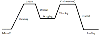
Fig. 1. UAV mission profile
To determine ![]() and
and ![]() , it is
necessary to express them as fractions of the take-off weight (
, it is
necessary to express them as fractions of the take-off weight (![]() , N), as
shown in the following equation.
, N), as
shown in the following equation.
![]() (20)
(20)
To determine ![]() , historical
data are used.
, historical
data are used.
![]() (21)
(21)
Where ![]() represents the UAV material; its value is 0.95
for composite and 1 for aluminum. In this research, composite material is
selected for the design and CFD analysis, as it represents 95% of the weight of
an aluminum UAV [14].
represents the UAV material; its value is 0.95
for composite and 1 for aluminum. In this research, composite material is
selected for the design and CFD analysis, as it represents 95% of the weight of
an aluminum UAV [14]. ![]() and
and ![]() coefficients are selected according to the UAV
model design. Table 1 presents the values of
coefficients are selected according to the UAV
model design. Table 1 presents the values of ![]() and
and ![]() coefficients used to estimate
coefficients used to estimate ![]() .
.
Tab.
1
![]() and
and ![]() coefficients for different aircraft models
[14]
coefficients for different aircraft models
[14]
|
Aircraft model |
|
|
|
Glider – powered |
0.83 |
-0.05 |
|
Glider - no powered |
0.88 |
-0.05 |
|
Homebuilt - metal / wood |
1.11 |
-0.09 |
|
Homebuilt - composite |
1.07 |
-0.09 |
|
General aviation - single engine |
2.05 |
-0.18 |
|
General aviation - twin engine |
1.4 |
-0.10 |
|
Agricultural aircraft |
0.72 |
-0.03 |
|
Twin turboprop |
0.92 |
-0.05 |
|
Amphibious aircraft |
1.05 |
-0.05 |
According to Jimenez et al. [15],
for a medium-sized fixed-wing UAV, the value of ![]() is 0.96 and the value of
is 0.96 and the value of ![]() is -0.06, based on historical data. In
addition, Diogo and Fernandes [16] estimated
is -0.06, based on historical data. In
addition, Diogo and Fernandes [16] estimated ![]() for 98 medium-sized fixed-wing UAVs with
combustion engine propulsion systems, finding values ranging from 0.44 to 0.63.
Based on the mission profile,
for 98 medium-sized fixed-wing UAVs with
combustion engine propulsion systems, finding values ranging from 0.44 to 0.63.
Based on the mission profile, ![]() is divided into flight segments. Table 2
presents the corresponding values and equations for each segment.
is divided into flight segments. Table 2
presents the corresponding values and equations for each segment.
Tab.
2
Values of ![]() at different flight
segments [16]
at different flight
segments [16]
|
Segment |
|
|
1. Take-off |
0.970 |
|
2. Climbing |
0.985 |
|
3. Cruise |
|
|
4. Descent |
1.000 |
|
5. Dropping |
|
|
6. Climbing |
0.985 |
|
7. Cruise (base) |
|
|
8. Descent |
1.000 |
|
9. Landing |
0.995 |
Where ![]() is the range (m),
is the range (m), ![]() is the specific fuel consumption (kg/N.s),
is the specific fuel consumption (kg/N.s), ![]() is the gravitational acceleration (9.81 m/s2),
and
is the gravitational acceleration (9.81 m/s2),
and ![]() is the lift-to-drag ratio, calculated using
the wing wet area (
is the lift-to-drag ratio, calculated using
the wing wet area (![]() , m2)
and
, m2)
and ![]() .
.
![]() (22)
(22)
![]() (23)
(23)
Where ![]() is the fuel consumption per unit of power
(kg/W.s), and
is the fuel consumption per unit of power
(kg/W.s), and ![]() is the propeller propulsive efficiency. The
value of
is the propeller propulsive efficiency. The
value of ![]() is 0.8, while
is 0.8, while ![]() is 0.068 kg/kW.h (or 0.2448x10⁻⁶
kg/W.s) for an internal combustion engine with a constant-speed propeller.
is 0.068 kg/kW.h (or 0.2448x10⁻⁶
kg/W.s) for an internal combustion engine with a constant-speed propeller.
The fuel fraction can be calculated
using the following equation.
![]() (24)
(24)
Where ![]() is the fuel fraction, defined as the ratio of
the last flight segment to the first segment, depending on the UAV mission
profile. A safety factor of 1.06 is applied to ensure an operational fuel
reserve.
is the fuel fraction, defined as the ratio of
the last flight segment to the first segment, depending on the UAV mission
profile. A safety factor of 1.06 is applied to ensure an operational fuel
reserve.
2.2.2. Fuel tank volume
According to Torenbeek [17], fuel
can be stored in the wings, as they are considered large hollow structures
suitable for this purpose. Storing fuel inside the wing reduces the bending
moment and improves the aircraft’s longitudinal balance. Torenbeek estimates
the fuel tank volume (![]() , m3)
using the empirical equation (25).
, m3)
using the empirical equation (25).
 (25)
(25)
The constant value 0.54 is a
structural correction factor derived from statistical aircraft design data.
2.2.3. Engine position and cabin design
A piston engine is planned to be
installed in the tail section of the UAV, following a pusher configuration.
This configuration, as employed by Chen et al. [18], was found to improve UAV
aerodynamic stability and reduce drag during cruise flight. In this study, the
proposed engine configuration will not be analyzed through CFD; it is
considered solely for the weight calculations discussed before.
For the cabin design, the cabin wall
thickness (![]() , m) is
determined as the sum of the external fuselage covering thickness (
, m) is
determined as the sum of the external fuselage covering thickness (![]() , m), the
acoustic insulation thickness (
, m), the
acoustic insulation thickness (![]() , m) and the
structural composite material thickness (
, m) and the
structural composite material thickness (![]() , m).
, m).
![]() (26)
(26)
The initial interior diameter (![]() , m) depends
on
, m) depends
on ![]() and the initial ramp height (
and the initial ramp height (![]() , m).
, m). ![]() represents the vertical ramp height required
to guide the fire-extinguishing spheres toward the release door.
represents the vertical ramp height required
to guide the fire-extinguishing spheres toward the release door.
![]() (27)
(27)
The interior diameter of the release
door (![]() , m) is a
geometric parameter that depends on the cabin interior diameter and determines
the maximum allowable size of the fire-extinguishing spheres to be released.
, m) is a
geometric parameter that depends on the cabin interior diameter and determines
the maximum allowable size of the fire-extinguishing spheres to be released.
![]() (28)
(28)
2.2.4. Fire extinguisher balls
Fire extinguisher balls are compact
devices designed to suppress fires through automatic activation when exposed to
open flames. Their outer shell, typically made of PVC to withstand impacts,
encloses monoammonium phosphate, which is released by a fusible element upon
contact with fire. These spheres are particularly suitable for areas with
difficult access and provide an effective extinguishing radius of approximately
3-10 meters, making them especially effective for suppressing wildfires during
their growth or decay phases. Among the most widely recognized industrial
products are the AFO and Elide fire extinguisher balls, which have already been
implemented in rotor UAV applications [19]. Table 3 presents different
suppliers of fire extinguisher balls along with their general specifications.
Tab.
3
Specifications of fire
extinguisher balls [19]
|
Supplier |
Diameter (mm) |
Weight (kg) |
Effective area (m²) |
Activation time (s) |
|
Elide Fire |
152 |
1.5 |
8-10 |
3–10 |
|
TPMCSTEEL FE8802 |
150 |
1.3 |
2.5 |
3–10 |
|
Junani Fire |
150 |
1.3 |
3.0 |
5–10 |
|
Ketaifire AFO |
150 |
1.5 |
3.0 |
3–10 |
|
TPMCSTEEL FE8804 |
226 |
4.0 |
9.0 |
3–10 |
|
Ketaifire TY4 |
215 |
4.2 |
9 |
≤3 |
2.3. CFD Simulation
setup
The continuity and momentum
equations are expressed as [20]:
![]() (29)
(29)
 (30)
(30)
 (31)
(31)
 (32)
(32)
Where ![]() ,
, ![]() and
and ![]() represent the velocity components in the x, y
and z directions (m/s), respectively.
represent the velocity components in the x, y
and z directions (m/s), respectively. ![]() is the fluid density (kg/m3),
is the fluid density (kg/m3), ![]() represents the static pressure (Pa),
represents the static pressure (Pa), ![]() is the Reynolds number,
is the Reynolds number, ![]() represents the stress tensor (Pa) and
represents the stress tensor (Pa) and ![]() is the time (s).
is the time (s).
The Reynolds-Averaged Navier–Stokes
(RANS) turbulence model solves the Navier–Stokes equations by modeling part of
the turbulent flow, thereby providing an averaged representation of the fluid
behavior [20]. For turbulence modeling, the Shear Stress Transport (SST) k-ω model is employed, as it provides
improved accuracy in predicting flow separation under adverse pressure
gradients. The transport equations for the turbulent kinetic energy (k,
m2/s2) and the specific dissipation rate (ω, s-1) are expressed as
follows:
 (33)
(33)
 (34)
(34)
![]() represents the kinetic energy associated with
mean velocity gradients (kg/m.s3), while
represents the kinetic energy associated with
mean velocity gradients (kg/m.s3), while ![]() denotes the generation of ω (kg/m3.s2).
The terms
denotes the generation of ω (kg/m3.s2).
The terms ![]() and
and ![]() account for the effective diffusivity of k and
ω (kg/m.s),
respectively.
account for the effective diffusivity of k and
ω (kg/m.s),
respectively. ![]() is the cross-diffusion term (kg/m3.s2),
whereas
is the cross-diffusion term (kg/m3.s2),
whereas ![]() (kg/m.s3) and
(kg/m.s3) and ![]() (kg/m3.s2) correspond to
the dissipation of k and ω due to turbulence.
(kg/m3.s2) correspond to
the dissipation of k and ω due to turbulence. ![]() (kg/m.s3) and
(kg/m.s3) and ![]() (kg/m3.s2) are
user-defined source terms. ANSYS Fluent implements equations (33) and (34)
within its SST k-ω
model.
(kg/m3.s2) are
user-defined source terms. ANSYS Fluent implements equations (33) and (34)
within its SST k-ω
model.
A mesh independence study is also
required to determine the optimal mesh density for the simulations. The
analysis is performed using three meshes: Coarse, Medium, and Fine. The mesh
selected for subsequent simulations is the one that yields an error less than
or equal to 5%. In this study, the variable of interest for the validation is ![]() .
.
After obtaining the CFD results for
lift and drag at different AoA, the wing loading (![]() , N/m2)
can be estimated using the following expression:
, N/m2)
can be estimated using the following expression:
![]() (35)
(35)
![]() allows the calculation of the landing weight (
allows the calculation of the landing weight (![]() , N).
, N).
![]() (36)
(36)
This analysis implies that ![]() during the take-off procedure can be estimated
based on
during the take-off procedure can be estimated
based on ![]() in the landing phase (
in the landing phase (![]() , N/m2).
, N/m2).
![]() (37)
(37)
Raymer [13] estimates the runway
length (![]() , m) from
historical data, using the take-off parameter (
, m) from
historical data, using the take-off parameter (![]() , N/m2),
which is defined as:
, N/m2),
which is defined as:
 (38)
(38)
Where ![]() is the thrust force (N). Once the
is the thrust force (N). Once the ![]() value is obtained,
value is obtained, ![]() can be expressed as:
can be expressed as:
![]() (39)
(39)
The distance required to clear a 50
ft obstacle (![]() , m) can be
calculated as:
, m) can be
calculated as:
![]() (40)
(40)
Based on the calculated values, the
required landing distance of the runway (![]() , m) is
expressed as:
, m) is
expressed as:
![]() (41)
(41)
Where ![]() denotes the relative air density, while the
constant 80 is a conversion factor applied when working in imperial units.
denotes the relative air density, while the
constant 80 is a conversion factor applied when working in imperial units.
3. RESULTS AND DISCUSSION
3.1. UAV aerodynamic design
3.1.1. Reference UAV model
The UAV design was referenced to the
Spanish drone “Sirtap” [21], used solely as a baseline. To establish real
dimensional references (wing, tail, fuselage), the COMAC C919 aircraft was
selected, from which three-view drawings were extracted and scaled to match the
Sirtap dimensions, resulting in a unique UAV configuration. This scaling
process was performed in Autodesk Inventor using publicly available images of
the C919 [22]. Based on this unified scale (see Table 4, last column), several
geometric modifications were introduced, including changes to the airfoil
profile, wing configuration, and tail design, in order to develop the final UAV
model. Moreover, the design integrates a distinctive feature: a front-opening
cockpit mechanism inspired by the Antonov AN-225.
Tab.
4
Aerodynamic
characteristics of Sirtap, COMAC C919 and designed UAV [21-22]
|
Characteristics |
Sirtap dimensions |
C919 dimensions |
Designed UAV |
|
Longitude |
7.3 m |
38.9 m |
3.075 m |
|
Wingspan |
12 m |
35.8 m |
3.250 m |
|
Height |
2.2 m |
11.95 m |
0.665 m |
|
MTOW |
750 kg |
72 500 kg |
Not calculated |
|
Payload |
180 kg |
20 000 kg |
13.5 kg |
|
Velocity |
200 km/h (M 0.16) |
828 km/h (M 0.78) |
108 km/h (M 0.08) |
|
Range |
2000 km (14 h) |
5,555 km |
Not calculated |
|
Maximum altitude |
6.40 km |
12.1 km |
5 km (estimated) |
A fixed-wing UAV is more suitable
for transporting payloads over medium to long distances because of its superior
aerodynamic efficiency, extended endurance, and reduced energy demand for lift
generation. These characteristics enable a greater proportion of the total
weight to be allocated to useful payload [23] (see Table 5 for details).
Tab.
5
Comparison
of fixed-wing and rotor-wing UAVs [23]
|
Characteristics |
Fixed wing |
Rotor wing |
|
High velocities |
Yes |
No |
|
Cargo load |
Better |
Less |
|
Range (h) |
Better |
Less |
|
Lift effectiveness |
Better |
Less |
3.1.2. Study area
The hypothetical forest fire case
study is located in the district of Huicungo, Mariscal Cáceres Province, San
Martín, Peru. The estimated affected area is 1 ha, and the distance from the
UAV base to the event site is approximately 1.90 km (see Figure 2 for details).
Fig. 2. Hypothetical forest fire scenario in
Huicungo, San Martin
3.1.3. Geometric wing parameters
The NACA 6412 airfoil was selected
to design the wing due to its ability to generate high lift while maintaining
low aerodynamic drag [24]. A swept-back wing configuration was chosen, as it
provides improved aerodynamic performance, reduced weight, and simpler
construction compared to other wing profiles. The NACA 6412 airfoil performs
efficiently at low speeds, offering a high ![]() . In
comparison, the NACA 2412 (used in the Cessna 172) exhibits a lower
. In
comparison, the NACA 2412 (used in the Cessna 172) exhibits a lower ![]() ratio at low velocities, as does the Clark Y
profile. Additionally, a high-wing configuration was adopted to enhance flight
stability, while the high aspect ratio contributes to increased lift. The
resulting dimensions are summarized in Table 6.
ratio at low velocities, as does the Clark Y
profile. Additionally, a high-wing configuration was adopted to enhance flight
stability, while the high aspect ratio contributes to increased lift. The
resulting dimensions are summarized in Table 6.
Tab.
6
Geometric
parameters of the wing
|
Parameter |
Dimension |
Parameter |
Dimension |
|
Wingspan |
3.25 m |
Thickness to chord ratio |
3.17 |
|
Wingspan without fuselage |
2.65 m |
Forward sweep angle |
20° |
|
Tip chord |
0.17 m |
Aft sweep angle |
5° |
|
Root chord |
0.54 m |
¼ Sweep angle |
16.69° |
|
Wing to fuselage chord |
0.60 m |
Average aerodynamic chord |
0.38 m |
|
Wing area |
1.15 |
Average thickness |
0.05 |
|
Area without fuselage |
1.02 |
Relative thickness |
0.13 |
|
Aspect ratio |
9.18 |
Average chord distance |
0.67 m |
3.1.4. Geometric parameters for stabilizers and
fuselage
A “T” configuration for the
empennage was selected to minimize aerodynamic interference between the
horizontal stabilizer and the fuselage (see details in Table 7). This
configuration offers higher pitch efficiency compared to “H” or conventional
layouts, as the entire horizontal stabilizer is effective and provides greater
surface area for pitch control. Although a “V” configuration can reduce both
weight and wetted surface area, it requires a more complex control system and
may result in less precise maneuvering due to mixed control inputs [25]. A “T”
configuration for the empennage also improves the aerodynamic effectiveness of
the vertical stabilizer, enhancing yaw control and providing greater
directional stability (see Table 8). Fuselage dimensions are presented in
Table 9.
Tab.
7
Geometric
parameters of the horizontal stabilizer
|
Parameter |
Dimension |
Parameter |
Dimension |
|
H.E. span |
1.01 m |
Thickness to chord |
2.39 |
|
H.E. span without fuselage |
1.01 m |
Forward sweep angle |
30° |
|
Tip chord |
0.18 m |
Aft sweep angle |
10° |
|
Root chord |
0.43 m |
¼ Sweep angle |
22.78° |
|
H.E. to fuselage chord |
0.40 m |
Average aerodynamic chord |
0.26 m |
|
Area |
0.30 |
Average thickness |
0.03 |
|
Area without fuselage |
0.32 |
Relative thickness |
0.09 |
|
Aspect ratio |
2.68 |
Average chord distance |
0.32 |
Tab.
8
Geometric
parameters of the vertical stabilizer
|
Parameter |
Dimension |
Parameter |
Dimension |
|
Longitude |
0.65 m |
Thickness to chord |
3.64 |
|
Tip chord |
0.17 m |
Forward sweep angle |
40° |
|
Root chord |
0.62 m |
Aft sweep angle |
30° |
|
Area |
0.25 |
¼ sweep angle |
26.56° |
|
Aspect ratio |
1.69 |
Average thickness |
0.06 |
|
Average aerodynamic chord |
0.26 m |
Relative thickness |
0.13 |
Tab.
9
Fuselage
geometric parameters
|
Parameter |
Dimension |
Parameter |
Dimension |
|
Longitude |
2.775 m |
Mid aft diameter |
0.18 m |
|
Tip longitude |
0.3 m |
Mid-section area |
0.09 |
|
Aft longitude |
0.975 m |
Aft section area |
0.02 |
|
Diameter |
0.34 m |
Aspect ratio |
8.16 |
|
Mid diameter |
0.34 m |
Tip aspect ratio |
0.88 |
|
Wet area |
2.49 |
Aft aspect ratio |
1.10 |
3.1.5. Aerodynamic
parameters
![]() was calculated as 1.03 using
was calculated as 1.03 using ![]() = 1 and
= 1 and ![]() = 0.6 (subcritical airfoils). From this,
= 0.6 (subcritical airfoils). From this, ![]() was determined as 0.78, resulting in an
was determined as 0.78, resulting in an ![]() of 249.95 m/s. This value represents the
maximum attainable speed according to the aerodynamic characteristics and power
plant performance. However, for the present research, a reference velocity of
of 249.95 m/s. This value represents the
maximum attainable speed according to the aerodynamic characteristics and power
plant performance. However, for the present research, a reference velocity of ![]() = 30 m/s was selected, which will be used for
the calculation of the polar curve and for CFD simulations.
= 30 m/s was selected, which will be used for
the calculation of the polar curve and for CFD simulations.
3.1.6. UAV CAD design
The fire extinguisher UAV was
modeled in Autodesk Inventor, where the principal drawing dimensions were
established (see Figure 3).
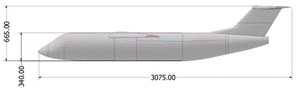
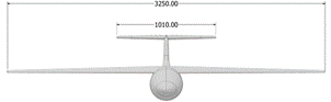
Fig. 3. UAV design in different views
(dimensions in mm)
3.1.7. Aerodynamic polar curves
The polar curve, showing the
relationship between ![]() and
and ![]() , was
constructed as seen in Figure 4 (
, was
constructed as seen in Figure 4 (![]() = 0.08). It can be observed in Figure 4 that
as lift increases, aerodynamic drag also rises. However, the drag remains
relatively low due to the wing’s design characteristics, which contribute to
improved stability. Subsequently, Figure 5 presents the relationship between
= 0.08). It can be observed in Figure 4 that
as lift increases, aerodynamic drag also rises. However, the drag remains
relatively low due to the wing’s design characteristics, which contribute to
improved stability. Subsequently, Figure 5 presents the relationship between ![]() and AoA, where
and AoA, where ![]() is 0.93 and
is 0.93 and ![]() = 20°.
= 20°.
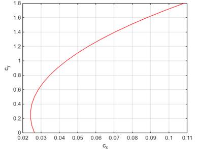
Fig. 4. Lift-drag polar curve
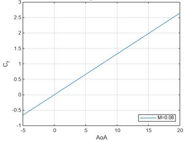
Fig. 5. ![]() vs AoA at
vs AoA at ![]() = 0.08
= 0.08
3.2. Fire extinguisher ball system design
The release system is integrated
within the UAV to prevent any alteration of its aerodynamic characteristics or
external shape during flight. The fire-extinguishing balls are discharged
sequentially, sliding down an internal inclined ramp that ensures their orderly
release.
3.2.1. Maximum take-off weight
As shown in Figure 6, the selected
UAV mission profile follows the operational role of a bomber aircraft,
consisting of nine segments as described in Table 1.
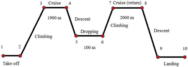
Fig. 6. Actual UAV mission profile
Considering ![]() = 1900 m (the hypothetical case on Figure 2),
= 1900 m (the hypothetical case on Figure 2), ![]() is 0.8 for a constant velocity propeller, and
is 0.8 for a constant velocity propeller, and ![]() is 0.068 mg/Ws. Under these conditions,
is 0.068 mg/Ws. Under these conditions, ![]() is 604.06 N and
is 604.06 N and ![]() is 429.97 kg. Based on this weight
distribution,
is 429.97 kg. Based on this weight
distribution, ![]() is 4.2255 kg.
is 4.2255 kg.
The fuel quantity in liters is
obtained using the density relationship. According to Zhao and Cui [26], Jet-A
fuel is optimal for medium UAVs equipped with piston engines, with a typical
density of 804 kg/m³. Therefore, the required fuel volume for this mission
is 5.25 L. For longer ranges, if ![]() = 10 km, the fuel requirement increases to
5.3738 kg, and for
= 10 km, the fuel requirement increases to
5.3738 kg, and for ![]() = 90 km, the maximum operative UAV weight
reaches 744.44 N.
= 90 km, the maximum operative UAV weight
reaches 744.44 N.
3.2.2. Volume of the fuel tank
![]() , within the
wings, is calculated as 23.8 L, corresponding to a maximum fuel weight of 19.14
kg. This fuel capacity allows estimating
, within the
wings, is calculated as 23.8 L, corresponding to a maximum fuel weight of 19.14
kg. This fuel capacity allows estimating ![]() = 750.27 N. When compared with the
= 750.27 N. When compared with the ![]() obtained in Section 3.2.1, the difference is
0.6305 kg, which represents an additional safety margin of 0.8% on top of the
initial 6% considered in equation (25).
obtained in Section 3.2.1, the difference is
0.6305 kg, which represents an additional safety margin of 0.8% on top of the
initial 6% considered in equation (25).
3.2.3. Engine position and cabin design
The design parameters calculated for
![]() ,
, ![]() and
and ![]() are 15, 244 and 314 mm, respectively.
are 15, 244 and 314 mm, respectively. ![]() = 1500 mm is considered, as shown in Figure 7.
Additionally, the slot designated for the release door is located beneath the
cabin, with dimensions of 400 mm × 200 mm.
= 1500 mm is considered, as shown in Figure 7.
Additionally, the slot designated for the release door is located beneath the
cabin, with dimensions of 400 mm × 200 mm.
3.2.4. Integrated system
Based on the suppliers listed in
Table 3, the Elide Fire extinguisher ball (152 mm diameter, 8-10 m²
effectiveness) was selected for this study (see Figure 8 for the integrated
system view). The proposed system consists of nine balls, providing a total
suppression coverage of approximately 90 m² and a payload weight of 13.5
kg. Accordingly, the UAV will be capable of carrying nine balls, each weighing
1.5 kg, achieving a fire suppression effectiveness of about 9 m² per ball
over a linear range of 90 meters.
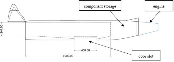
Fig. 7. Cabin geometry (dimensions in mm)
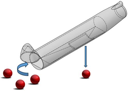
Fig. 8. Integrated fire extinguisher ball
system for UAV
Compared with traditional aerial
firefighting methods, such as water-dropping aircraft, fire-extinguishing balls
do not evaporate upon release and instead activate upon contact with flames,
providing localized chemical suppression at high-temperature ignition points.
Large aerial tankers can deliver substantially higher volumetric payloads;
however, their operability in remote areas is often limited due to the absence
of nearby water sources, which increases turnaround time per sortie.
Consequently, the operational cycle of large aircraft becomes extended,
particularly in regions such as the Peruvian rainforest, where long runways are
scarce.
In contrast, the proposed UAV is
intended to complement traditional methods by relying on pre-positioned
warehouses of fire-extinguishing balls located near high-risk wildfire areas.
Table 10 presents a comparison between the proposed UAV and large aerial
tankers under the hypothetical forest fire scenario illustrated in Figure 2 for
the Huicungo district, San Martín.
Tab.
10
Comparative
effectiveness of the proposed UAV and
a large aerial tanker under the Huicungo wildfire scenario
|
Parameter |
UAV (9 balls) |
Large aerial tanker |
|
Deployment time (remote areas) |
Low |
High |
|
Payload mass |
13.5 kg |
Several thousand kg |
|
Suppression precision |
High |
Moderate |
|
Operational frequency |
High |
Low |
|
Optimal deployment phase |
Early-stage / spot fires |
Fully developed fires |
3.3. CFD simulation
results
3.3.1. Domain
According to Wibowo et al. [27], the computational domain should be constructed using the aircraft length (3.075 m) as the reference parameter. Figure 9 illustrates the recommended domain dimensions.
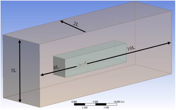
Fig. 9. Computational domain
3.3.2. Meshing
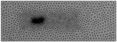
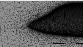
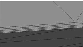
A mesh independence study was
conducted to determine the optimal mesh density for the simulations. Table 11
presents the results obtained at AoA = 0°, focusing on the estimation of ![]() . The
results of the mesh independence study indicated that the medium mesh
configuration (6’300 000 cells) was the most suitable for this case, with an
average element quality of 0.87 and an error percentage of 5.06% (see Table
11). Local refinements were applied, particularly around the UAV wings and
stabilizers (see Figure 10). Therefore, the next aerodynamic simulations at AoA
of 0°, 5°, 10°, 15° and 20° were performed using the Medium mesh. Note that Cai
et al. [28] recommend using more than 8 million elements for reliable CFD
analysis.
. The
results of the mesh independence study indicated that the medium mesh
configuration (6’300 000 cells) was the most suitable for this case, with an
average element quality of 0.87 and an error percentage of 5.06% (see Table
11). Local refinements were applied, particularly around the UAV wings and
stabilizers (see Figure 10). Therefore, the next aerodynamic simulations at AoA
of 0°, 5°, 10°, 15° and 20° were performed using the Medium mesh. Note that Cai
et al. [28] recommend using more than 8 million elements for reliable CFD
analysis.
Tab.
11
Results
of the mesh independence study
|
Mesh |
Cells |
|
Error |
|
Coarse |
3’200 000 |
0.0134 |
10.67% |
|
Medium |
6’300 000 |
0.0150 |
5.06% |
|
Fine |
13’200 000 |
0.0158 |
|
a)
b) c)
Fig. 10. Medium mesh views: a) general domain,
b) front of the UAV, and c) boundary layers
3.3.3. Boundary conditions
The velocity inlet was set at 30 m/s
(see Figure 11). An altitude of 100 m was considered; however, given that the
Peruvian Amazon ranges between 80 m and 400 m, an altitude reference of 500 m
was adopted. At this altitude, according to the Standard Atmosphere [29], air
density decreases from 1.225 kg/m³ at sea level to 1.167 kg/m³. The
air density value at 500 m was selected for the CFD simulations.
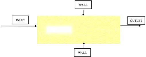
Fig. 11. Boundary conditions
3.3.4. Lift and drag forces
Table 12 presents the calculated
aerodynamic forces for AoA of 0°, 5°, 10°, 15° and 20°. As shown in Table 12,
the lift force (![]() ) increases
with AoA, while drag (
) increases
with AoA, while drag (![]() ) also
increases but to a lesser extent. Considering
) also
increases but to a lesser extent. Considering ![]() for
for ![]() = 1.9 km, the UAV must generate more than
604.06 N of lift to take off and maintain cruise flight. This condition is
reached at approximately 5°-10° AoA, defining the required operational AoA
under normal conditions. Although
= 1.9 km, the UAV must generate more than
604.06 N of lift to take off and maintain cruise flight. This condition is
reached at approximately 5°-10° AoA, defining the required operational AoA
under normal conditions. Although ![]() reaches 29.17 at 5°, the generated lift is
only 599.09 N, which is insufficient. Therefore, as suggested by Anderson [30],
interpolation between 5°-10° is required since the curve in this range is
approximately linear. Accordingly, for
reaches 29.17 at 5°, the generated lift is
only 599.09 N, which is insufficient. Therefore, as suggested by Anderson [30],
interpolation between 5°-10° is required since the curve in this range is
approximately linear. Accordingly, for ![]() = 10 km (
= 10 km (![]() = 615.32 N), the optimal AoA is 5.29°, while
for
= 615.32 N), the optimal AoA is 5.29°, while
for ![]() = 90 km the corresponding AoA is 7.73°.
= 90 km the corresponding AoA is 7.73°.
Tab.
12
Aerodynamic
forces at different AoAs
|
AoA |
|
|
|
|
0° |
291.800 |
16.634 |
17.542 |
|
5° |
599.078 |
20.541 |
29.165 |
|
10° |
875.720 |
93.382 |
9.378 |
|
15° |
1033.378 |
177.294 |
5.828 |
|
20° |
1012.838 |
207.498 |
4.881 |
![]() for the maximum operative UAV weight was
calculated as 66.53 kgf/m², which according to Raymer [13] indicates a
relatively short take-off distance, a favorable result for UAV operations in
remote and hard-to-access areas. For landing conditions,
for the maximum operative UAV weight was
calculated as 66.53 kgf/m², which according to Raymer [13] indicates a
relatively short take-off distance, a favorable result for UAV operations in
remote and hard-to-access areas. For landing conditions, ![]() was determined as 65.03 kgf, giving
was determined as 65.03 kgf, giving ![]() = 554.54 N/m².
= 554.54 N/m². ![]() was calculated using
was calculated using ![]() = 1.4 for the NACA 6412 airfoil [24] and
= 1.4 for the NACA 6412 airfoil [24] and ![]() = 0.4 from Raymer [13], yielding
= 0.4 from Raymer [13], yielding ![]() = 28.13. Based on this, the take-off distance
is 214.34 m, while the distance to clear a 50 ft obstacle is 317.23 m. For
landing,
= 28.13. Based on this, the take-off distance
is 214.34 m, while the distance to clear a 50 ft obstacle is 317.23 m. For
landing, ![]() was estimated using the obstacle clearance
requirement for UAVs of 50 ft, giving
was estimated using the obstacle clearance
requirement for UAVs of 50 ft, giving ![]() = 1040.77 ft, adjusted to the relative air
density at 400 m (Huicungo, San Martín). Finally, the thrust required for level
flight was determined using
= 1040.77 ft, adjusted to the relative air
density at 400 m (Huicungo, San Martín). Finally, the thrust required for level
flight was determined using ![]() . For the
maximum operative UAV weight, the required thrust is 300.11 N.
. For the
maximum operative UAV weight, the required thrust is 300.11 N.
3.3.5. Pressure and velocity contours
Pressure contours demonstrated a
proportional increase with AoA (see Figure 12). The results show that pressure
reaches its maximum values on the intrados, with the magnitude of pressure
rising as AoA increases. At 15°, a significant intensification of pressure
distribution is observed, while Table 12 indicates ![]() decreases between 15° and 20°. Furthermore, at
20° the lift shows a marked reduction, which can be interpreted as the onset of
stall. According to Belligoli et al. [31], an effective approach to reduce drag
in UAV design is the addition of fairings at the wing-fuselage intersection.
decreases between 15° and 20°. Furthermore, at
20° the lift shows a marked reduction, which can be interpreted as the onset of
stall. According to Belligoli et al. [31], an effective approach to reduce drag
in UAV design is the addition of fairings at the wing-fuselage intersection.
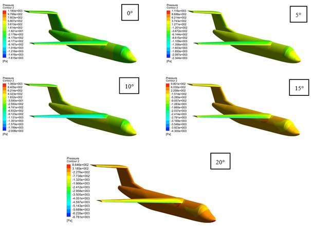
Fig. 12. Pressure contours on the UAV’s surface
at different AoAs
Velocity contours were obtained at
AoA = 0°, 5°, 10°, 15°, and 20° in the midsection of the UAV wing. At AoA = 0°,
Figure 13 shows the highest velocity values on the extrados, reaching 40.27 m/s
near the mid-chord of the profile. Compared with the other AoA cases, the 0°
simulation exhibits the highest overall velocity distribution. This behavior is
explained by the fact that increasing AoA leads to a general reduction of
velocity magnitude across the wing profile. At AoA = 15°, the highest velocity
is concentrated near the wingtip, caused by the limited space available for
airflow to reach the trailing edge due to wing inclination. Finally, at AoA =
20°, Figure 13 reveals a marked reduction in velocity along the trailing
section of the profile, evidencing airflow disproportion and the generation of
vortical trails.
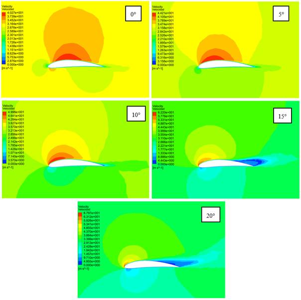
Fig. 13. Velocity contours around the wing’s
mid-span at different AoAs
4. CONCLUSION
The present work conceptually
designs a UAV for firefighting applications equipped with a fire-extinguisher
ball release system. The aerodynamic parameters were calculated using the NACA
6412 airfoil, resulting in a UAV with a length of 3.075 m and a wingspan of
3.25 m. A high-wing configuration was selected due to its superior
stability compared to mid- and low-wing designs, while a T-tail was chosen to
minimize airflow interference. The aerodynamic polar curve was obtained,
showing an increase of ![]() with
with ![]() .
.
The fire-extinguisher ball system
was designed to allow the UAV to carry 13.5 kg (9 balls of 152 mm), achieving a
firefighting effectiveness of 9 m² over a linear range of 90 m. Three case
studies were conducted to assess UAV range efficiency: for a range of 3.9 km,
the ![]() was calculated as 61.60 kg with an empty UAV
weight of 43.87 kg. For a maximum range of 180.01 km with 23.9 L of fuel, the
operative
was calculated as 61.60 kg with an empty UAV
weight of 43.87 kg. For a maximum range of 180.01 km with 23.9 L of fuel, the
operative ![]() reached 76.51 kg.
reached 76.51 kg.
CFD simulations at 500 m altitude
and 30 m/s airspeed were performed. The simulations provided lift and drag data
for AoA values of 0°, 5°, 10°, 15° and 20°. Results indicated that the optimal
AoA for operating under the first case ![]() is 5.09°, while the maximum operative
is 5.09°, while the maximum operative ![]() requires an AoA of 7.73°, corresponding to a
lift force of 750.27 N. Pressure and velocity contours confirmed that the UAV
operates efficiently up to AoA = 10°; however, at AoA = 15°-20°, a significant
reduction in lift and an increase in drag occur, indicating stall onset.
requires an AoA of 7.73°, corresponding to a
lift force of 750.27 N. Pressure and velocity contours confirmed that the UAV
operates efficiently up to AoA = 10°; however, at AoA = 15°-20°, a significant
reduction in lift and an increase in drag occur, indicating stall onset.
Operating in Amazonian environments
presents several challenges. High temperatures (>35°C) and humidity levels
of 80%-100% may affect UAV electronic components. Future research should
therefore focus on selecting more suitable materials, such as carbon-fiber
composites. Furthermore, heavy rain could interrupt signal transmission, making
it essential to integrate higher-resolution cameras and more robust
communication systems.
References
1.
Defensoría del Pueblo. 2024. Informe de
supervisión en el marco de los incendios forestales 2024: impacto,
responsabilidad y vulneración de derechos fundamentales. [In Spanish: Supervisory Report in the Context
of the 2024 Forest Fires: Impact, Responsibility, and Violation of Fundamental
Rights]. Lima:
Biblioteca Nacional del Perú.
2.
Sevzinski D.T., I. Georgiev, H.P.
Panayotov, S.I. Penchev. 2019. „Effective use of a helicopter with a Bambi
bucket firefighting system in Bulgaria”. In:
IOP
Conference Series: Materials Science and Engineering 664 (1): 012005.
IOP Publishing.
3.
Sousa V.R., V. Gamboa. 2020. „Aerial
Forest fire detection and monitoring using a small UAV”. KnE Engineering
5 (6): 242-256. DOI: https://doi.org/10.18502/keg.v5i6.7038.
4.
Wu R.Y., X.C. Xie, Y.J. Zheng. 2024.
„Firefighting Drone Configuration and Scheduling for Wildfire Based on Loss
Estimation and Minimization”. Drones 8 (1): 17. DOI:
https://doi.org/10.3390/drones8010017.
5.
Kau D., M.F. Evliyaoglu, S. Karakus, R.
Mörsch, L. Babetto, E. Stumpf. 2022. „DLR design challenge 2022: Next
generation firefighting aircraft – FireWASP”. In:
German
Aerospace Congress, Dresden, Germany: 27-29.
6.
Sharma L. 2024. „Involvement of drone
technology and fire extinguishing balls in firefighting”. Theory and
Practice 30(5): 2317-2326. DOI: 10.53555/kuey.v30i5.3282.
7.
Pawar M.R., B.K. Patle, N. Pagar. 2023.
„Design and Development of Fire Fighting Drone”. International Research
Journal of Innovations in Engineering & Technology 7(12): 249-258.
8.
De Moura J.P.A.S. 2021. „Autonomous
Targeting System for a Firefighting Drone”. Master’s thesis, Portugal:
Universidade de Coimbra.
9.
Dieteren S.H.P. 2021. „Application of
drone technology for firefighting”. Master’s thesis, Netherlands: University of
Twente.
10.
Aydin B., E. Selvi, J. Tao, M.J. Starek.
2019. „Use of Fire Extinguishing Balls for a Conceptual System of Drone
Assisted Wildfire Fighting”. Drones 3 (1): 17. DOI:
https://doi.org/10.3390/drones3010017.
11.
Artamonova L.G., A.V. Kuznetsov, N.N.
Pesotskaya. 2010. Verification Calculation of Aerodynamic Characteristics of
the Aircraft. Moscow: Moscow Aviation Institute.
12.
Aliaga Nestares V., N. Quispe Gutiérrez,
I. Ramos Parado, D. Rodríguez Zimmermann. 2018. Estudio de condiciones
atmosféricas favorables a los incendios forestales en el Perú. [In Spanish: Study of Atmospheric Conditions
Favorable to Forest Fires in Peru]. Lima: Servicio Nacional de
Meteorología e Hidrología del Perú.
13.
Raymer D.P. 2012. Aircraft Design: A
Conceptual Approach. Reston, VA: American Institute of Aeronautics and
Astronautics.
14.
Kennedy G., J.R. Martins. 2012. „A
Comparison of Metallic and Composite Aircraft Wings Using Aerostructural Design
Optimization”. In: 12th AIAA
Aviation Technology, Integration, and Operations (ATIO) Conference and 14th
AIAA/ISSMO Multidisciplinary Analysis and Optimization Conference: 5475.
15.
Jimenez D., E. Valencia, A. Herrera, E.
Cando, M. Pozo. 2025. „Evaluation of series and parallel hybrid propulsion
systems for UAVs implementing distributed propulsion architectures”. Drones
9(2): 63. DOI: https://doi.org/10.3390/aerospace9020063.
16.
Diogo C.M.A., E.C. Fernandes. 2024. „A
mass, fuel, and energy perspective on fixed-wing unmanned aerial vehicle
scaling”. Drones 8(8): 396. DOI: https://doi.org/10.3390/drones8080396.
17.
Torenbeek E. 1988. Synthesis of
Subsonic Airplane Design. London: Delft University Press.
18.
Chen C., X. Wang, W. Liu, Q. Li. 2023.
„Aerodynamic Simulation of a Cargo UAV with Twin-Boom and Rear-Mounted
Propeller”. In: Asia-Pacific International
Symposium on Aerospace Technology: 1490-1503.
Springer Nature, Singapore.
19.
Valmiki S., M. Chavan, S. Jolada, M.
Ladde, M. Mateen. 2024. „Fire Fighting Drone Using Fire Extinguisher Ball”. Journal
of Scientific Research and Technology 2(7): 27-36. DOI: https://doi.org/10.61808/jsrt117.
20.
NASA. „Navier-Stokes Equations”. Available
at: https://www.grc.nasa.gov/www/k-12/airplane/nseqs.html.
21.
Airforce Technology. „SIRTAP Tactical
Unmanned Aerial System (UAS), Spain”. Available at:
https://www.airforce-technology.com/projects/sirtap-tactical-unmanned-aerial-system-uas-spain/?cf-view.
22.
Aircrafts. „C919”. Available:
https://doc8643.com/aircraft/C919.
23.
Ramesh P.S., J.M.L. Jeyan. 2022.
„Comparative Analysis of Fixed-Wing, Rotary-Wing and Hybrid Mini Unmanned
Aircraft Systems (UAS) from the Applications Perspective”. INCAS Bulletin
14(1): 137-151.
24.
Dhakad A. S., A. Sawarni, G. Sahu, N. Sahu. 2015. „Analysis
of NACA 6412 Airfoil (Purpose: Propeller for Flying Bike)”. IOSR
Journal of Mechanical and Civil Engineering (IOSR JMCE) 12(1): 115-124. DOI: 10.9790/1684-1212115124.
25.
Wei Z., J.Li, S. Tang, Z. Yang. 2022.
„Investigation and Improvement of T Tail Junction Flow Separation for a
Demonstration Aircraft”. Aerospace 9(10): 567. DOI:
https://doi.org/10.3390/aerospace9100567.
26.
Zhao Z., H.Cui. 2022. „Numerical
investigation on combustion processes of an aircraft piston engine fueled with
aviation kerosene and gasoline”. Energy 239: 121848. DOI:
https://doi.org/10.1016/j.energy.2021.122264.
27.
Wibowo S.B., B. Basuki, S. Sutrisno, T.A.
Rohmat, S. Siswantoro, F. Nugroho, P. Ginting,
Z. Anwar. 2021. „Vortex Dynamics Study and Flow Visualization on Aircraft Model
with Different Canard Configurations”. Fluids 6(4): 144. DOI:
https://doi.org/10.3390/fluids6040144.
28.
Cai M., E. Abbasi, H. Arastoopour. 2013.
„Analysis of the performance of a wind turbine airfoil under heavy rain
conditions using a multiphase computational fluid dynamics approach”. Industrial
& Engineering Chemistry Research 52(9): 3266-3275. DOI:
https://doi.org/10.1021/ie300877t.
29.
ISO 2533:1975. Standard Atmosphere.
International Organization for Standardization.
30.
Anderson J.D. 2021. Fundamentals of
Aerodynamics. New York: McGraw-Hill.
31.
Belligoli Z., S. Guérin, B. Van
Oudheusden, R. Dwight. 2019. „Using an anti-fairing to reduce drag at wing/body
junctions”. AIAA Journal 57(4): 1468-1480. DOI:
https://doi.org/10.2514/1.J057481.
Received 06.12.2025; accepted in revised form 24.02.2026
![]()
Scientific Journal of Silesian
University of Technology. Series Transport is licensed under a Creative
Commons Attribution 4.0 International License