Article
citation information:
Chríbik, A., Luknár,
L. Combustion characteristics of high-energy syngas in internal combustion
engines under constant CO2 and N2 conditions. Scientific Journal of Silesian University of
Technology. Series Transport. 2026, 130,
65-76. ISSN: 0209-3324. DOI: https://doi.org/10.20858/sjsutst.2026.130.4
Andrej CHRÍBIK[1],
Lukáš LUKNÁR[2]
COMBUSTION
CHARACTERISTICS OF HIGH-ENERGY SYNGAS IN INTERNAL COMBUSTION ENGINES UNDER
CONSTANT CO2 AND N2 CONDITIONS
Summary. Within the framework of
promoting circular economy strategies and expanding the portfolio of renewable
energy sources, synthesis gases (syngas) produced from the gasification of
municipal and plastic waste constitute a promising alternative fuel. This research
investigates five high-energy syngas compositions, each maintaining constant
inert gas proportions (10% CO2 and 5% N2), focusing on
their combustion behavior in a spark-ignition
internal combustion engine designed for cogeneration applications. This analysis
focuses on the characterization of in-cylinder pressures, the indicated mean
effective pressure (IMEP), heat release dynamics, and the duration of the
combustion process. Experimental results demonstrate that elevated hydrogen
proportion in fuel mixtures accelerates combustion, evidenced by reduced burn
duration. However, hydrogen content did not exhibit a direct correlation with
peak in-cylinder pressure. The maximum peak pressure was achieved by a mixture
containing moderate hydrogen and elevated carbon monoxide content. A
hydrogen-rich mixture displayed the shortest burn duration yet produced the
lowest maximum pressure, attributed to spark timing positioned near top dead center (TDC). Methane concentration directly influenced the
volumetric lower heating value (LHV), subsequently affecting both IMEP and
torque output. Relative to methane operation, engine torque output decreased by
6% to 13.4%, while hourly fuel consumption increased from 1.55 kg.h-1
to 3.88 kg.h-1 depending on mixture composition.
Keywords: syngas from wastes, internal combustion engine, renewable energy from
waste
1. RESEARCH
CONTEXT
The advancement of sustainable energy
technologies has catalyzed significant research in
thermochemical waste conversion methods, particularly within circular economy
frameworks. Market projections indicate that the waste-to-energy sector was
valued at USD 42.5 billion in 2024, with anticipated growth to USD 68.0 billion
by 2030, representing a compound annual growth rate of 8.3% [1]. This expansion
reflects the convergence of rising energy demand, increasingly restrictive
environmental legislation, and alignment with United Nations Sustainable
Development Goals targeting carbon neutrality [2].
Municipal solid waste (MSW) generation exhibits
a persistent upward trajectory globally, with forecasts suggesting an increase
to 3.4 billion metric tons annually by 2050 [3]. Data from the central European
region demonstrate particularly pronounced growth trends, with per capita waste
production in the Slovak Republic, the Czech Republic, Hungary, the Republic of
Poland and Republic of Austria showing consistent increases over three decades
[4].
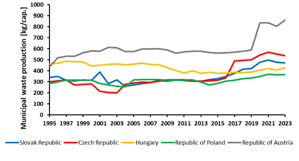
Fig. 1. Per
capita municipal waste generation trends in Central Europe [4]
Conventional waste management methodologies,
predominantly landfilling and direct thermal treatment, prove increasingly
inadequate due to environmental burden and limited resource valorization
potential [5]. Among advanced thermochemical conversion technologies,
gasification processes have demonstrated superior potential for MSW treatment.
This technology operates through controlled partial oxidation at elevated
temperatures with sub-stoichiometric oxygen supply, yielding synthesis gas – a
combustible gaseous mixture containing methane (CH4), hydrogen (H2),
carbon monoxide (CO), with inevitable inert components including carbon dioxide
(CO2) and nitrogen (N2) [6, 7]. Contemporary
technological developments in gasification systems, including enhanced updraft
reactor configurations and plasma-assisted gasification, have achieved improved
energy recovery efficiencies while minimizing pollutant emissions relative to
conventional combustion approaches [8, 9].
Utilization of synthesis gases in spark-ignition
internal combustion engines (ICE) for combined heat and power (CHP)
applications represents a technically viable pathway for distributed energy
generation, particularly in small to medium-scale installations. Experimental
investigations have confirmed that syngas-fueled ICEs
can achieve performance characteristics comparable to natural gas operation
while simultaneously contributing to waste volume reduction and fossil fuel
displacement [10, 11]. Nevertheless, compositional variability of waste-derived
syngas, influenced by feedstock heterogeneity and gasification operational
parameters, presents significant challenges for engine calibration and
operational stability [12, 13].
The physicochemical characteristics of syngas
deviate substantially from conventional gaseous fuels. Hydrogen content
enhances flame propagation kinetics and extends flammability limits,
facilitating lean combustion strategies with potential thermal efficiency
improvements [14, 15]. Conversely, carbon monoxide presence and inert gas
dilution affect volumetric lower heating value (LHV), consequently influencing
engine power output and specific fuel consumption [16]. A comprehensive
understanding of specific syngas compositional effects on combustion behavior, particularly under conditions representative of
waste-derived gases with standardized inert content, remains essential for
gasification-engine integrated system optimization.
Contemporary systematic reviews emphasize the
necessity for detailed investigation of syngas combustion characteristics in
ICEs, highlighting knowledge gaps regarding constant inert gas content
influence on engine performance parameters [17, 18]. While substantial research
has examined syngas utilization in dual-fuel configurations across various H2/CO
ratios, systematic analysis of fixed CO2 and N2
proportions across different H2, CO, and CH4 combinations
remains limited – a scenario particularly relevant to controlled gasification
processes targeting specific inert gas concentrations for operational stability
[19, 20].
This experimental investigation addresses this
research gap through examination of five distinct high-energy syngas
compositions, each formulated with constant carbon dioxide (10% vol.) and
nitrogen (5% vol.) proportions, representative of typical waste gasification
outputs following preliminary cleaning processes. The research focuses on a
spark-ignition internal combustion engine operating at rated speed conditions
appropriate for cogeneration applications. Key combustion parameters, including
in-cylinder pressure evolution, indicated mean effective pressure (IMEP), heat
release characteristics, and combustion duration, are systematically analyzed to elucidate the influence of varying H2,
CO, and CH4 content on engine operational behavior.
Research outcomes provide practical guidance for
configuring waste gasification technologies to achieve optimal syngas
composition for ICE-based CHP systems, thereby contributing to development of
economically viable and environmentally sustainable waste-to-energy solutions.
The present investigation
explores the operational impact of specific gaseous fuel mixtures on a
reciprocating internal combustion engine. The chosen fuels simulate syngas
compositions generated through municipal waste and plastic gasification,
thereby supporting the determination of favorable compositional limits for
syngas use. Table 1 provides the relevant fuel characteristics, and Figure 2
graphically displays their compositional profiles.
Tab. 1
Fundamental properties of the selected syngas
mixtures
|
Parameter |
Unit |
Methane |
SG1 |
SG2 |
SG3 |
SG4 |
SG5 |
|
N2 |
[% vol.] |
0 |
5 |
5 |
5 |
5 |
5 |
|
CO2 |
[% vol.] |
0 |
10 |
10 |
10 |
10 |
10 |
|
CO |
[% vol.] |
0 |
25 |
35 |
35 |
25 |
30 |
|
H2 |
[% vol.] |
0 |
40 |
30 |
10 |
30 |
20 |
|
CH4 |
[% vol.] |
100 |
20 |
20 |
40 |
30 |
35 |
|
Lower
heating value |
[MJ.kg-1] |
50.011 |
19.495 |
17.095 |
19.988 |
21.074 |
20.474 |
|
LHVmixture |
[MJ.kg-1] |
2.762 |
2.817 |
2.789 |
2.726 |
2.772 |
2.743 |
|
Lower
heating value |
[MJ.m-3] |
33.354 |
13.631 |
13.799 |
18.467 |
15.964 |
17.213 |
|
LHVmixture |
[MJ.m-3] |
3.172 |
3.064 |
3.100 |
3.145 |
3.090 |
3.115 |
|
Molar mass |
[kg.kmol-1] |
16.0 |
16.8 |
19.4 |
22.2 |
18.2 |
20.2 |
|
rNTP_ fuel |
[kg.m-3] |
0.667 |
0.699 |
0807 |
0.924 |
0.758 |
0.841 |
|
Mixture
composition |
[kg.kg-1] |
17.1 |
5.9 |
5.1 |
6.3 |
6.6 |
6.5 |
|
Fuel in air |
[% vol.] |
9.5 |
22.5 |
22.5 |
17.0 |
19.4 |
18.1 |
|
rNTP_mixture |
[kg.m-3] |
1.152 |
1.091 |
1.115 |
1.157 |
1.118 |
1.139 |
*LHV – lower heating value, NTP – normal temperature and
pressure
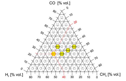
Fig. 2.
Ternary diagram of selected syngas compositions with constant inert gas
quantities (10% vol. CO2, 5% vol. N2), highlighting
example syngas SG1 composition (20% vol. CH4, 40% vol. H2,
25% vol. CO)
2. Experimental
Methodology
The
effects of the selected gaseous fuels on the combustion characteristics were
thoroughly investigated using a four-stroke, spark-ignition engine operating at
atmospheric conditions, specifically the Lombardini LGW 702 model. This
two-cylinder engine has a total displacement of 686 cm³, a compression
ratio of 12.5:1, and a crankshaft with a 180° phase separation. The air–fuel
mixture was generated using a mixing unit equipped with a diffuser, and the
mixture’s equivalence ratio was accurately regulated through a wideband lambda
sensor integrated within a closed-loop control system. A schematic
representation of the experimental engine setup is provided in Figure 3.
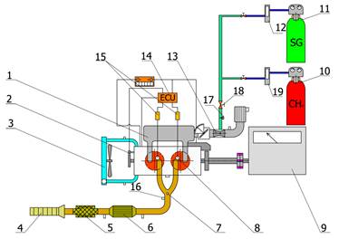
Fig. 3.
Schematic depiction of the LGW 702 engine, illustrating the arrangement and
identification of its principal components. (1 - Air intake manifold, 2 -
Engine crank angle sensor, 3 - Coolant radiator, 4 - Exhaust manifold, 5 - Muffler, 6 -
Three-way catalytic converter, 7 - Exhaust gas monitoring sensor for
temperature and pressure, 8 - In-cylinder pressure sensor integrated into spark
plug, 9 - Engine dynamometer (inductive type), 10 - Compressed methane cylinder,
11 - Compressed syngas cylinder, 12, 19 - Mass flow meters for gases, 13 -
Fuel-air mixing device with integrated diffuser, 14 - Electronic control unit
(ECU), 15 - Spark ignition coil, 16 - Wideband oxygen sensor, 17 - Incremental
rotary motor,18 - System for regulating air-fuel mixture)
For
this study, the selected engine served as the prime mover for a compact
cogeneration system. Consequently, the investigation concentrated on the
engine’s rated speed of
1 500 min-1. At this operating point, the spark ignition timing was
systematically varied to identify the optimal advance angle under
stoichiometric conditions at full load for each tested gaseous fuel. The
optimization of the advanced ignition angle was performed with the aim of
achieving the maximum indicated mean effective pressure during stable engine
operation. The analysis focused primarily on key combustion characteristics,
including in-cylinder pressure evolution, indicated mean effective pressure
(IMEP), and the fuel mass fraction burned (MFB). These parameters were obtained
from in-cylinder pressure measurements recorded using a Kistler spark plug
featuring an embedded pressure sensor. Data processing was carried out using a
custom-developed Matlab tool, which applies a
single-zone, zero-dimensional thermodynamic model founded on the first law of
thermodynamics for a closed system. The heat release rate was evaluated
employing the Rassweiler-Withrow method to accurately
characterize combustion dynamics. It should be noted that all experiments were
conducted at a single operating point corresponding to rated engine speed (1500
min-¹), full load, and stoichiometric air–fuel ratio. This
approach was intentionally selected to represent the typical steady-state
operation of small-scale cogeneration units. However, such a limitation restricts
the general applicability of the findings to other engine operating regimes,
such as part-load conditions, lean-burn strategies, or variable speed
operation. Combustion behavior, pressure development,
and IMEP trends may differ under those conditions due to changes in turbulence
intensity, residual gas fraction, and heat transfer characteristics. Therefore,
the presented results should be interpreted primarily within the context of
rated steady-state operation.
Furthermore,
the ignition timing was individually optimized for each tested fuel in order to
achieve maximum IMEP under stable operating conditions. While this procedure
ensures thermodynamically optimal combustion phasing for each mixture, it
partially influences the direct comparability of peak pressure levels and
pressure rise rates between fuels. Differences in combustion phasing may
therefore reflect both intrinsic fuel reactivity and the adjusted spark timing
strategy.
3. RESULTS AND DISCUSSION
The
combustion process was evaluated using in-cylinder pressure analysis. As
illustrated in Figure 4, the curves depict the averaged in-cylinder pressures
obtained from 195 consecutive engine cycles for each tested gaseous fuel,
operating under stoichiometric mixture conditions, optimal ignition timing,
full load, and an engine speed of 1500 min-¹.
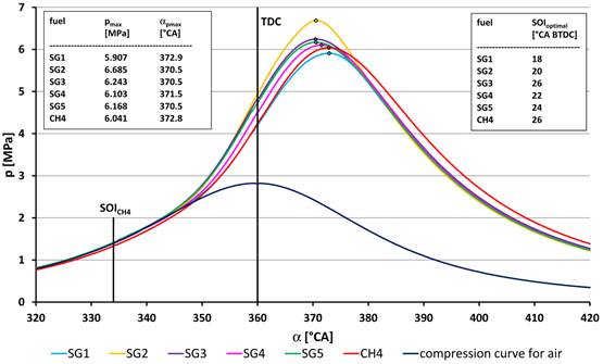
Fig. 4.
In-cylinder pressure development during combustion. Experimental conditions:
engine speed 1500 min-1, stoichiometric air–fuel ratio, full load,
and optimal ignition timing for each type of fuel
Because
the ignition timing was optimized individually for each gaseous mixture, the
observed differences in peak pressure position and magnitude cannot be
attributed solely to compositional effects. Instead, they represent a combined
outcome of fuel chemical kinetics and adjusted combustion phasing. This aspect
is particularly relevant when comparing hydrogen-rich mixtures, where faster
flame propagation required spark timing closer to TDC to prevent excessive
pressure rise during the compression stroke. As shown in Figure 4, the syngas labeled SG2 reached the highest peak pressure during
combustion, approximately 6.7 MPa, occurring near top dead center
(TDC) at 10.5° crank angle (CA) after TDC. This is primarily attributed to
SG2’s shortest combustion duration (α10–90MFB) among all
tested gases, as shown in Figure 5 below. In contrast, the lowest peak pressure
was observed with SG1 syngas, around 5.9 MPa, at 12.9°CA after TDC.
Interestingly, this phenomenon cannot be explained by variations in the
combustion period, as the combustion duration of SG1 was similar to that of
SG2, as shown in Figure 5. This finding is particularly notable considering SG1
contained the highest share of fast-burning hydrogen (40% vol.) among all syngases tested. Furthermore, the highest indicated mean
effective pressure (IMEP) was recorded for start of ignition (SOI) timings at
16°CA and 18°CA before TDC, closer to TDC than for any other syngas, which
likely influenced both the relatively low peak pressure and its delayed timing.
Other syngases produced only slightly higher maximum
combustion pressures compared to methane (ranging from 6.10 to 6.24 MPa versus
6.04 MPa), with peak pressures occurring marginally closer to TDC
(10.5°-11.5°CA after TDC versus 12.8°CA after TDC for CH4).
The
peak rates of pressure increase for most of the tested fuels were slightly
higher than those observed for the reference fuel, methane (0.225 MPa/°CA),
ranging from 0.230 MPa/°CA for SG2 up to 0.240 MPa/°CA for SG3. The only
exception was SG1, which reached only 0.195 MPa/°CA. This result is
somewhat surprising, as the fuel with the highest hydrogen content exhibited
the lowest pressure rise rate, while the fuel with the lowest hydrogen fraction
showed the highest rate.
The
combustion traces shown in Figure 5 reveal that each of the tested gaseous
mixtures exhibited faster burn rates compared to the stoichiometric methane
mixture, which reached a combustion duration of 24.4°CA. Among them, syngas SG3
exhibited the longest α10–90
MFB duration at 23.4°CA, while gases SG1 and SG2 shared
the shortest value of 19.5°CA. The slower combustion of SG3 was anticipated, as
its composition includes the lowest hydrogen content (10 vol.%) together with
the highest carbon monoxide (35 vol.%) and methane (40 vol.%) fractions.
Conversely, the mixture SG1, with the largest hydrogen fraction of 40 vol.%,
showed the shortest burn time, consistent with expectations.
Although
peak in-cylinder pressure and fuel burnout rates can indicate the effect of a
given fuel on brake torque, the Indicated Mean Effective Pressure represents a
more reliable metric for quantifying this influence. Figure 6 shows the IMEP
values for all tested fuels and ignition timings, with the data points
indicated by dots.
At
the optimal ignition timing, the highest mean IMEP was recorded for pure
methane, reaching 0.965 MPa, followed by syngas SG3 with an IMEP of 0.903 MPa.
The results in Figure 6 indicate that combustion of SG5 was associated with
significant IMEP fluctuations, suggesting potential instability in engine
operation. The coefficient of variation (COV) for SG5 at the optimal ignition
timing was 2.91%, nearly six times higher than that of SG2 (0.55%) and almost
twice the second-highest value observed for SG1 (1.71%).
The
third-highest Indicated Mean Effective Pressure was observed for SG4 (0.868
MPa), with SG2 (0.865 MPa), SG1 (0.861 MPa), and SG5 (0.860 MPa) trailing in
close succession. Interestingly, although SG5 exhibited the lowest average
IMEP, it generated the third-highest output torque, surpassed only by methane
and SG3; however, its torque also displayed notable fluctuations. Compared to
the methane operation, the output torque decreased by 6% for SG3 and by up to
13.4% for SG1.
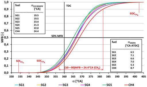
Fig. 5. Fuel
combustion progress as a function of crankshaft angle for methane and syngas
fuels (MFB - Mass Fraction Burned, α - Crankshaft Angle, SOC - Start of Combustion, SOI -
Start of Ignition, TDC - Top Dead Center, EOC - End
of Combustion); experimental conditions: engine speed 1500 min-1,
stoichiometric air-fuel ratio, full load, and optimal ignition timing for each
gas
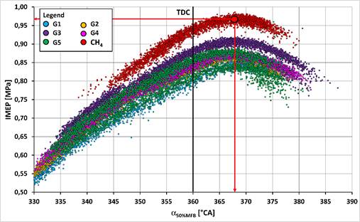
Fig.
6. Variation of the mean indicated effective pressure (IMEP) with crankshaft
angle at the point where 50% of the fuel mass has been burned (α50%MFB)
for methane and syngas fuels; experimental conditions: engine speed 1500 min-¹,
stoichiometric air-fuel mixture, full-load operation.
SG4
exhibited marginally higher performance parameters than SG2, reflected by an
IMEP of 0.868 MPa and an output torque of 39.5 N·m,
compared to 0.865 MPa and 38.7 N·m, respectively.
This is despite SG2 having a slightly greater volumetric lower heating value
(3.10 MJ·m-³ versus 3.09 MJ·m-³ for SG4).
The observed deviation can be attributed to variations in the methane-to-carbon
monoxide ratio between the two gaseous mixtures. When considered alongside the
data in Table 1, these results confirm the expected positive correlation between
the energy density per unit volume of a stoichiometric fuel mixture and the
resulting indicated mean effective pressure and brake torque.
Figure
7 presents how the maximum in-cylinder pressure varies with the crankshaft
position corresponding to 50% mass fraction burned (MFB 50%). The dataset was
acquired by progressively advancing the ignition timing from 40°CA before TDC
until reaching the operational stability limit of the engine. The adjustments
were performed in fine steps of 1°CA, and each point in the plot represents the
average of 197 successive cycles, ensuring statistical reliability.
For
the baseline fuel, pure methane, the analysis indicates that the peak pressure
plateaus at roughly 8.5 MPa. Once this threshold is reached, further ignition
advance yields no tangible pressure gain. This behavior
stems from the fact that, at excessive advance, the bulk of the combustion is
completed during the late compression stroke, before the piston attains top
dead center, meaning the trapped volume is still
shrinking. Consequently, the work potential of the expanding gases after TDC is
not significantly increased, even if peak pressure rises slightly earlier.
The
pressure, MFB 50% relationship forms a reverse S-shaped trend, with a clear
inflection at approximately 6.1 MPa and 8.5°CA after TDC. This point aligns
with the most favorable operating condition for
methane in this engine, corresponding to an ignition advance of about 26°CA
before TDC.
The
inverse S-curve behavior is characteristic of
spark-ignition engines approaching their optimal phasing, where the trade-off
between early combustion (which increases compression losses and knock
tendency) and late combustion (which reduces effective expansion work) reaches
a balance. The inflection point here is particularly important; it represents
the crank angle at which half the mixture has burned under conditions that
maximize both torque and efficiency. In practice, shifting MFB 50% closer to
TDC can improve thermal efficiency but risks unstable combustion or detonation,
while moving it too far after TDC sacrifices performance. The plateau in peak
pressure beyond optimal timing suggests that for methane, further advance
primarily increases negative work during compression, offering little benefit
to net indicated efficiency.
Due
to the 15% proportion of inert gases and the relatively low air-fuel ratio, a
rise in hourly fuel consumption was observed. The consumption increased from
1.56 kg·h-¹ for methane to 3.23 kg·h-¹ for SG4,
reaching a maximum of 3.87 kg·h-¹ for SG2. As expected, this
trend exhibited an inverse relationship with the air-fuel ratio.
4. CONCLUSION
The
utilization of waste-derived gases in cogeneration applications presents a
viable and environmentally advantageous alternative to conventional fossil
fuels. Their adoption not only contributes to landfill waste reduction but also
enhances the diversification of sustainable and low-carbon energy sources. When
used in internal combustion engines, these gases can deliver operational
characteristics comparable to those obtained with methane or natural gas.
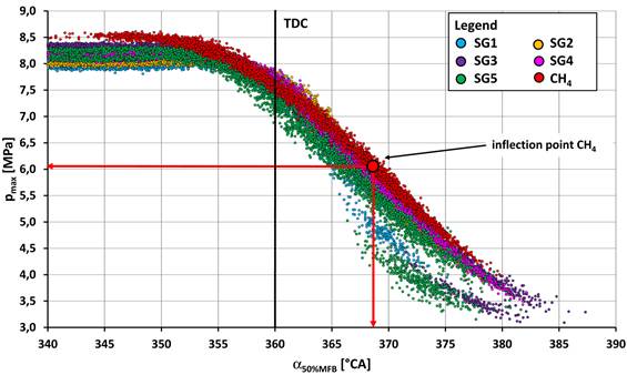
Fig. 7.
Variation of the peak in-cylinder pressure with crankshaft position at the 50%
mass fraction burned point for methane and syngas fuels (SG1-SG5). Experimental
conditions: 1500 min-1, stoichiometric air–fuel ratio, full
load
Parameters
such as peak in-cylinder pressure, its crank angle position, and the maximum
pressure rise rate exhibited only minor deviations from methane-fueled operation. The most pronounced differences were
observed in combustion duration and IMEP.
The
inclusion of hydrogen within the fuel blend promoted faster combustion and
shortened the overall burning period. However, due to the lower volumetric
lower heating values (LHVs) of the syngas mixtures, a modest decline in engine
torque was recorded. This reduction, accompanied by a slightly higher specific
fuel consumption, remained limited to approximately 6-13.4%.
The
principal effects resulting from variations in the gas mixture composition are
summarized below:
• Variations
in peak combustion pressure are primarily governed by the timing of the start
of ignition (SOI) rather than the hydrogen fraction alone. For mixtures with
higher hydrogen content, the SOI tends to shift closer to TDC, resulting in
comparatively lower peak in-cylinder pressures.
• Higher hydrogen fractions consistently
shortened the burn duration.
• Increased hydrogen content also lowered
the maximum rate of pressure rise.
• For
all mixtures except SG2 and SG4, the methane fraction primarily controlled the
mixture’s volumetric lower heating value at stoichiometry, exerting a direct
effect on both the indicated mean effective pressure and the engine’s torque
output.
• Hourly fuel consumption rose as the
air–fuel ratio decreased for all fuels.
• While
most fuels operated stably, SG5 exhibited notable IMEP fluctuations, indicating
potential operational instability.
• Comparing
SG2 and SG3 shows that a higher CO-to-CH4 ratio can accelerate
combustion and produce higher peak pressures, though it slightly reduces
overall engine performance.
It
must be emphasized that the conclusions drawn from this investigation are valid
for the examined steady-state operating regime only (1500 min-¹,
full load, stoichiometric mixture). Under part-load conditions or lean
combustion strategies, different relationships between hydrogen fraction,
combustion duration, and IMEP could be expected due to altered thermodynamic
and fluid-dynamic boundary conditions. Future research should therefore extend
the experimental matrix to variable speed and load regimes to provide a more
comprehensive characterization of high-energy syngas behavior
in internal combustion engines.
These
findings from the syngas evaluation can be applied in practical contexts,
providing guidance for configuring waste gasification processes to optimize
operational efficiency and enhance the economic performance of cogeneration
systems.
Acknowledgement
This research was supported by the
Slovak Research and Development Agency under Contract No. APVV-23-0456,
APVV-20-0046, and was also supported by the Scientific Grant Agency under
Contract No. VEGA 1/0666/24.
References
1. Grand View Research. Waste To
Energy Market Size, Share & Trends Report, 2030. Available at:
https://www.grandviewresearch.com/industry-analysis/waste-to-energy-technology-industry.
2. Karmakar A., T. Daftari, K. Sivagami, et al. 2023.
„A comprehensive insight into
Waste to Energy conversion strategies in India and its associated air pollution
hazard”. Environmental Technology & Innovation 29. No 103017. DOI: 10.1016/j.eti.2022.103017.
3. Pio D.T., L.A.C. Tarelho.
2022. “Waste Gasification Technologies: A Brief Overview”. Clean
Technologies 1(1): 11-35. DOI: 10.3390/cleantechnol4010002.
4. EUROSTAT. Municipal waste by waste
management operations. Available at:
https://ec.europa.eu/eurostat/databrowser/view/env_wasmun.
5. Yang M., L. Chen, J. Wang, et al. 2023. “Circular
economy strategies for combating climate change and other environmental issues”.
Environmental Chemistry Letters 21(1): 55-80. DOI:
10.1007/s10311-022-01497-3.
6. Vasileiadou A., L. Papadopoulou, et al. 2025.
“Advancements in waste-to-energy (WtE) combustion
technologies: A review of current trends and future developments”. Discover
Applied Sciences 7. No 457. DOI: 10.1007/s42452-025-06907-4.
7. Abedin T., J. Pasupuleti, J.K.S. Paw, et al.
2025. “From waste to worth: advances in energy recovery technologies for solid
waste management”. Clean Techn Environ Policy 27: 5963-5989. DOI: 10.1007/s10098-025-03204-x.
8. Nazari M., J. Haydary.
2024. “Gasification of municipal solid waste for power generation”. Journal
of Chemistry and Chemical Engineering 18(2): 45-58.
9. NETL. Gasifiers for Waste. Available
at:
https://www.netl.doe.gov/research/coal/energy-systems/gasification/gasifipedia/waste.
10. Suparmin P., R. Nurhasanah, L.O. Nelwan, et al. 2024.
“Syngas for Internal Combustion Engines, Current State, and Future Prospects: A
Systematic Review”. International Journal of Automotive and Mechanical
Engineering 21(4): 11857-11876. DOI: 10.15282/ijame.21.4.2024.05.0920.
11. Costa M., D. Piazzullo.
2024. “The Effects of Syngas Composition on Engine Thermal Balance in a Biomass
Powered CHP Unit: A 3D CFD Study”. Energies 17(3): 738. DOI: 10.3390/en17030738.
12. Fatiguso M., A.R.
Valenti, S. Ravelli. 2024. “Comparative energy performance analysis of micro
gas turbine and internal combustion engine in a cogeneration plant based on
biomass gasification”. Journal of Cleaner Production 434: 139782. DOI: 10.1016/j.jclepro.2023.139782.
13. Caligiuri C., M. Renzi, D. Antolini, et al. 2023.
„Optimizing the use of forestry biomass producer gas in dual fuel engines: A
novel emissions reduction strategy for a micro-CHP system”. Energy
Conversion and Management 20: 100498. DOI: 10.1016/j.ecmx.2023.100498.
14. Hagos F.Y., A.R.A. Aziz, S.A. Sulaiman. 2014. “Trends
of Syngas as a Fuel in Internal Combustion Engines”. Advances in Mechanical
Engineering 6. DOI: 10.1155/2014/401587.
15. Paykani A., et al. 2022.
“Synthesis gas as a fuel for internal combustion engines in transportation”. Progress
in Energy and Combustion Science 90: 100995. DOI: 10.1016/j.pecs.2021.100995.
16. Bonfanti N., P. Gaetani, G. Persico. 2020. “Internal
combustion engines powered by syngas: A review”. Energy Conversion and
Management 221: 113155. DOI: 10.1016/j.enconman.2020.113155.
17. Selvam D.C., Y. Devarajan, B. Nagappan, et al.
2025. “Sustainable fuel solutions: a comprehensive review of syngas in internal
combustion engines”. Chemical Papers 79(7): 4019-4027. DOI:
10.1007/s11696-025-04069-6.
18. Kohn M.P., M.L. Basinger, M.J. Castaldi. 2011.
“Performance of an Internal Combustion Engine Operating on Landfill Gas and the
Effect of Syngas Addition”. Industrial & Engineering Chemistry Research
50(6): 3570-3579. DOI: 10.1021/ie101937p.
19. Quintero-Coronel D.A., A. Salazar, O.R. Pupo-Roncallo, et al. 2023. “Assessment of the
interchangeability of coal-biomass syngas with natural gas for atmospheric
burners and high-pressure combustion applications”. Energy 276: 127551.
DOI: 10.1016/j.energy.2023.127551.
20. Kumar, A. 2023. “Experimental investigation of
a dual stage ignition biomass downdraft gasifier for deriving the engine
quality gas”. Ain Shams Engineering Journal 14(3): 101912. DOI:
10.1016/j.asej.2022.101912.
Received 28.10.2025; accepted in revised form 10.02.2026
![]()
Scientific Journal of Silesian
University of Technology. Series Transport is licensed under a Creative
Commons Attribution 4.0 International License