Article
citation information:
Tokarczyk,
J., Wójcicki, M., Wieczorek, A.N. Impact of load on the
contact surface of cooperating chain links of scraper conveyors. Scientific Journal of Silesian University of
Technology. Series Transport. 2025, 128,
283-294. ISSN: 0209-3324. DOI: https://doi.org/10.20858/sjsutst.2025.128.16
Jarosław TOKARCZYK[1], Mateusz WÓJCICKI[2], Andrzej Norbert WIECZOREK[3]
IMPACT OF LOAD ON
THE CONTACT SURFACE OF COOPERATING CHAIN LINKS OF SCRAPER CONVEYORS
Summary. The article presents
the impact of load on the contact surface of cooperating chain links in scraper
conveyors. A finite element method (FEM) simulation was conducted for a chain
operating on a sprocket, based on which stress and strain maps were determined
for different load levels. The contact surface areas of the chain links and the
reaction forces were also calculated depending on the load, which allowed the
determination of surface pressures.
Keywords: transport, link chain, FEM, scraper conveyor
1. INTRODUCTION
Chain
drives are one of the oldest and most widely used solutions in transport
technology, which have been a reliable system for transmitting power between
machine and equipment components. Their versatility, durability, and simplicity
of design make them an integral component of many transport devices, from
typical equipment such as bicycles or motorcycles to advanced conveyor units
used in the mining, cement, and power industries.
The
most commonly used conveyor solution based on a chain drive is the scraper
conveyors. Mining scraper conveyors are classified as cable conveyors, where
the cable is a chain/chains driven by a chain wheel and moving along the
conveyor chute. Scrapers installed transversely to the direction of movement of
the chain (installed at equal intervals - with a constant pitch) are the
transporting components. Chains with scrapers create a closed loop (endless
chain) consisting of two branches. A closed loop can be both horizontal and
vertical (more often) [1, 2, 9-11] .
Fig. 1.
Schematic design of the scraper conveyor – view on the upper part of a chain
(V – direction of the material/run-of-mine transport)
The
principle of operation of the scraper conveyor is to generate torque on the
chain wheel (through the drive – a motor and a gear) and transmit it in the
form of a pulling force to the chain links with the scrapers. Both the scraper
chain and the scrapers are located inside the conveyor pan, which creates a
transport channel shielded on three sides. Movement of the chain and sliding of
the scrapers along the conveyor pans result in the removal of the excavated
material and its transport along the chain movement to the end point of
transport or the next means of transportation [1, 2, 9-11].
Cooperation
of chain links with the drum, cooperation between the links in the joint area,
and the extremely difficult and complex environmental conditions in hard coal
mining plants result in the complexity of the wear processes of link chains in
terms of friction, corrosion, and fatigue. The most important factors
increasing the degradation of chains and scraper conveyor assemblies are the
following:
·
stone and
coal dust in the cooperation zone of chain links (joints),
·
corrosive
effect of mine water from the spraying devices and from goafs,
·
dynamic
loads from conveyor drive starts and uneven loads,
·
frequent
overloading and blocking [3, 4, 6, 8].
Analysis
of contact between neighboring chain links that
articulate with each other while rolling through the drive or return wheel is
important regarding the chain degradation process. These links have a point
elastic contact on the torus inside of each cell. Theoretical basis for the
analysis of such zones includes, among others, the Hertz problem, which is the
foundation of the state-of-the-art theory of elastic contact. Described by
the German physicist Heinrich Hertz in 1882, this problem concerns the analysis
of stresses and strains arising in elastic bodies at their points of contact.
Hertz's theory is extremely important for understanding how materials behave
under contact loads, which has wide applications in the design of mechanical
components such as bearings, gears, shafts, and many other components exposed
to point or linear contact [5].
The
basic assumption of Hertz's theory is the analysis of contact between two
elastic surfaces in a situation where they do not undergo plastic deformation.
In practice, this means that materials behave according to Hooke's law, and
deformations are proportional to the applied forces. The Hertz problem allows
determining the distribution of stresses and strains in the contact area, which
allows assessing the durability and strength of the analyzed
components. Precise calculations enable predicting the extent to which surfaces
will deform and determine the maximum stresses, which are crucial to avoid
damage and premature wear.
Nowadays,
Hertz's theory is the foundation for many advanced computational methods, such
as the finite element method (FEM), which enables more complex and precise
contact analyses. This article presents deformation analyzes
and surface pressure analyzes of cooperating chain
links using computer methods. The cooperating links have point contacts of the
two internal parts of the tori, which is consistent with the described issues.
The analysis required using the special software based on the finite element method.
Hexagon software was used, i.e., Patran pre- and post-processor and Nastran
computational solver. Nonlinear static analysis was performed. Nonlinearities
resulted from simulating the contact and use of an elastic-plastic material
model.
2. GEOMETRIC
MODEL
The
3D geometric model (Fig. 2) making the basis for creating the computational
model was designed using Autodesk Inventor software. It consists of a driving
star and one pair of links 14x50. The size of the actual conveyor chain was
selected according to PN-G-46701:1997 Standard - Mine link chains [7].
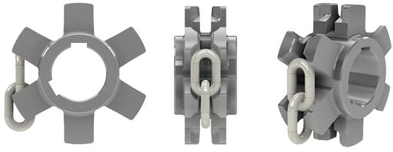
Fig. 2. 3D
geometric model of the driving star with a pair of cooperating links
3.
COMPUTATIONAL MODEL
3.1. Finite
elements mesh
The
geometric model was moved to the Patran preprocessor environment. This model
was then discretized and a finite element mesh was created, consisting of the
following:
·
533
thousand nodes,
·
69
thousand finite elements TET10 – driving star represented by a section that is
1/3 of the geometric model (Fig. 3). The TET10 element is a ten-node
tetrahedral element used in numerical simulations. It consists of 10 nodes: 4
at the vertices and 6 at the midpoints of the tetrahedron's edges. It enables
modeling of complex geometries and stress fields with greater accuracy than
simpler elements due to quadratic shape functions. It is applied in analyses of
mechanics, thermodynamics, or fluid flow.
·
40.4
thousand finite elements HEX8 – two chain links. The HEX8 element is an
eight-node hexahedral element used in numerical simulations. It consists of 8
nodes located at the vertices of a cube. It enables modeling of regular
geometries and physical fields with good accuracy, using linear shape
functions. It is applied in analyses of mechanics, thermodynamics, or fluid
flow, particularly in regular structures. HEX8 elements are more efficient
because with a smaller number of nodes, they enable obtaining results of higher
quality than TET10 elements, especially in non-linear tasks, i.e. contacts and
large deformations, (Fig. 4),
·
number of
HEX8 elements has been increased in the contact zone (Fig. 5).
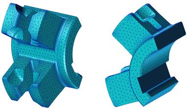
Fig. 3. Finite
elements mesh of a driving star (TET10 solid elements)
Fig. 4. Finite
elements mesh of collaborating links (HEX8 solid elements)
Fig. 5.
Increased number of finite elements in the contact zone between chain links
3.2. Finite
elements mesh
There
are the following assumptions and material parameters for numerical analysis:
·
driving
star – linear-elastic material:
Ø Young’s modulus – 205 GPa,
Ø Poisson’s number – 0.3,
·
chain
links – linear-elastic material with reinforcement C grade steel:
Ø Young’s modulus – 205 GPa,
Ø Poisson’s number – 0.3,
Ø conventional yield strength – 700 MPa,
Ø tensile strength – 850 MPa,
Ø relative elongation at a breaking load – 14%.
3.3. Boundary
conditions
For
the purposes of the calculations, the following boundary conditions were
assumed:
·
rotation
of the driving star around the axis of rotation, Fig. 6 - the rotation was
forced by a displacement corresponding to the relative elongation of the pair
of links at breaking load and was equal to 0.17 rad - a relative elongation of
14% corresponds to the elongation of the pair of links by 14 mm,
·
connection
of the drive star to the chain link - to force movement of the chain link
(upper link), in line with the moving drive star, MPC RBE2 type replacement
elements were used. MPC RBE2 (Multi-Point Constraint Rigid Body Element 2)
elements are a type of element used in numerical simulations, particularly in
finite element analysis (FEA). They are rigid elements that define a kinematic
relationship between one independent (master) node and one or more dependent
(slave) nodes. The motion of the independent node fully determines the motion
of the dependent nodes, with no relative displacement between them, imparting
infinite stiffness to the modeled region. RBE2 is used to represent rigid
connections, such as in modeling rigid structural components like beams or
welded joints, where deformation between nodes is negligible. Star nodes and
links are connected using these elements, Fig. 7,
·
contact
between the combined elements - spatial contact was used on the surface of the
links and the driving star, Fig. 8. Friction coefficient µ = 0.1 was
introduced,
·
fixation
of the lower link - to recreate cooperation of the link with subsequent links,
the MPC RBE2 substitute element was used to obtain support while simultaneously
monitoring the reaction value in one node, Fig. 8.
4.
DISPLACEMENT AND REDUCED STRESSES
The
simulation was carried out by generating the rotation of the driving star until
the chain links were extended by 14% - that is, until the moment that,
according to the catalogue, is the minimum at which the link breaks. All
published results of strength calculations use the SI system of units. Maps of
displacements and reduced stresses at 14% elongation are shown in Fig. 9-10.
Fig. 11 shows the change in the stress map for elongation of 0.7%, 1.4%, 3.5%,
7%, 10.5% and 14% (corresponding to 5, 10, 25, 50, 75 and 100% of maximum
elongation, respectively).
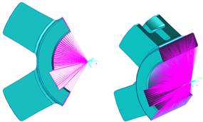
Fig. 6.
Rotation of the driving star around its axis of rotation. MPC RBE2
special numerical component
is used (purple color)
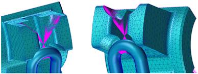
Fig. 7.
Connection of the link with a driving star. MPC RBE2
special numerical component is used to connect two separate components
Fig. 8.
Definition of contact on the surface of the links and the driving star (left),
fixation of the lower part of the link with the MPC RBE2 element (right)
Fig. 9. Map of
displacements (real deformation) on a dimensionless scale
Fig. 10. Map
of reduced stresses – on the left where red means a stress >700MPa,
and on the right >850MPa
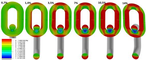
Fig. 11. Map
of reduced stresses on the longitudinal cross-section of links pair
– tension zones are marked with yellow and red and compression zones with green
and blue – displacement 0.7-14%
5. CONTACT
BETWEEN THE LINKS
Fig.
12 and 13 present the contact surfaces between the links for each degree of
their elongation (according to Fig. 11).
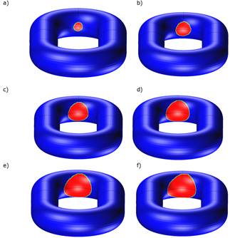
Fig. 12.
Contact surfaces between the links for each degree of their elongation:
0,7% (a), 1,4% (b), 3,5% (c), 7% (d), 10,5% (e) and 14% (f)
The
surface areas of each contact for each degree of elongation are shown in Fig.
13 below.
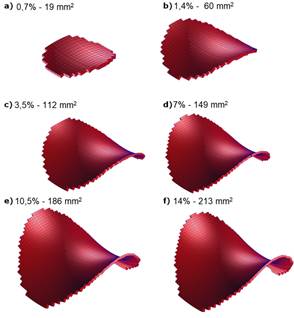
Fig. 13. Area
of contact surfaces between the links for different levels of link elongation
The
form of the deformation of the pair of links in the area of the contact zone
and the reaction value are shown in Fig. 14.
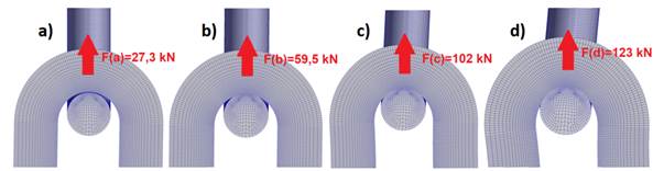
Fig. 14.
Deformation in the zone of links cooperation at the following links
elongations:
0.7% (a), 1,4% (b), 7% (c), and 14% (d)
Determining
the contact areas and the magnitude of the reaction allows for the estimation
of the surface pressures in the contact zone. These values are presented in the
Table 1 below.
Tab.
1
Determination of surface pressures
|
Link elongation |
Reaction [kN] |
Contact surface area [mm2] |
Surface pressure [MPa] |
|
0.7% |
27.3 |
19 |
1436 |
|
1.4% |
59.5 |
60 |
991 |
|
3.5% |
91.3 |
115 |
793 |
|
7% |
102 |
149 |
685 |
|
10.5% |
111 |
186 |
597 |
|
14% |
123 |
213 |
577 |
The
results regarding displacement maps, reduced stresses, main stresses,
identification of compression and tension zone,s and
the shape of the contact surface are presented for a chain link of real
dimensions and strength parameters in accordance with the PN-G-46701:1997
Standard.
Reaction
of 123 kN corresponds to the maximum link elongation
(14%) declared by the manufacturer for class C chain steel.
After
achieving the assumed elongation, the numerical simulation was stopped because
its further elongation may be a source of the following:
·
numerical
instabilities (increasing the error in the obtained results),
·
discrepancies
in the results obtained on the test stand (by the manufacturer), which are
related to the possibility of a random crack propagation (loss of material
continuity). This randomness is related to the manufacturing process of each
batch of links (e.g. the possibility of inclusions of contaminants inside the
material or its inhomogeneity).
6. CONCLUSIONS
The
results of the analysis described in this article, especially the determination
of the contact area of two links depending on the applied load (Fig. 12-13) and
the resulting surface pressures, allow forecasting the progress in chain wear.
As
expected, the contact area of chain links increases with elongation increase,
thus changing the point contact in the unloaded state with surface contact of
the loaded links. The growth rate of the links contact area decreases and is
the highest at the first stage of elongation and decreases with its increase.
Surface
pressure is the highest at the first stage of elongation and decreases as the
reaction increases below the yield stress value. Therefore, it can be concluded
that the cooperating loaded links adapt to each other at the first stage of
cooperation, creating the surface contact zone. Due to exceeding the yield
point, this zone does not return to the point contact state after the load is
removed.
This
analysis is part of broader research work related to the synergistic impact of
environmental factors on the wear of chain links depending on the combined
operating factors. In the presented work, the contact parameters of the
cooperating cells were determined for the needs of the mentioned research
work carried out using a dedicated test stand (description in [12]). These
guidelines enable determining the nominal parameters of the mentioned test
stand in terms of load and strength, in particular in the aspect of determining
the nominal force loading the chain links during tests, which will generate
degradation of the chain joint with the dominant tribological factor and
not as a result of decohesion or plastic deformations.
It
should be noted that there is a trend in which the frictional wear process in
cooperating parts is increasingly simulated using a coupling of two different
computational methods. As coal or rock are not continuous materials, they
are simulated in a software environment based on the Discrete Element Method
(DEM), in which it is possible to map the behavior of
these materials including simulating the wear process on the surfaces of the
wearing parts that are most exposed to loads. The deformations and stresses
that occur in metallic components, on the other hand, are calculated using the
finite element method [13, 14, 15]. This should be considered as a potential
direction for further research work.
The
obtained analysis results are of significant importance from the perspective of
broadly defined transport, particularly in the context of the operation and
design of scraper conveyor systems used in the mining, extraction, or energy
industries. Determining the contact parameters of interacting chain links and
understanding the relationship between load, contact area, and surface
pressures enables the optimization of chain design, enhancing their durability
and reliability. Precisely identifying the conditions under which the
transition from point contact to surface contact occurs facilitates better
prediction of tribological wear, which translates into reduced maintenance
costs and downtime for conveyors. Furthermore, these results support the design
of test rigs that reflect real operational conditions, which is crucial for
ensuring the safety and efficiency of bulk material transport in challenging
environmental conditions, such as mines or raw material processing plants.
References
1.
Antoniak Jerzy, Aleksander Lutyński. 2000. „Inteligentny system napędowy CST dla
ścianowych przenośników zgrzebłowych dużej mocy”. [In
Polish: “Intelligent CST drive system for high-power longwall scraper conveyors”].
Maszyny Górnicze
83. Publishing house: CMG KOMAG. ISSN: 0209-3693.
2.
Antoniak Jerzy, Józef Suchoń. 1983. Górnicze przenośniki zgrzebłowe. [In Polish: Mining
scraper conveyors]. Publishing house: Śląsk. ISBN:
8321603629.
3.
Celis Jean Pierre, Pierre Ponthiaux. 2011. Testing tribocorrosion
of passivating materials supporting research and industrial innovation.
European Federation Corrosion by Maney Publishing. ISBN: 978-1907975202.
4.
Dolipski Marian, Eryk Remiorz; Piotr Sobota. 2012. “Determination of dynamic loads of sprocket
drum teeth and seats by means of a mathematical model of the longwall conveyor”. Archives of Mining Sciences
57(4). ISSN: 0860-7001.
5.
Hertz Heinrich. 1982. “Ueber
die Berührung fester elastischer
Körper”. [In German: “On the Fixed Elastic Body Contact”]. Journal
für die Reine und Angewandte Mathematik
92. De Gruyter. ISBN: 978-3112342398.
6.
Mikuła Stanisław. 1978. Trwałość zmęczeniowa cięgien łańcuchowych górniczych maszyn
urabiających i transportowych. [In Polish: Fatigue life of
chains of mining and transport machines]. CMG KOMAG.
7.
PN-G-46701:1997 – Łańcuchy
ogniwowe górnicze. Warszawa: Polski Komitet Normalizacyjny.
[In Polish: Mining link chains. Warsaw: Polish
Committee of Standardization].
8.
Remiorz Eryk, Stanisław
Mikuła. 2017. „Podstawowe formy
degradacji własności użytkowych łańcuchów ogniwowych górniczych stosowanych w
maszynach ścianowych”. [In Polish: “Basic forms of
degradation of functional properties of mining link chains used in longwall
machines”]. Maszyny Górnicze
35(3). ITG KOMAG. ISSN: 2450-9442.
9.
Suchoń Józef. 2012. Górnicze
przenośniki zgrzebłowe: budowa i zastosowanie. [In Polish:
Mining scraper conveyors: construction and application]. ITG KOMAG. ISBN: 978-83-60708.
10.
Suchoń Józef. 2012. Górnicze
przenośniki zgrzebłowe: teoria, badania i eksploatacja. [In Polish:
Mining scraper conveyors: theory, research and operation]. ITG KOMAG.
ISBN 978-83-60708-69-9.
11.
Wieczorek Andrzej Norbert. 2018. Badania skojarzonego oddziaływania górniczych czynników środowiskowych
na degradację powierzchni bębnów chodnikowych przenośników zgrzebłowych. [In
Polish: Research on the combined impact of mining environmental factors on
the degradation of the surface of the roadway drums of scraper conveyors].
Publishing house of the Silesian University of Technology. ISBN:
978-83-7880-571-7.
12.
Wójcicki Mateusz, Andrzej Norbert Wieczorek, Grzegorz
Głuszek. 2021. “Concept
of the facility for testing the wear of chain links in the aspect of synergism
of environmental factors”. Mining Machines 39. ITG KOMAG. ISSN:
2719-3306. DOI: 10.32056/KOMAG2021.4.1.
13.
Xunan
Liu, Du Changqing, Fu Xin, Zhao Han, Zhang Jianzhuo, Yang Xinle. 2021. „Wear analysis and performance optimization of drum blade
in mining coal gangue with shearer”. Engineering
Failure Analysis 128. ISSN:
1350-6307. DOI: 10.1016/j.engfailanal.2021.105542.
14.
Yang Lu,
Hong Zhang, Ranhang Gao, Qian Feng. 2024. „Study on Contact Characteristics of Chain Track Interface
and Distribution Law of Coal Bulk Material of Short-distance Scraper Conveyor”. Mining, Metallurgy & Exploration 41. ISSN: 2524-3470. Available at: https://ui.adsabs.harvard.edu/link_gateway/2024MMExp.41.3257Y/doi:10.1007/s42461-024-01093-0.
15.
Yang
Xinwei, Dongxuan Wu, Hongyue Chen, Dong Wang. 2024. „Study on the force chain characteristics with coal dust
layer and the three-body contact stiffness”. Particuology 92. ISSN: 1674-2001. DOI: 10.1016/j.partic.2024.05.014.
Received 30.11.2024; accepted in revised form 05.03.2025
![]()
Scientific Journal of Silesian
University of Technology. Series Transport is licensed under a Creative
Commons Attribution 4.0 International License