Article
citation information:
Opasiak, T., Hełka,
A. Influence
of fastening method of wheeled armored vehicle on flat wagon for forces
transmitted by lashing elements. Scientific
Journal of Silesian University of Technology. Series Transport. 2025, 128, 163-181. ISSN: 0209-3324. DOI: https://doi.org/10.20858/sjsutst.2025.128.10
Tadeusz OPASIAK[1], Andrzej HEŁKA[2]
INFLUENCE OF
FASTENING METHOD OF WHEELED ARMORED VEHICLE ON FLAT WAGON FOR FORCES
TRANSMITTED BY LASHING ELEMENTS
Summary. During the
transportation of cargo on the type Slmmps wagon
platform, significant attention is paid to securing the transported load on a
given wagon platform, primarily based on the imposed loading instructions. In
the subject literature, there are no direct computational analyses on the
forces acting on a specific type of cargo with a given mass, particularly under
critical conditions. This article presents an analysis of the security of an armored vehicle in a platform wagon under critical
conditions. Securing analysis was conducted for two fastening methods: the
cross method (with a large strap angle relative to the direction of travel) and
the straight method (with a small strap angle relative to the direction of
travel). On the basis of these fastening methods, an assessment was made of the
security of the transported cargo in the form of an armored
vehicle. Armored vehicles are most commonly secured
using the cross-fastening method with four securing straps. This study compares
the force magnitudes concentrated on the securing straps in the cross-fastening
and straight-fastening methods.
Keywords: fastening, lashing capacity, armored
transporter
1. INTRODUCTION
The correct securement of the transported load
influences the safety of the transported cargo. It is a significant logistic
element in a transport chain. Properly secured loads do not cause interruptions
in the logistics chain caused by faulty cargo securing and do not threaten the
transport infrastructure. The nature of the threat depends on the type and form
of cargo transported, the means of transport, and the methods of securing the
cargo for the duration of the transport [2, 3, 10, 15, 16, 19, 22].
Military
operations units conduct various types of operational or training activities,
most often outside of their permanent accommodation. In such cases, it becomes
necessary to relocate units along with their combat equipment to the site of
military operations, either at a firing range or to an area designated for
operational use. Given the dimensions and quantity of military equipment, the
most advantageous and cost-effective method of such transport is by rail. In
railway transport, specific transportation procedures are applied, as regulated
by the appropriate normative documents [14, 27, 29].
A significant
advantage of using rail transport for military logistics is the availability of
the necessary rail platforms designed for the transport of armored vehicles.
One such platform is the Slmmps series platform,
which is capable of operating throughout Europe. The general parameters of the Slmmps series rail platform allow for the loading and
transportation of, among other things, armored vehicles equipped with tracks
and those fitted with rubber wheels. Each wagon of this type of platform has 6
axles, a maximum load capacity of 60 tons, a loading length of 10.94 meters, a
width of 3.09 meters, and a tare mass of 20 tons [29, 38].
Various
means of transport are used to transfer military personnel and military
equipment. For strategic transfer of armed forces, sea and air transport are
used, and for operational and tactical transport, primarily land transport.
Strategic transport occurs between seaports and airports. The delivery of
military forces and resources to the ports of embarkation and from the ports of
disembarkation to the areas of operational destination occurs primarily by land
transport, such as road or rail. The choice of means of transport depends on
the operational and economic criteria adopted. The most important include the
time of movement forces and the cost of the transport operation. High-mass
cargo transport irregularities and operational needs characterize military
loads. In particular, there is a need to maintain appropriate precautions in
preparation for transporting heavy loads of military technology. Depending on
the nature and purpose, military loads are divided into [23, 29]:
–
operational load – includes the transport of
soldiers with their equipment;
–
supply load – includes the transport of weapons,
military equipment, and combat means;
–
evacuation loads – related to the evacuation of
unnecessary equipment, damaged or inoperable equipment, and packaging.
The
choice of means of transport for military transport is one of the most
important strategic decisions. When planned, military transport should
primarily strive to achieve two goal functions: ensuring timely completion of
the task and an acceptable level of incurred costs. Rail transport can
transport large loads at speeds higher than the speed of trucks in road
transport, which means that rail transport has greater inertia forces [1, 5, 8,
9, 17, 18, 24, 26, 30]. Failure to adequately secure the transported load can
cause the destruction of the load itself, the rail infrastructure, and the
death of people in the immediate vicinity and other technical means. Due to the
specific nature of its construction, the transport of armored vehicle carriers
causes numerous difficulties. Starting from the plan of the transportation
organization, through the selection of the appropriate transport set, and
focusing on its proper securing through its proper lashing on the flat wagon.
Wheeled armored vehicles as a means of combat transport are characterized by
high combat mobility, which is why they are very often used in military
operations. On the other hand, on long railway routes, wagon platforms are used
for them. Due to the specificity of this type of freestanding load on the wagon
platform, they should be properly secured by general standards [4, 5]. An
appropriate securing method should be provided for this type of load to ensure
maximum safety during its movement. Therefore, in the present work,
recommendations and guidelines have been taken into account with respect to the
requirements imposed on railway transport contained in TSI-related regulations,
the EN 12663-2:2010 railway standards [5], and national instructions Ch-6 [25].
Military combat vehicles are delivered to combat areas by rail or road
transport, which is used in civilian transport. Armored vehicles are moved
using wagon platforms or semitrailers [15, 20, 26, 30]. The general legal
regulations in Poland regarding cargo securing are specified in the PN-EN 12195
standard, which is detailed with the principles defining cargo securing [4].
However, the requirements for securing military vehicles by rail transport are
included in the "Instruction on the carriage of soldiers by rail",
which provides examples of securing wheeled and tracked vehicles on rail wagons
[20, 29]. When conducting military transports using rail transport, a variety
of requirements must be met, stipulated by railway regulations and those that
take into account the specific nature of military needs [4, 5, 8, 14, 20, 29].
When securing the cargo on a flat wagon, the main forces acting on the armored
vehicle "Rosomak" are at work [14]. This is
the main guideline taken into account in the calculations according to the
PN-EN 12195 standard, which also describes the forces coming from the anchoring
elements used in various methods of securing cargo (including strapping,
anchoring, and blocking) [4, 5, 8]. During movement, the armored transporter is
mainly exposed to mechanical impact in the form of inertia forces, which are
the main forces that cause the transported load to slide off the flat wagon.
Due to the nature of the impact, these loads are the impact of dynamic forces,
mainly related to the change in the speed of the wagon itself and the change in
the direction of movement on the track arcs. Dynamic forces acting on the
armored transporter can be short-term in the form of an impact or quickly
changing in the form of vibrations. This sensitivity of the load to mechanical
impact can be minimized by appropriate immobilization using appropriate
fastening elements. For practical fastening, there are fastening elements in
the form of belt lashings, chain lashings, and various types of blocking
elements with nonslip mats [4, 5, 9, 14, 17, 18, 21, 29, 30].
2. LOAD
SECURITY RESEARCH
The
protection of cargo has a significant impact on the handling and stability of
wheeled transport. The center of gravity influences the stability of the means
of transport. The study of the influence of the center of gravity on the level
of active vehicle safety was carried out by Skrucany
[31] and Azadi [2]. Depending on the method of securing the load, ready-made
formulas are used to calculate the tension force, which was proposed by
Vlkovsky [36].
Turanov presented
research on the behavior of cargo on railway platforms in his work. He mainly
focused on the longitudinal forces experienced by the cargo securing elements.
This approach allowed for the determination of the displacement of cargo along
the wagon, elongation, and the forces in flexible securing elements. To prevent
displacement, the author proposed additional secure components, such as
connectors with nails, to further secure the transported cargo on rolling stock
against shifting [32, 33, 34, 35].
The
most popular method of securing loads is using lashing belts or lashing chains.
Additionally, to reduce the risk of shifting the transported load, carriers
also use special slip mats and floor coverings under loads; the basic task is
to increase the coefficient of friction. The EN 12195-2 standard specifies the
safety requirements declared by the plastic lashing belts [4]. The lashing belt
may be used only if it is undamaged and must have a visible, undamaged label.
The inscriptions on the label must be clear so that the following markings can
be read, in particular [7]:
–
lashing capacity (LC [daN])
- this is the highest tensile force when lashing from point to point;
–
nominal pretension force (STF [daN]) – this is the normal tension force that acts on the
tensioning mechanism.
Information
on issues related to loading work and securing cargo during transport is
contained in various regulations, instructions, and legal documents, for
example:
–
instructions: loading service, handling of
loading machines (technical and operational documentation, DTR);
–
regulations: station, work stations, loading
stations;
–
railway loading regulations: PKP, RIV, SMGS;
–
regulations on dangerous goods: RID (in rail
transport), ADR (in road transport), IMO (in sea transport), IATA (in air
transport);
–
railway requirements with respect to the
transportation of extraordinary shipments [17];
–
PKP CARGO S.A. instruction on loading and
securing freight shipments, Ch-6 [25];
–
regulations for the transportation of military
shipments by PKP Cargo S.A. (RPW);
–
national and international standards: PN, ISO,
EN, IMO, PRS, other countries;
–
legal documents: Railway Acts (GCU/AVV), Road
Traffic Act, International Agreements (AGC, AGTC), customs regulations, etc.
In
rail transport, the primary instructions are the UIC guidelines:
–
Loading guidelines, Section 1: Principles of UIC
International Unions for Railway [18];
–
Loading guidelines, Section 2: Goods, UIC
International Unions for Railway [17].
In
addition to the above standards, cargo securing is presented by several authors
in monographic publications. One of them is T. Lerher
[16], who discusses cargo securing and methods of securing from above using the
strapping method; other authors include G. Grossmann and Kassmann [6], who discuss the methods of safe packaging and
proper securing of transported cargo. The authors present mathematical models
concerning the method of cargo securing. Other authors who write about the
subject of cargo securing include the articles by J. Jagelcak
and J. Gnap [11], J. Jagelcak
and J. Sanigi [12], who, in addition to the securing
technique, also discuss cargo areas.
In transport practice, those responsible for
securing loads ofted do so based on available
simplified securing tables [4, 5, 17, 18, 25, 29, 39]. The use of calculation
formulas given in standards is very often not used due to the limited loading
time. On the other hand, the EN 12195-2 standard uses a short calculation
analysis using the shortened formulas included there. In the EN 12195-1
standard, the legislator specified mathematical formulas to select the number
and capacity of the securing elements used to secure the load on the vehicle
based on the maximum accelerations acting on the load during travel. It should
be noted that the values provided in EN 12195 [4, 39] are mainly related to
road transport. As mentioned above, they are universal to be applied in rail
cargo transport. However, due to the specific nature of rail transport, the
maximum accelerations that act on the load during transport on rail and road
are different [1, 13].
This is due to the fact that for the transport
of cargo by rail wagons, in addition to operating conditions such as braking,
negotiating curves, etc., there occur cases that are unique to rail transport.
One such case is the shunting of loaded wagons, during which significantly
greater forces and overloads can occur than in other situations. According to
the TSI regulations [25] and EN 12663-2:2010 [5], during the initial braking
tests of wagons, forces of up to 3000 kN can occur.
Therefore, in addition to the strength requirements imposed on the wagons, it
is important to secure the cargo, especially the heavy cargo, properly. The
document that comprehensively presents and describes issues related to cargo in
rail transport, including shunting tests, calculations, protocols, etc., is the
PKP CARGO S.A. instruction on loading and securing freight shipments [25].
The securing of military tracked and wheeled
vehicles during transport within Poland and in countries that have ratified the
NATO Standardization Agreement STANAG 2468 is regulated by the document
"Technical Aspects of the Transport of Military Materials by
Railroad" (AMovP-4). Additionally, during loading, the "UIC Loading
Guidelines" provisions apply. The binding means for longitudinal and
lateral securing include (as reusable binding means): a) steel chains, b) Steel
cables, c) polyester fabric straps with an elongation of up to 7% under the
allowed lashing capacity [29]. Instruction
Ch-6 specifies that lashings made of natural or synthetic fibers,
as well as steel ropes and chains, must have a breaking strength of at least
32000 daN, calculated for every 1000 kg of secured
load transported on the wagon platform [25]. The binding means must have
tensioning elements secured against accidental undoing. The binding means,
tags, or labels must be marked with: LC = 1/2 break strength and the maximum
allowed weight of wheeled and tracked vehicles. Belts and tapes must be
protected against abrasion if necessary (Tab. 1) [29].
Tab. 1
Allowable fixing
capacity of reusable bonding agents
|
Permissible
attachment capacity of the attachment means |
Permitted for |
|
|
A wheeled vehicle with a mass
of up to: |
Tracked vehicle weighing up to: |
|
|
25 [t] |
8,5 [t] |
11,0 [t] |
|
40 [t] |
15,0 [t] |
25,0 [t] |
|
80 [t] |
28,0 [t] |
52,0 [t] |
|
100 [t] |
38,0 [t] |
60,0 [t] |
|
Note: Permissible fastening
capacity LC=1/2 of the breaking load |
||
3. CHARACTERISTICS AND FORCES
AFFECTING THE TRANSPORTED LOAD
The
load is worked with not only the force of its gravity but also inertia forces.
These forces are particularly evident during braking, acceleration, and driving
in track arcs. Additionally, the friction forces between the surface of the
flat wagon and the load are not sufficient to protect the load from shifting.
Elements such as tension belts or chains equipped with tensioning devices for
fixed loads are used to secure loads on the flat wagon.
The legislators specified the inertia force
based on the acceleration coefficient "c" in relation to the
acceleration "g" [21]. In the standard [8] (Tab. 2) the acceleration
"g" is assumed to be the product of the acceleration coefficient
"c".
Inertia
forces mainly perform the transported load. This is the force acting on the
load with the mass of the load mL [kg] or [t], multiplied by the
acceleration "a" measured in [m/s²] (1):
|
|
where: mL
‒ mass of the transported load, ![]() ‒ the acceleration of gravity
‒ the acceleration of gravity
The
acceleration value a is related to the acceleration of gravity a=g=9.81[m/s2],
multiplied by the coefficient "c" depending on the transport
conditions according to Tab. 2, such as braking, driving in an arc, etc. [8].
These accelerations are expressed as the product of the acceleration of gravity
"g" and the acceleration coefficient "c", (a = c·g) according to Tab. 2 [8].
Tab. 2
The CTU of force gravity guidelines
|
Mode of transport: Railway |
Forward |
Backward |
Sideways |
|
Rail cars
subject to shunting [switching]* |
a=4,0 g |
a=4,0 g |
a=0,5 (±
0.3)g |
|
Combined
transport** |
a=1,0 g |
a=1,0 g |
a=0,5 (±
0.3)g |
|
The above
values should be combined with a static gravity force of 1.0 g acting
downwards and a dynamic variation of (a) = ± 0.3 g. |
|||
|
* Use of
specifically equipped rolling stock is advisable (e.g., high-performance
shock absorbers, instructions for shunting [switching] restrictions). |
|||
|
**"Combined
transport" means "wagons [cars] with containers, swap-bodies,
semi-trailers, and trucks, as well as block trains (UIC and RIV)". |
|||
To
prevent the load from moving, it must be secured in the longitudinal and
transverse directions according to the worst-case combination of acceleration
(Tab. 2). The securing system must be designed to keep the inertia forces
generated at the time of acceleration in each horizontal direction
(longitudinal and transverse). In addition to these acceleration coefficients,
the European standard also specifies the values of the friction coefficient “µ”
for different materials in contact. The use of lashing straps is presented in
the EN 12663-2 standard [5].
For
long-distance transport of the armored vehicle type, flat wagons (Slmmps) are used (Fig. 1). Flat wagons are designed to
transport concentrated loads weighing up to 60 tons for heavy vehicles on
rubber wheels and for heavy-track vehicles on a wheelbase of 3,550 mm. Heavy
vehicles on rubber wheels or tracked vehicles are loaded using side or front-loading
ramps. The flat wagons can run at a speed of vmax=120
km/h. The data characterizing the flat wagon S (Slmmps)
are given in Tab. 3 [38].
The
flat wagon is generally used to transport the wheeled armored vehicle like the
KTO 8x8 "Rosomak". It is a flat six-axle
wagon with a loading length of L = 10.94 m, a construction weight of mL
= 20 tons, and a minimum track arc R = 75 m. The load limit for the A-class
railway line is 41.5 tons. The flat wagon of the loading platform is covered
with wooden beams.
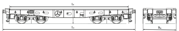
Fig. 1. Wagon
platform type S (Slmmps) [38]
Tab. 3
Technical
parameters of the flat wagon Slmmps [38]
|
The Flat
Wagon Series |
Designation |
Type S (Slmmps) |
|
Track width
(wheel spacing) |
Bt |
1.44[m] |
|
Length of
wagon with bumpers |
Lz |
12.34[m] |
|
Width of the
flat wagon |
Bw |
3.13[m] |
|
Cargo length |
Ll |
10.94[m] |
|
Maximum
speed |
V |
120[km/h] |
|
Minimum trackarc |
R |
75.0[m] |
The
weight of the armored vehicle "Rosomak" is
less than the maximum load capacity of the flat wagon, and the dimensions of
the wagon's loading flat are sufficient to place the armored vehicle "Rosomak" on it. The loading length of the flat wagon
is Ll = 10.9 m, with a loading width of
H=3.0m. When the length of the armored vehicle "Rosomak"
is LR = 7.88 m and the width BR = 2.83 m. The armored
vehicle "Rosomak" is produced in several
versions, differing in equipment. For the analysis, used the basic vehicle
version without a turret (Fig. 3). Each version has the same chassis layout and
towing eyelets as the basic version (Fig. 2) [37]. The weight of the
transporter changes, and the weight of the base vehicle is mL=22,500
kg and the combat weight of the turret is 2,900 kg (Tab. 4) [14].
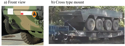
Fig. 2. Towing
eyelets in the armored vehicle at the front [37]
The
wheeled armored vehicle "Rosomak" does not
have special eyelets designed to secure the armored vehicle on the flat wagon.
Only the towing eyelets are used to analyze attachment to the flat wagon (Fig.
2). The wheeled armored vehicle has two towing eyelets in the front (Fig. 3)
and two towing eyelets in the back. In the front part, the towing eyelets are
located at a height of h1=1.24 [m], while the back towing eyelets
are located at a height of h2=0.9 [m] [14].

Fig. 3. The
Armored vehicle on a flat wagon; a) straight fixing S1, S2;
cross fixing S1, S2
Tab. 4
Details
parameters dimension of the wheeled armored vehicle „Rosomak”
[14]
|
Parameters
name |
Designation |
Value |
|
Mass of the
wheeled armored vehicle |
mL |
22 500[kg] |
|
Length of
the wheeled armored vehicle |
LV |
7.88[m] |
|
Width of the
wheeled armored vehicle |
Bw |
2.83[m] |
|
Min. height
of the wheeled armored Vehicle |
Hł |
2.14[m] |
|
Vehicle
height |
Hp |
3.30[m] |
|
Height of
the front towing eyelets |
h1 |
1.24[m] |
|
Height of
the back towing eyelets |
h2 |
0.90[m] |
|
Spacing of
the front towing eyelets |
Rp |
1.69[m] |
|
Spacing of
the back towing eyelets |
Rt |
1.69[m] |
|
Distance
between the towing eyelets |
Lu |
7.06[m] |
|
Distance to
the center of mass vehicle |
Cm |
3.76[m] |
3.1. Analysis
and selection of lashings for the armored transporter
on the flat wagon
The
analysis related to the selection of lashings for straight anchoring (Fig. 4a)
and cross anchoring (Fig. 4b) consists of determining the value of the lashing
capacity for each of the lashings placed at the front and the back of the
armored vehicle on the flat wagon.
The
input parameters needed to read the belt load are the mass of the loaded mL,
the angle α of the inclination of the lashing belt to the surface of the
flat wagon, the coefficient of friction μ between the load and the surface
of the flat wagon. The requirements related to securing loads are mainly based
on the EN 12663-1:2010 standard [5]. The European standard is based on a
coefficient based on empirical studies and presents a statistically estimated
value of the acceleration coefficient for means of transport (Tab. 2) [8]: cx
- acceleration coefficient in the direction of the x-axis for forward braking
and backward acceleration, respectively, maximum is cx=0.8 and a
railway maneuvering impact is maximum cx=4.0; cy –
acceleration coefficient in the centrifugal direction relative to the y-axis
and maximum is cy=0.8.
During
transport on a flat wagon, the load is subject to inertia forces in the
longitudinal direction (x direction) and transverse direction (y direction). In
the longitudinal direction, the load is subject to the force Fbx (Tab. 2), which occurs during braking or
when the wagon is maneuvered. When driving on a track arc, a transverse inertia
force is generated, which is the centrifugal force Fby
(Tab. 2). On the other hand, the uneven track is the source of the inertia
force Fbz, which acts vertically in the
form of vibrations. We will not analyze this force because of its low value.
According to the standard [4], the value of the inertia force is calculated as
the product of the acceleration coefficient cx,y
and the gravity force of the transported load QL[N] according to the
relationship (2):
|
|
|
|
(2) |
where: ![]() – acceleration coefficient to the x-axis on
railway arch,
– acceleration coefficient to the x-axis on
railway arch,![]() – acceleration coefficient to the x-axis on
emergency braking,
– acceleration coefficient to the x-axis on
emergency braking, ![]() – acceleration coefficient to the x-axis on
railway maneuvering,
– acceleration coefficient to the x-axis on
railway maneuvering, ![]() –
mass of the transported load.
–
mass of the transported load.
The
values of the acceleration coefficient are normalized for the individual
directions of the inertia force, and for a railway wagon, they are (Tab. 1)
[38].
Further
analysis took the coefficients cxH, cxM, and cyR
with the highest values, the most unfavorable moments that can occur in rail
transport.
In
railway transport, like road transport, various methods of securing loads on
the flat wagon can be used. The basic ones include [8]:
–
blocking;
–
anchoring using lashings (Fig. 4);
–
increasing the value of the friction force on
the flat floor of the wagon.
To
secure the wheeled armored vehicle "Rosomak",
the method of straight anchoring at the front and back (Fig. 4a) was compared
with the second method of cross-linking at the front and back (Fig. 4b). These
methods were chosen because of the location of the towing eyelets made by the
manufacturer. The straight method of fasting and the cross method of fasting
allow the armored vehicle carrier to be secured using four belt lashings. The
belt lashings secure the transported load against movement between the towing
eyelets and the handles on the flat wagon.
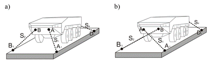
Fig. 4.
Fastening methods using straight anchoring (a) and cross anchoring (b)
After
analyzing these two methods, we will be able to answer the following question:
What forces act on the securing lashings in these two securing methods? That
is, what strength of the belt lashings will be used in the straight anchoring
method, and what strength in the cross-anchoring method? The wheeled armored
vehicle rests on the flat wagon on eight rubber-tired wheels. The friction
coefficient "µ" at the contact of two specific materials should be
determined according to the description given in the EN12663-1 standard [5]. In
our case, we do not need to use anti-slip mats, which are used to increase the
friction coefficient "µ". Cooperating materials are the rubber of the
transporter tires and the flat platform made of wood. The friction coefficient
of the materials is µ=0.6 for clean contact surfaces. In the case of a contact
surface covered with snow, ice, grease, or oil, the friction coefficient is
much lower according to the EN12663-1 standard [5].
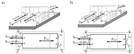
Fig. 5. Forces
acting in the direction of travel during braking and impact force during maneuvering; a) straight anchoring method; b) cross
anchoring method
The
load analyzed is secured using 4 lashing belts S1,
S2, S3, S4 connecting the flat wagon handles A1,
B2, C3, D4 with the towing eyelets of the armored vehicle A, B, C, and D. Two belts at the front S1,
S2 and two at the back S3, S4 according to the
diagram in the Tab. 4.
In
the longitudinal direction, the load is affected by the inertia force FbxH, which occurs during braking. When driving
in a track arc, the centrifugal force FbyR
is generated.
The
cross-anchored method (Fig. 6b) and the straight anchoring method (Fig. 6a)
were used to secure the armored vehicle. The
calculations are made for the straight and cross-anchored methods separately to
determine which of these methods causes smaller forces concentrated on the
belts fastening elements S1, S2, S3 and S4.
Both methods use four lashings S1, S2, S3, and
S4 which secure the armored vehicle
against movement in the longitudinal direction (direction x) and transversely
(direction y). In the longitudinal direction, the load is affected by the
inertia force FbxH, which occurs during
braking. When driving in a track arc, the centrifugal force FbyR
is generated (Fig. 6).
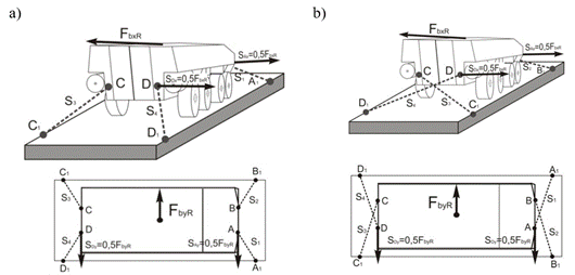
Fig. 6. Forces
acting in the transverse direction when driving on track arcs;
a) straight anchoring method; b) cross anchoring method
The
cross-anchored method (Fig. 6b) and the straight anchoring method (Fig. 6a)
were used to secure the armored vehicle. The
calculations are made for the straight and cross-anchored methods separately to
determine which of these methods causes smaller forces concentrated on the
belts fastening elements S1, S2, S3, and S4.
Both methods use four lashings S1, S2, S3, and
S4, which secure the armored vehicle
against movement in the longitudinal direction (direction x) and transversely
(direction y). The selection of cross and straight anchoring consists of
determining the minimum value of the securing lashing capacity (LC) for each of
the lashings S1, S2 placed in front and the back S3,
S4 of the armored wheeled transporter to
the flat wagon. To determine the lashing capacity (LC) of the lashings, an
inertial analysis of the transported load is necessary under the most unfavorable railway conditions.
The
calculations and analysis show that during braking and driving on a tracking
arc, the armored vehicle is subjected to the inertial
forces FbxH, FbxM,
FbyR which, according to the relationships
(1), (2) are, respectively (Tab. 5).
Based
on the calculation (Tab. 5), the result is that in the most unfavorable
braking conditions, the load is subjected to the inertia force of the maximum
value Fbxh=220,725[N], while in railway maneuvering work (where an impact occurs), the maximum
inertia force is FbxM=882,900[N]. On the
track arc, under the most unfavorable conditions, the
inertia force is FbyR=176,580[N].
Tab. 5
Maximum
inertial forces exerted on the wheeled armored
vehicle "Rosomak"
|
Driving
conditions (C-factor
value) |
The value of
inertial forces |
|
Braking for Ch=1,0 |
|
|
Maneuvering for CM=4,0 |
|
|
Track arc
for CR=0.8(centrifugal force) |
|
|
where: FbxH – maximum acceleration (deceleration)
value resulting from the movement of the flat wagon, FbxM
– maximum acceleration value at the moment of impact of the shunting of the
flat wagon. |
|
The
transported load is additionally counteracted by the friction force FT
between the wooden surface of the flat wagon and the tires. The friction force
FT is directed opposite to the direction of the inertia forces, so
the maximum inertia forces were additionally reduced by the friction force. The
friction coefficient µ between the wood and rubber material of the tires was
assumed for the most unfavorable conditions when the
surface is wet, and for these conditions, the friction coefficient µ=0.3 was
used for the calculations. In addition to these forces, in our case, the load
was also pressed by the tension of the belts S1, S2, S3,
S4. Then an additional pressure force Pn
acts on the load; that is, in addition to the gravity force G of the load, an
additional pressing force acts on the load. Belt tensions increase the pressing
force by the value Pn=5000N (in the STF
standard [lit] the tension force of the security belt is specified). After
taking into account this value of Pn in
the analysis, the friction force is FT (3):
|
|
where: mL
- the mass of the armored vehicle load, µ –
coefficient of friction between the tires and the platform of the flat wagon, Pn- the additional pressing force resulting from
the tension of the securing belts.
The
friction force after taking into account the load forces of the mass mL
[kg] and the pressing force Pn [N], the
determined friction force is FT=67,718[N] (3).
During
braking, the transported load of the armored vehicle
is secured by two lashings belts, S3 and S4 in the cross
method and the straight method also by two lashings belts S3, and S4.
On the arc to the right, they are secured by two lashings belts, S1,
S4 in the cross method and the straight method also by two lashing
belts, S1, S4. On the left side, the inertia forces are
concentrated on the lashing belts for the straight method S2, S3,
and in the cross method S2, S3. For the strength analysis
of the lashing belts, only one attachment point was taken, where half of the
force, acts on the inertia force, and the determined values are given in Tab.
6.
Tab. 6
The magnitude
of forces acting on a single belt tension in railway conditions
|
Transport conditions |
The
magnitude of the inertia force in one lashing belt |
|
Braking |
|
|
Maneuvering |
|
|
Driving on a
track arc |
|
Distribution
of forces for a single belt S4 (Fig. 7) of travel during driving on
a way arc in the most unfavorable railway conditions. Further analysis of the
strength capacity of the lashing belt was carried out for the lashing belt S4
attached between points D in the straight method (Fig. 7a) and C in the cross
method (Fig. 7b). In the cross analysis, the point of interest is the
attachment point C, and in the analysis of the partial attachment, we are
interested in point D (Fig. 7a) shows the distribution of force and
concentrating angles at point D of the lashing belt S4 (Fig. 7b)
(according to the formula (5)) in the cross method and shows the distribution
of forces and concentrating angles at point D on the lashing strap S4
(Fig. 7a) in the straight method (according to the formula (4)).
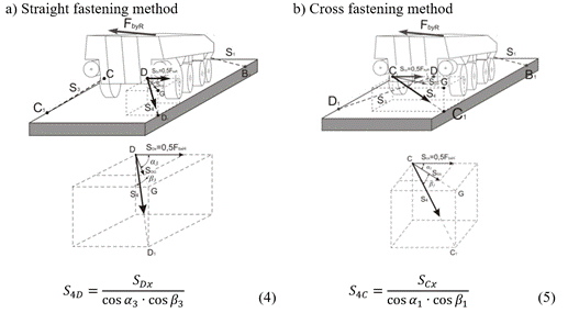
Fig. 7. Travel
during driving on way arc, force components of a single belt S4 at
the point of attachment D in the straight fastening method (a) and of the
tension S4 at the attachment point C in the cross-fastening method
(b)
Distribution
of forces for a single S4 belt in the direction of travel during
braking and impact forces during maneuvering (Fig.
8).
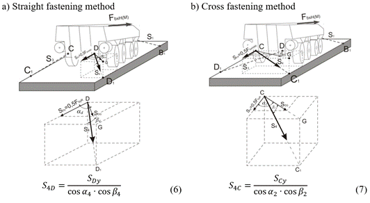
Fig. 8. Travel
during braking and impact forces during maneuvering,
the force components of a single belt S4 at the point of attachment
C in the straight fastening method (a) and of the tension S4 at
the attachment point D in the cross-fastening method (b)
In
the further part of the analysis, dependencies were determined that describe
the force acting on the S4 belt depending on the forces directed
along the braking direction SCx the forces
acting along the y direction for the SCy
force for the straight fastening method (Fig. 8a) and the corresponding SDy forces in the case of the cross-fastening
method (Fig. 8b).
The
values obtained for S1, S2, S3, and S4
are the forces concentrated in one lashing during maximum braking, maneuvering (impact force), and forces during driving on
the way arc in the most unfavorable railway
conditions. The force with the highest value has a decisive influence on the
strength value of the lashing belt used in the straight method and the cross
method (Tab. 7).
Tab. 7
The values of
inertia forces acting on the securing belts
|
Fixing method |
Number of the belt |
The
direction of driving a flat wagon |
The value of
maximum force in the single fixing belt |
|
|
S4 or
S3 |
The
direction of longitudinal movement at the moment of maximum braking. |
|
|
The
direction of longitudinal movement during maneuvering
works. |
|
||
|
S1 |
Driving on a
way arc to the right |
|
|
|
S4 |
|||
|
S2 |
Driving on a
way arc to the left |
|
|
|
S3 |
|||
|
|
S4 or
S3 |
The
direction of longitudinal movement at the moment of maximum braking. |
|
|
The
direction of longitudinal movement during maneuvering
works |
|
||
|
S1 |
Driving on a
way arc to the right |
|
|
|
S4 |
|||
|
S2 |
Driving on a
way arc to the left |
|
|
|
S3 |


The
calculation analysis presented in Tab. 7 shows that in the straight method of
lashing of the S3 and S4 fastening belts, under the most unfavorable railway conditions, the tensile force is at the
level of S3=S4=94,008N during extreme braking. The impact
force during the impact of maneuvering is at the
level of S3=S4=500,850N. On railway arcs, the tensile
forces are transferred by the S1 and S3 or S2
and S4 belts at the level of 183,766N.
In
the cross-fastening method in the direction of extreme braking, the tensile
forces are transferred by the S4 and S3 belts at the
level of S3=S4=176,677N. During the impact of maneuvering, the force level in the S3 and S4
fastening belts is S3=S4=941,292N. In extreme conditions
of railway arcs, the force concentrated on the S1 and S3
or S2 and S4 belts is 72,575N (Tab. 7).
3.2.
Selection of lashings securing belts for transported vehicle
For the
analysis performed with lashing, it is necessary to select the appropriate
lashing belts for the transmitted tensile forces under the most unfavorable transport conditions. It is necessary to select
the right lashing belt with an appropriate lashing capacity LC [7]. To secure
the armored vehicle, the generally available lashing
belts offered by manufacturers that produce according to the EN 12663-2
standard were selected [5]. Each belt is marked with the appropriate
information, which includes the following data: lashing capacity (LC) and
standard tension force (STF), which is obtained when a manual force (SHF) is
applied to the tensioner.
According to the manufacturers of chain lashings with
a turnbuckle, we can choose chains of lashings with chain class G8. In class
G8, the lashing strength capacity of the chains (LC) is from 40 kN to 106 kN (Tab. 8) [7].
Tab.
8
Fastening strap used for lashings S1,
S2 and S3, S4 [7]
|
|
Type |
Fixing capacity LC [kN] |
Nominal tension force STF [daN] |
|
ZRS G8 8 ZRS G8 8 ZRS G8 8 |
40 63 106 |
1
000 1
575 1
500 |

Based on these values, it can be seen that it is
not possible to select a chain lashing that secures the tensile force values in
extreme transport situations of the armored vehicle
load; this applies only to emergency braking and driving on a railway curve
(Tab. 8). In the cross-securing method, there is no possibility of securing the
chain lashing due to exceeding the permitted chain strength for emergency
braking and shunting maneuvers. For these force
values, only chain lashings with a strength of LC=106kN can be used, which is
carried out by a chain lashing type ZRS G8 8 (Tab. 8). In the cross-lashing
method, it can be seen that the situation is very similar, with the difference
that the force for extreme braking will increase for a single lashing S3 and S4
to a value of 176 kN. During the shunt, the force
will increase for S3 and S4 to a level of 941 kN. This value indicates that there is no single security
for this load during shunting operations for the cross-lashing method. These
forces can occur during the formation of railway wagons on railway sidings.
Only the forces on the railway curves, in the cross-lashing method, decreased
to a value of 72 kN (Tab. 7).
Figs. 9, 10, and 11 present the force values for
individual single forces that prevail in the lashing straps for extreme
conditions that can occur during extreme braking, driving on a curve, and
shunting that can occur in railway conditions for the simple and cross-lashing
methods.
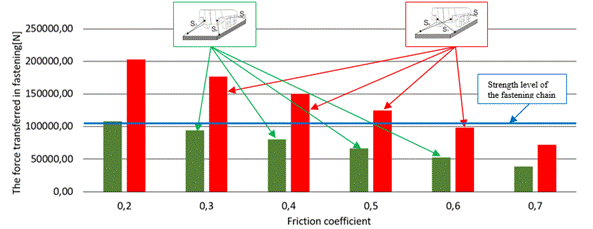
Fig. 9.
Diagram of forces during emergency braking
Based on the analysis conducted on the transport
of an armored personnel carrier weighing
approximately 22.5 tons, and after comparing the results presented in Figs. 9,
10, and 11, the following conclusions can be drawn. Assuming that the securing
chain strap has a lashing capacity of LC = 106 kN
(Tab. 7), only the straight securing method ensures that the load-bearing
capacity remains within limits, not exceeding the forces acting on the securing
straps during emergency braking. Even when the friction coefficient between the
wheels and the wagon surface is reduced to an extremely low value of µ = 0.2,
the inertial force remains equal to the load capacity of the securing chain
strap. However, in the cross method (commonly used to secure armored personnel carriers), a significant overload is
observed for friction coefficients between µ = 0.2÷0.7. Only when µ = 0.6 is
reached do the inertial forces equal the load capacity of the chains that
secure the armored vehicle. This indicates that when
the cross-securing method is used, particular care must be taken to ensure a
sufficiently high friction coefficient between the tires and the wagon surface.
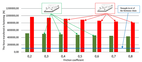
Fig. 10.
Diagram of forces during maneuvering work
However, the situation differs significantly
when conducting shunting operations with armored
personnel carriers. As shown in the analysis in Fig. 10, it is evident that
such operations are unacceptable for armored
personnel carriers. Both the straight and cross securing methods cause a
significant exceedance of the load-bearing capacity of the securing chains.
Based on the force distribution graph in relation to the friction coefficient
µ, it follows that such shunting operations are impermissible if the train
consists of cars carrying armored personnel carriers.
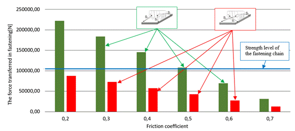
Fig. 11.
Diagram of forces during driving on a truck curve
Only
the cross-securing method
ensures the load-bearing capacity of the securing chains when traveling on railway curves in the worst-case
scenario (Fig. 11). This
suggests that the designers of the armored personnel carrier securing system
considered only protection on railway
curves. Within the entire range of µ=0.2÷0.7, the cross-securing
method prevents exceeding the load-bearing capacity of the securing
chains. The straight securing method
guarantees adequate securing only when
the friction coefficient exceeds µ = 0.5 (Fig. 11).
4. CONCLUSIONS
The
wheeled armored vehicle "Rosomak" is
standardly secured
using the cross-securing method
with four chain tie-downs or flexible
straps. This article analyzes the
forces acting on the tie-downs, which are concentrated in both the cross-securing and straight-securing methods. The
analysis compares the forces that occur in these two methods, the straight securing method and the cross-securing method, which is the standard approach to secure armored personnel carriers. In these securing methods, only
four chains or flexible straps
are used, with one tie-down at each
corner (S1,
S2, S3, and S4). Taking into
account the frictional forces of the load and the load-bearing capacity of the tie-downs
in relation to the main inertial
forces during the maximum
generation of impact force in shunting operations, the study
shows that these securing methods are
insufficient, as they significantly
exceed the load capacity of the securing chains. During sudden brakes of railway wagons,
only the straight securing method
is capable of effectively securing armored vehicles,
provided that an adequate friction
coefficient is maintained. The choice of securing method should
primarily depend on the inertial
forces acting on the transported armored vehicle
and should be preceded by a detailed
computational analysis.
The
analysis of securing the wheeled armored vehicle "Rosomak"
on a railway platform,
presented in Fig. 3,
shows that when using single securing
straps, different tensile force values occur depending on the
securing method, straight securing
(Fig. 3a) and cross
securing (Fig. 3b). Analysis reveals that in the straight securing method, the
highest tensile forces in the straps prevail
during shunting operations (impact conditions), reaching 500 kN. On the contrary, in the
straight securing method, during shunting operations (impact conditions),
the straps experience tensile forces of 941 kN.
In conclusion, based on the conducted analysis
of the wheeled armored vehicle, it appears reasonable to combine both straight and
cross-securing methods. This hybrid approach should be incorporated into the standard securing procedure for armored
personnel carriers. Future research by the authors will focus
on further analysis of the security of heavier
armored vehicles.
References
1.
Anderson N., P. Anderson, R. Bylander, S. Sokjer, Petersen and Bob Zether. 2004. „Equipment for
Rational Securing of Cargo on Railway Wagons”. VINNOVA. Report/Rapport
VR 2004:05.
2.
Azadi S., A. Jafari, M. Samadian.
2014. „Effect of tank shape on roll dynamic response of an articulated
vehicle carrying liquids”. International. Journal of Heavy Vehicle Systems 21(3): 221-240.
3.
Cieśla M., G. Hat-Garncarz. 2013. „The problem
of proper cargo securing in road transport – case study”. Transport Problems
8(4): 27-33.
4.
EN 12195-1:2011. „Load Restraining on Road
Vehicles – Safety – Part 1. Calculation of Securing Forces”. Brusel: European Committee for Standardization: 48.
5.
EN 12663-2:2010 Railway
applications – Structural requirements of railway vehicle bodies – Part 2:
Freight wagons.
6.
Grossmann G., M. Kassman. 2018. Transport
safe packaging and cargo securing. 3ed. Renningen:
Expert Verlag. ISBN: 978-3-8169-3334-2.
7.
Pewag. Available
at: https://security-chains.pewag.pl.
8.
IMO/ILO/UNECE. 2024. Code of practice for
packing of cargo transport units (CTU Code). United Nations Economic Commission for Europe. Available at: https://www.unece.org/fileadmin/DAM/trans/doc/2014/wp24/CTU.
9.
Jagelcak J.
2007. „Equation of the standard EN 12195-1 stipulates unreasonable demands for
cargo securing”. Komunikacie 9(4): 30-33. ISSN: 1335-4205.
10. Jagelcak J., J. Saniga. 2013. „Analysis of Elongation of Lashing Straps on
Movements of Cargo Secured by a Top-over Lashing at Sliding in Longitudinal
Direction”. Perner's Contacts 8(2): 53-62. ISSN: 1801-674X.
11. Jagelcak J., J. Gnap. 2011. „Different Measures for Load Securing Create
Barriers in International Road Freight Transport”. Archives of Transport Systems Telematics 4(2): 10-17.
12. Jagelcak J., J. Saniga. 2013. „Analysis of elongation of lashing straps on
movements of cargo secured by a top-over lashing at sliding in longitudinal
direction”. Perner's Contacts 8(2): 53-62. ISSN: 1801-674X.
13.
Jagelcak J.
2015. Loading and fastening of freight in road transport. 2nd edition.
ISBN: 978-80-554-1083-8.
14.
Kołowy
Transporter Opancerzony 8×8 „Rosomak”. 2004. Instrukcja eksploatacji. Opis i użytkowanie. Wojskowe Zakłady Mechaniczne S.A.
Siemianowice Śląskie. [|In Polish: 8×8 Wheeled Armored Personnel Carrier ”Rosomak”.
2004. Operation Manual. Description and
Usage. Military Mechanical Works
S.A. Siemianowice Śląskie].
15. Kwac L.K., J.Y. Kim, H.W. Kim, J.H.
Han, Y.S. Lee. 2006. „Stability analysis of dunnage for transportation of a
steel roll coil”. International
Journal of Modern Physics 20(25-27): 3769-3774.
16.
Lerher T.
2015. Cargo securing in road transport using restraining method with
top-over lashing. Nova. New York. ISBN: 978-1-61122-002-5.
17.
Loading guidelines. 2024. Section 2: Goods, UIC International Unions for Railway.
18.
Loading guidelines. 2024. Section 1: Principles,
UIC International Unions for Railway.
19. Nieoczyma A., J. Cabanb,
J. Vrabelc. 2019. „The problem of
proper cargo securing in road transport – case study”. Transportation Research Procedia 40: 1510-1517. DOI: 10.1016/j.trpro.2019.07.209.
20. Andersson
N., P. Andersson, R. Bylander, S. Sökjer, P.B. Zether. 2004. MariTerm
AB. Equipment for rational securing of cargo on railway wagons. VINNOVA. Report/Rapport VR. 2004:05. ISBN: 91-85084-07-7.
21. Olsen, A.A., F. Karkori.
2024. „General Load Securing Methods”. In: Containerized Cargo
Handling and Stowage. Springer Series on Naval Architecture, Marine
Engineering, Shipbuilding and Shipping. Springer. Vol 22: 333-359.
22. Olsen A.A., F. Karkori.
2024. „Load Securing, Filling Materials and Use of Friction”. In: Containerized
Cargo Handling and Stowage. Springer Series on Naval Architecture, Marine
Engineering, Shipbuilding and Shipping. Springer. Vol 22: 361-392.
23. Olszewski
Z., P. Krawiec. 2013. „Study of trailer lashing mechanical properties in terms
of transport safety”. Visnik Nacional Universitetu.
CDS-archive. Lviv Politehnika 777: 95-99.
24. Palúch S., Š. Peško,
T. Majer, J. Černý. 2015.
„Transportation network reduction”. Transport Problems 10(2): 69-74. ISSN: 1896-0596. DOI:
10.20858/tp.2015.10.2.7.
25.
PKP Cargo S.A. Instruction on loading and
securing freight shipments Ch-6. Annex to decision No. 19/2022.Ch-6. PKP CARGO S.A. Instruction on loading and
securing freight shipments.
26. Rievaj V., J. Vrabel,
F. Synak, L. Bartuska. 2018.
„The Effects of vehicle load on driving characteristics”. Advances in Science and Technology – Research Journal 12(1): 142-149. DOI:
10.12913/22998624/80896.
27.
Rozporządzenie
Ministra Infrastruktury z dnia 25 stycznia 2018 roku w sprawie sposobu przewozu
ładunku. Dz.U. 2018 poz.
361. [In Polish: Regulation of the Minister of Infrastructure of 25 January
2018 on the method of transporting cargo].
28.
Ruifang M.
2009. „Simulation Analysis for Cargo
Mechanical State during Transportation. Logistics. The Emerging
Frontiers of Transportation and Development in China: 821-827. DOI: 10.1061/40996(330)117.
29. Zasady przewozu wojsk transportem
kolejowym RON 9577 DU-4.4.1(B).2014. Warszawa. P:184. [In Polish: Rules
for the transportation of troops by rail RON 9577 DU-4.4.1(B).2014. Warsaw. P:184].
30.
Shtykov V.
P. 2014.„The carrier's liability for failure to vehicles to transport cargo”. Life Science Journal 11(9): 292-294.
31. Skrucany T., J. Gnap. 2014. „The effect of the crosswinds on the stability
of the moving vehicles”. Applied Mechanics and Materials 617: 296-301.
32. Turanov H., Y. Ruzmetov,
I. Dobychin. 2019.
„Fastening cargo on railway rolling stock”. XII
International Scientific Conference on Agricultural Machinery Industry. Conf.
Series: Earth and Environmental Science 403: 012206. DOI: 10.1088/1755-1315/403/1/012206.
33. Turanov K., E. Timukhina. 2008. „Analytical modeling
cargoes displacement in wagon and tension in fastening”. Transport Problems 3(3): 69-76.
34. Turanov Kh.T., E.N. Timukhina, D.V.
Volkov. 2007. „Loading capacities of flexible elastic fastening elements in
cargo location with mass center displacement
lengthwise the wagon”. Urals Transport 4:
25-35.
35. Turanov Kh.T., M.A.
Khadzhimukhametova. 2008.
„Mathematical modeling of cargo shift lengthwise the
wagon under the action of longitudinal and vertical forces”. Transport: Science, Engineering and Operation 7: 27-31.
36.
Vlkovský M., T. Ivanuša, V. Neumann, P.
Foltin, H. Vlachová. 2017.
„Optimizating cargo security during transport using
dataloggers”. Journal of Transportation
Security 10: 63-71. Springer. Science Business Media. DOI
10.1007/s12198-017-0179-4.
37.
Defence24. Available at: https://www. Defence24.pl.
38.
PKP
Cargo. Available at: https://www.PKPCargo.com.
39. Zamecnik
J., J. Jagelcak, S. Sokjer-Peterssen,
T. Hvojnik, M. Lipka. 2017. „Influence of a lashing
strap winding in tensioning ratchet on the results of the strength tests and
cyclic loading tests according to the standard EN 12195-2”. Communications. Scientific Letters
of the University of Zilina 19(2): 10-17. ISSN: 1335-4205.
Received 28.03.2025; accepted in revised form 05.06.2025
![]()
Scientific Journal of Silesian
University of Technology. Series Transport is licensed under a Creative
Commons Attribution 4.0 International License