Article
citation information:
Grega,
M., Brezinová, J. Causes of stress-relief cracks in forged differential gear. Scientific Journal of Silesian University of
Technology. Series Transport. 2025, 128,
83-94. ISSN: 0209-3324. DOI: https://doi.org/10.20858/sjsutst.2025.128.5
Marek GREGA[1], Janette BREZINOVÁ[2]
CAUSES OF
STRESS-RELIEF CRACKS IN FORGED DIFFERENTIAL GEAR
Summary. The article
investigates the formation of stress-relief cracking and lamellar cracking in
steel forgings used for differential gears for transport components. The
forging and heat treatment processes, conducted under consistent technological
conditions, revealed the occurrence of carburizing annealing cracks caused by
plasticity depletion during stress relaxation. Additionally, stress-relief
cracks were microstructurally analyzed, and the
primary cause of the disturbance of the equilibrium state, which resulted in
the formation of these cracks, was sought. Die-tool wear and damage during
forging were identified as key contributors to the formation of non-metallic
oxide inclusion, transferring surface defects and creating lamellar propagation
during subsequent heat treatment. The findings underscore the influence of
tooling conditions and process parameters on the quality and reliability of
steel forgings.
Keywords: stress-relief cracking, lamellar crack, forging, differential gear
1. INTRODUCTION
The increasing demands
for transmitting greater torque forces through differential gears bring many
challenges to the designers of individual components. Even proven processes for
producing precision drop forgings can ultimately introduce errors into subsequent
progressive methods of increasing the mechanical properties of steel, which can
ultimately be counterproductive due to material failure.
The production of a gear
wheel made of alloyed stainless steel for an axel - differential, represents a
technologically demanding process, wherein strict adherence to defined
manufacturing procedures is essential for ensuring the required quality of the final
product. The resulting properties of the components are significantly affected
not only by the applied technological operations but also by the precise
chemical composition and microstructural characteristics of the input material.
In conventional
industrial practice, the identification of latent defects during processing
remains a considerable challenge. In many cases, such defects become apparent
only during special processes, or final inspection and quality control
procedures. This necessitates detailed post-process analysis aimed at
identifying the root causes of the observed nonconformities.
Effective detection and
classification of defects in forged components require a systematic and
comprehensive approach to their typology. Among various defect types,
crack-like discontinuities are particularly problematic due to the complex and
multifactorial nature of their origin, which may involve thermal, mechanical,
or metallurgical influences throughout the entire manufacturing cycle.
A fundamental
classification of surface crack types is described in the EN 1011-2 standard
[5]. While this standard primarily addresses cracks arising during welding, it
is not limited to those occurring in welds but also includes cracks in the
heat-affected zones of parent metal. According to this standard, base materials
include not only sheets but also pipes and forgings. Categorized cracks based
on their temperature of origin during forging and their type—taking into
account orientation relative to the forging axis, location on the forged part,
and the forging method used [6,7].
Researchers Viňáš, Brezinová, Maňková, and Brezina [3] as well as researcher Brziak [4] adopted the basic classification of cracks from
the EN 1011-2 standard and further refined it into four primary groups, each
with subcategories. These groups include hot cracks, such as solidification,
liquation, and polygonization cracks. Cold cracks are a broad category without
subdivisions. Lamellar cracks are divided into exogenous and endogenous types
and annealing cracks, and have been a subject of study for many researchers.
Researchers Ito and Nawrocki investigated the mechanism of crack formation due
to stress relief [8, 13, 14].
Although the basic
mechanisms of stress-relieving annealing cracking are generally known and
extensively documented in the literature, the details of crack initiation and
the factors influencing them remain a matter of debate [10]. In general,
stress-relief cracking occurs when the stresses during annealing exceed the
local deformation capacity of the material [15].
The following mechanisms
are generally necessary for crack initiation:
- almost complete dissolution of carbides and carbonitrides in the
coarse-grained heat-affected zone;
- partial supersaturation of carbide-forming elements due to rapid cooling;
-
precipitation of
dissolved elements and formation of carbides in the matrix during subsequent
heat treatment.
The formation of these
cracks is associated with high-stress states in the carburizing zone during
phase transformations when cooling the materials above the heating temperature
Ms - 180°C. The temperature of heat treatment and holding time depend on the
chemical composition and especially on the material thickness. In cases where
the mechanical stresses are already too high, it can be necessary to perform a
so-called intermediate stress relief heat treatment [2, 10, 12].
Numerous research
results on precipitation behavior and carbide
development in low-alloy steels have been published in the last 60 years. While
there is agreement in the literature that crack initiation takes place during
the heating phase of the heat treatment, there are widely differing statements
on the critical temperature range of crack formation, from which a very broad
range between 315 and 705°C can be derived [11]. While the time-temperature behavior of carbide formation is documented in detail, the
influence of the forging process has so far received little attention.
All defects introduced
into the forgings during the forging process present a significant challenge in
the production of steel forgings, as defects can drastically affect the quality
and mechanical properties of the forged components. Such defects may lead to
product failure in applications subjected to high mechanical or thermal loads.
The paper presents the
results of research aimed at determining the causes of lamellar stress-relief
cracks in carburizing forgings.
2. MATERIALS
AND METHODS
Experimental observations of
defect occurrences were conducted on the product "gear wheell,"
designed for axle-differential applications for LKW and heavy-duty machinery.
The product features a simple geometric shape - a rotational disk with a central
hole and a non-uniform cross-section.
The product dimensions are as
follows: outer diameter - Ø 315 mm, inner diameter of the central hole -
Ø 658 mm, height - 60 mm, thickness - 30 mm, weight of the forging is
approximately 16 kg.
The forging is manufactured from
18CrNiMo7-6 steel, classified according to EN 10084:2008. Highly stressed
machine parts with a cemented surface. After heat treatment, the cemented layer
reaches a surface hardness of 62 up to 64 HRC, while the core of the cemented
part is quite tough even with relatively high strength.
This products from 18CrNiMo7-6
steel after forging are recrystallization heat treatment to achieve a
ferritic-pearlitic microstructure. Subsequently, they are subjected to
machining, hardening with cementation, and grinding to achieve the desired
roughness.
The technological and production
operations for the forging of the bearing ring are summarized in Figure 1. The heating of the billet is
performed in a gas furnace at a temperature range of 1150 to 1280°C.
The forging of the "gear
wheel" is carried out on a mechanical forging air hammer with a maximum
working force of 17 500 kN. The forging tools for this operation are designed
to combine two phases:
- pre-forging (open die): this phase involves reducing the
billet to the desired height of the preform and shaping it to prepare for the
next phase;
- final forging (closed die): this phase involves filling the
forging cavity to achieve the desired shape of the forging. The result includes
a slug for the central hole and flash along the edges of the forging.
Fig. 1. Final product – gear wheel
Subsequently, on a separate
machine – a mechanical press with a maximum working force of 15000 kN - the
forging undergoes flash and slug removal.
Tab. 1.
Technology operations overview
|
Working operation |
Material |
Working temperature [°C] |
|
Heating |
18CrNiMo6-7
+ U |
1150-1280 |
|
Forging |
18CrNiMo6-7 |
900-1150 |
|
Annealing |
18CrNiMo6-7 |
710-750 |
|
Tempering |
18CrNiMo6-7+FP |
550-690 |
|
Machining |
18CrNiMo6-7+FP |
20-30 |
|
Carburizing |
18CrNiMo6-7
+ gas |
930 – 940 |
|
Cooling |
18CrNiMo6-7
+ oil |
25-35 |
|
Quenching |
18CrNiMo6-7 |
830-840 |
|
Cooling |
18CrNiMo6-7
+ oil |
25-35 |
|
Tempering |
18CrNiMo6-7 |
180 |
|
Griding |
18CrNiMo6-7 |
20-30 |
After the forging process, the product undergoes heat
treatment, beginning with recrystallization annealing in continuous gas
furnaces equipped with electronically controlled temperature regulation
systems, in accordance with the DIN 17052-1 standard (Requirements for
temperature uniformity). The treatment is carried out at a temperature of
750 °C with a holding time of 200 minutes.
Following controlled cooling, the forgings are
subjected to shot blasting to remove surface contaminants and prepare them for
final quality inspection. Non-destructive testing is then performed,
specifically visual inspection in accordance with the EN 13018 standard.
Subsequently, the forgings undergo machining operations, including turning and
milling.
The next stage of heat treatment involves gas
carburizing. The components are placed in a furnace and exposed to a controlled
carbon monoxide atmosphere. The furnace is heated to a temperature range of
930–940 °C, corresponding to the austenitic phase region of the steel.
The carbon potential of the atmosphere is precisely regulated to achieve a
target surface carbon concentration of approximately 0.5%. The required
effective case depth of carburizing is in the range of 1,1-1.5 mm.
Following carburization, the parts are rapidly cooled
by oil quenching, transforming austenite into martensite and thereby increasing
surface hardness. The quenched components are then quenched and tempered at a
lower temperature (e.g., 180 °C) to relieve internal stresses and improve
toughness.
The subsequent processing step is grinding, which
ensures the desired surface finish and dimensional accuracy. The final process
is non-destructive testing (NDT) - a visual inspection of the pieces to detect
any defects.
To evaluate the mechanical properties, chemical
composition, and microstructural characteristics, a cross-sectional specimen
was prepared for analysis. The chemical composition was determined using
optical emission spectroscopy. The results, presented in Table 2, confirm that
the elemental composition of the material falls within the specified limits for
18CrNiMo7-6 steel and for the carburization layer of this steel.
The obtained measurement results fall within the
specified tolerance limits, confirming compliance with the prescribed quality
criteria. The applied technological procedures led to the achievement of the
required mechanical and structural properties in both the base material and the
cemented surface layer. Detailed results are presented in Table 2 and 3. The
base material, prior to mechanical processing, exhibited the prescribed
microstructure, hardness, and chemical composition. Subsequent heat treatment processes
resulted in the formation of a martensitic cementation layer on the material
surface, with a depth of approximately 1.5 mm, as required.
Tab.
2.
Chemical analysis of two different zone (wt.%, Fe balance)
|
Chemical element |
Core material
[wt.%] |
Carburized layer
[wt%] |
|
C |
0.17 |
0.46 |
|
Si |
0.27 |
0.27 |
|
Mn |
0.56 |
0.55 |
|
P |
0.010 |
0.009 |
|
S |
0.009 |
0.009 |
|
Cr |
1.63 |
1.61 |
|
Mo |
0.276 |
0.275 |
|
Ni |
1.58 |
1.55 |
The aim of the research is to verify the primary cause
of cracks in cemented forgings, based on empirical observation using laboratory
microstructural and other analyses. The Brinell hardness test was conducted in
accordance with EN ISO 6506-1 method HBW 2,5/1850/10. The microstructure
materials were observed under an optical microscope at 500x zoom, on an etched
sample with 5% Nital taken directly from the crack location. The microstructure
of the crack was observed under optical microscope at 200x zoom. Final quality
control was performed using Non-Destructive Testing (NDT) - Visual Testing (VT)
was according to EN 13018.
Tab. 3
Test results
|
|
Core material
|
Border zone |
Carburized layer
|
|
HBW |
361 |
428 |
570 |
|
Type of microstructure |
Ferit-perlite |
Upper bainite |
Tempered martensite |
|
Thickness of layer [mm] |
0-30 |
0.1-0.2 |
1.1-1.5 |
3. RESULT
An VT analysis was conducted of 293 pieces. The number of defective
forgings after each inspection phase were 21 pc, that is 7,17% scrap forgings.
|
|
|
|
(a) |
(b) |
Fig. 2. Inspected forging in visual testing (VT): a) Location of cracks on
forging;
b) Location of cracks on forging in section
The cracks are localized on the bottom and upper sides
of the forging (Figure 3, zones A and B). The length of the cracks ranged from
40 to 120 mm (Figure 2a,b). The depth of this crack ranges from 0 to15 mm.
These cracks were observed only in special zone with radius R6 mm in part of
its perimeter. The start of the crack (Figure 2a) is on surface R6, and
progression is lamellar toward the outer side (Figure 2b) of the forging.
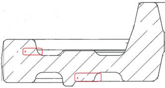
Fig. 3. Localized
crack after VT only in two zones, A and B (red color
on section scheme)
Fig. 4. Length
crack in zones A
The direction of the cracks is parallel to the surface
of the hardened layer. On macroscopic
observation of the crack – Fig. no. 4 and 5, an oxide layer is clearly visible
along its entire length. The crack starts in the martensitic structure and runs
and ends in the bainite microstructure - boundary zone. The start of the cracks
is on the surface at a radius of R6, on the forgings.
Fig. 5. Macroscopic observation of the steel structure
The crack is bounded along its entire length by an
oxide layer (Figure 5 up), beneath which a gradual intergranular breakdown of
the bainitic structure is observed.
The observed
microstructure differs depending on which part of the forging layer it is
located.
-
The Core – Ferrite and Pearlite (Figure 6a)
is the core microstructure of the steel, which remains unaffected by the
carburizing and hardening treatments. It consists of a fine-grained
ferrite-pearlite structure with evenly distributed phases. The light-colored
ferrite matrix is interspersed with dark, lamellar pearlite colonies. This
microstructure offers good toughness and machinability, although it has
relatively low hardness compared to the surface.
-
Surface Layer – Tempered Martensite (Figure
6b), which is a fine, needle-like structure typical of tempered martensite,
which dominates the carburized and quenched surface layer. The structure
appears uniform and relatively dense, with possible traces of retained
austenite in certain regions. The martensitic needles are tempered, indicating
that the sample underwent a post-quenching tempering process. This
microstructure is associated with high surface hardness and wear resistance,
which is essential for the functional performance of case-hardened components.
|
|
|
|
(a) |
(b) |
Fig. 6. Microscopic structure (200x zoom):
(a) ferrite-perlite structure; (b) tempered martensite structure
- Border
zone – Upper
Bainite (Figure 7) is the transition region between the hard case and the
softer core. The microstructure consists primarily of columnar and equiaxed
bainitic laths, which nucleate intragranular due to the presence of
non-metallic inclusions. These grains are randomly oriented, providing
isotropic mechanical properties. The lath-like morphology is characteristic of
transition zones cooled at moderate rates, which prevents the formation of
coarse pearlite or martensite. This gradient zone results from decreasing
carbon content and a reduced cooling rate with depth. It exhibits a mixed
microstructure comprising:
• upper bainite, which appears darker and more compact;
• acicular ferrite with minor polygonal ferrite;
• in this zone oxide inclusion are observed.
Fig. 7. Microscopic observation of the borderline structure – bainite
The combination of different microstructures across the case depth – tempered
martensite at the surface, a martensite-bainite transition zone, and a
ferrite-pearlite core – demonstrates the effectiveness of the applied
thermochemical treatment in tailoring the performance of 18CrNiMo6-7 steel.
Fig. 8. Microscopic observation of the zone microstructure
To evaluate the heat
treatment process and separate microstructure zones a hardness test was
performed on a cross-section of the forging. The individual measurement values
are presented in Table 3. Based on this measurement, the depth of individual
microstructural zones was determined, as well as the depth of the crack in the
forging.
4. DISCUSSION
Based on the evaluation of the test results and
laboratory analyses of the location, direction, and size of the cracks, it can
be concluded that this type of crack propagated in the material during heating
during steel carburization. Since oxide inclusions are present on both sides of
the crack, it initiated in the heat-affected zone of the carburization zone of the steel. The main
cause of the growth of these cracks is the loss of plasticity in the critical
zone of the heat-affected zone during the carburization process, namely during
the relaxation of residual stresses [2].
A detailed visual examination of the crack (Figure 9a,
b) on the surface of the forging revealed that it was formed by sharp notches
that penetrated the surface layer at radius R6 and thus disrupted its
integrity. The inclusion material consisted of oxide scale residues that had
entered the layer of the base material during forging. The shape of the oxide
scale is flaky, and when mixed into the surface of the steel forging, a surface
groove is created. The oxide scale was removed from the surface of the forging
during the blasting operation, but traces remained in the form of notches and
grooves.
|
|
|
|
(a) |
(b) |
Fig. 9. Detail from a visual inspection
of initial cracks on the surface:
(a) oxide scale in radius R6; (b) sharp notches on the surface
It is important to note that these stress-relieving
cracks are only a consequence of the introduction of oxide inclusions into the
surface of the forging and thus the creation of a notch concentrator of excess
stress during the forging process in the austenitic phase [9]. The places of
introduction of oxide inclusions are defined in two specific zones of the
forging in local radii on the upper and lower parts of the forging. It should
be noted that the material flow in the forging process causes abrasive wear of
the dies, which, if not properly maintained, can cause a reduction in the
radius of the radii and thus the formation of a place where oxide inclusions
occur more frequently. Oxide inclusions are subsequently transferred from the
die to the forging when the material in the austenitic phase does not flow
properly. Mold failure in hot forging is complicated by various types of
influencing variables, such as mold material, mold design, mold manufacturing,
and forging operations [1]. Structural disharmony together with the notch
effect on the surface of the forging leads to the formation of microcracks,
which act as precursors to crack formation in the following heat treatment.
5. CONCLUSIONS
Stress-relief cracking is widely recognized as a
phenomenon primarily induced by the synergistic effects of residual stresses,
microstructural transformations along grain boundaries, and suboptimal thermal
cycles during heat treatment. In the batch production of carburized forgings,
even when technological parameters are correctly set, external and
process-related variables can lead to significant quality issues and economic
losses due to defect formation and product nonconformity.
The borderline bainitic microstructure is
intentionally developed to withstand residual stress accumulation after the
heat treatment of forgings between martensite and ferrite-perlite structures.
Nevertheless, the integrity of this structure can be compromised by the
presence of non-metallic oxide inclusions at the surface, which disrupt the
structural continuity. These inclusions act as initiation sites for lamellar
cracking, particularly at the interface between the carburized surface layer
and the core material exactly in bainite structure.
The root cause of this degradation mechanism lies in
the wear of the forging die, especially in regions with defined radii. During
hot forging, steel is plastically deformed to its final geometry by filling the
die cavities at elevated temperatures. The combined effects of thermal
exposure, repeated mechanical impacts, and abrasive action result in the
progressive deterioration of the die surface, leading to the formation of
oxidized scale zones.
This degradation subsequently facilitates the
entrapment of oxide scale within the surface layer of the forging and promotes
the formation of stress concentrators such as notches. During subsequent heat
treatment, these surface discontinuities serve as preferential sites for crack
initiation and propagation. The presence of such defects significantly
compromises the structural integrity of the forgings, adversely affecting their
functional reliability in service conditions.
Funding
This
research is the result of the project supported by the Slovak Research and
Development Agency, the Scientific Grant Agency “Possibilities of application
of laser additive technologies in restoration of functional surfaces”
(1/0597/23), the Cultural and Educational Grant Agency “Hybrid student
education for current automotive industry needs” (024TUKE-4/2025) and
"Innovative approaches in the restoration of functional surfaces by laser
surfacing" (APVV-20-0303).
References
1.
Bílik, J. 2027. Teoretické A Technologické
Aspekty Mechanického Spevňovania Povrchových Vrstiev. AlumniPress, STU, Trnava, Slovakia. ISBN:
978-80-8096-020-9. [In Slovak: The Theoretical and Technological Aspects
of Surface Layers Mechanical Strenghtening].
2.
Bentley K.P. 1964. Precipitation
during stress relief of welds in Cr - Mo - V steels. Br Weld J. P. 507-515.
3.
Brezinová J., J. Viňáš, D. Draganovská, A. Guzanová. 2020. Základy materiálového inžinierstva. Study
literature edition. Košice, Slovakia. ISBN:
978-80-553-3745-6. P. 256-273. [In Slovak: Fundamentals
of Materials Engineering].
4.
Brziak P., et al. 2020. Materiály a ich správanie sa
pri zváraní. Welding Research Institute
- Industrial Institute of the Slovak Republic, Bratislava Slovakia. ISBN: 978-80-96933-09-9. [In Slovak: Materials and their behavior
during welding].
5.
ČSN EN 1011-2:2002/A1. Svařování - Doporučení pro svařování
kovových materiálů - Část 2: Obloukové svařování feritických ocelí. Praha: Czech Norms Institute.
[In Czech: Welding - Recommendations
for welding of metallic materials - Part 2: Arc welding of ferritic steels].
6.
George E. Dieter. 1993.
“Material Factors Affecting Workability”. ASM Handbook Forming and Forging
14: 782-794.
7.
George E. Dieter. 1993.
“Forging Defects”. ASM Handbook Forming and Forging 14: 834-841.
8.
Ito Y., K. Bessyo K. 1968. “Cracking parameter of high strength steels
related to heat affected zone cracking”. Journal of the Japan Welding
Society 37(9): 983-991. DOI: 10.2207/qjjws1943.37.983.
9.
Kotecki D.J. 2016. “Fourth
round robin report-trace elements in Cr-Mo-V steel weld metal”. Weld World
60(4): 639-643.
10. Kromm Arne, Thomas Lausch, Dirk Schroepfer, Michael Rhode,
Thomas Kannengiesser. 2020. “Influence of welding stresses on relief cracking
during heat treatment of a creep-resistant 13CrMoV steel Part II: mechanisms of
stress relief cracking during post weld heat treatment”. Welding in
the World 64: 819-829. DOI: 10.1007/s40194-020-00881-8.
11. Kroupa A., A. Výrostková, M.
Svoboda, J. Janovec. 1998. “Carbide reactions and phase equilibria in low-alloy
Cr–Mo–V steels tempered at 773–993 K. Part II: theoretical calculations”.
Acta Materialia 46(1): 39-49. DOI: 10.1016/S1359-6454(97)00239-5.
12. Nakamura N., T.
Wnjo, Y. Kikuchi. 1992. „Effects of heat-affected zone microstructure on
reheat cracking susceptibility of Cr-Mo steels”. Weld Int 6(6): 436-442.
13. Nawrocki J.G., J.N. DuPont, C.V. Robino, J.D. Puskar, A.
Marder. 2003. “The mechanism of stress-relief cracking in a ferritic alloy
steel”. Welding Journal (Miami, Fla) 82. 25/S-35/S.
14. Nawrocki J.G. 2002. “Stress-relief cracking of a
ferritic alloy steel”. Welding Research Abroad 48: 16-23.
15. Tamaki K., J. Suzuki. 1983. “Reheat cracking test on
high strength steels by a modified implant test – (Study of reheat cracking of
Cr-Mo steels, Report I)”. Trans Jpn Weld Soc Bd
14(2): 33-38.
Received 11.06.2025; accepted in revised form 10.08.2025
![]()
Scientific Journal of Silesian
University of Technology. Series Transport is licensed under a Creative
Commons Attribution 4.0 International License