Article
citation information:
Caban, J., Nieoczym, A.,
Matijošius, J., Kilikevičius, A., Drozd, K. Analysis of the construction
of the car trailer frame in terms of changing the assembly technology. Scientific Journal of Silesian University of
Technology. Series Transport. 2024, 124,
47-61. ISSN: 0209-3324. DOI: https://doi.org/10.20858/sjsutst.2024.124.4.
Jacek CABAN[1],
Aleksander NIEOCZYM[2],
Jonas MATIJOŠIUS[3],
Artūras KILIKEVIČIUS[4],
Kazimierz Drozd[5]
ANALYSIS
OF THE CONSTRUCTION OF THE CAR TRAILER FRAME IN TERMS OF CHANGING THE ASSEMBLY
TECHNOLOGY
Summary. Car trailers are quite
a popular means of transport and are offered in many versions, from single axle
light trailers with a maximum permissible weight of 750 kg, through two- or
more-axle specialized trailers. The issues of research car trailers focus on two
directions: testing the driving properties and analysing the strength of the
supporting frame system. Issues related to the construction of light trailers
are often common to trailers used in agriculture or general transport. In this
article, based on a mass-produced car trailer, an analysis was carried out
regarding the choice in the technology of making the supporting structure
consisting of a lower frame and an upper frame. The term upper frame should be
understood as the structure on which the lifted load box rests. The costs of
materials, assembly and technological possibilities of small-scale production
were taken into account. In addition, strength analyses of the numerical models
were carried out for critical areas of the frame during operation. After
considering the unit costs for each of the analysed assembly technologies, it
was shown that riveting would be the cheapest. However, the most suitable
method of assembly is welding, as it allows the use of standard profiles.
Keywords: road vehicles, montage, joining, strength
analysis, production costs
1. INTRODUCTION
Road transport is the most popular type of
transport for moving people and goods. It provides great freedom of movement,
and the multitude of means of wheeled transport makes it quite universal. An
additional advantage is the possibility of connecting the vehicle with a
trailer, which increases the usability in the field of transporting various
goods. Car trailers are quite a popular means of transport and are offered in
many versions, from the simplest single-axle light trailers with a gross
vehicle weight of 750 kg, through two- or more-axle specialized trailers. As
noted by Ladra and Posiadała [13], however, many car trailer solutions are
dedicated to specialized transport, which limits the construction of trailers
to specific types of transport, i.e. very often they are only single-purpose
trailers.
In the publications on car trailers, two topics
dominate: the study of driving properties and the analysis of the strength of
the supporting frame system.
The study of the system: vehicle-trailer in
terms of dynamics is performed due to the requirements related to driving
safety [11, 17, 25, 26]. In the work [28], it was found that axle load transfer
and braking force distribution have a large impact on the dynamic stability of
the combine: a vehicle with a single axle trailer. The stability of the vehicle
and the vehicle with a trailer was also analysed in the following works [2, 12,
22]. The published results are frequently used in general issues of vehicle
motion concerning the behaviour of the vehicle when driving on unevenness and
on a curvilinear track. For example, articles [1, 29] present the results of
dynamic tests of a single-axle trailer when driving through a simulated
obstacle. It was shown that the system did not reach the highest acceleration
values (the most important for safety of the cargo) when the wheel hit the
obstacle, but only when the trailer later bounced off the road. Another aspect
of road safety is the effects of a collision with a vehicle towing a trailer [19]
and the stability of the load carried on the trailer loading platform [5].
Noteworthy are publications [23, 27] where the authors included simulations of
load displacements under the influence of dynamic impact caused by a road
collision.
The second issue is related to the strength
analysis of designed trailers or activities aimed at modifying existing
structures. The published research results are mainly related to the designs of
specialized trailers that are not included in the sales offer [10]. Another
example is the design of a multipurpose light trailer [14], which combines
structural solutions used in trailers for transporting small loads,
motorcycles, quads, or kayaks.
Issues related to the construction of light
trailers are often common to trailers used in agriculture or general transport.
An example is the strength analysis of the frame of a single-axle tractor
trailer [4]. There are maps of stresses and displacements of the frame with the
indication of detailed load cases affecting the strength. The methodology for
optimizing the dimensions of the beams forming the trailer frame is contained
in publication [16]. The authors presented the results of their work based on the
frame of a specialist trailer designed to transport rolls of straw. Aimed at
minimizing the weight of the frame while meeting the strength limitations, it
was carried out in two procedures: changes in the thickness of the profile
walls and the use of steel profiles and a different shape of the cross-section.
Due to the stability of the transported load on the trailer, an important issue
is to determine the centre of gravity [18, 20, 24]. The variables here were:
the type of trailer and the weight and dimensions of the load.
Most of the large trailers and semi-trailers
are made of steel sheets and cold bent metallurgical steel profiles, made in
the technology of welding and riveting. Smaller car trailers are made of
standard steel profiles, and sometimes composite materials are used. The frames
of these trailers are made in the technology of welding, riveting or by means
of threaded connections.
In this article, based on a small-scale
produced car trailer, an analysis was carried out regarding the change in the
technology of making the supporting structure consisting of a lower frame and
an upper frame. The term upper frame should be understood as the structure on
which the lifted load box rests.
2. Methodology
The main purpose of the work was to
indicate whether it is possible to change the production technology of the
load-carrying system of a self-dumping car trailer. For this purpose, solid
models of trailer frames were made in three different technologies: riveting,
bolting and welding, as well as a strength analysis was carried out using the
finite element method (FEM).
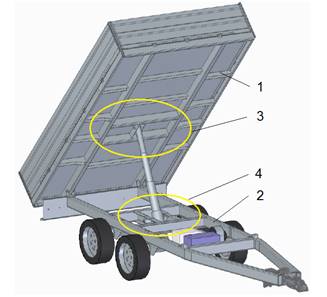
Fig. 1. Axonometric
view of the trailer in the maximum lift position: 1 – upper frame,
2 – lower frame, 3 – actuator mounting node in the upper frame, 4 – actuator
mounting node in the lower frame
The modified trailer is a two-axle
self-dumping trailer equipped with a hydraulic cylinder. The permissible total
weight of the trailer is m = 2000 kg.
The strength analysis using FEM was carried out for the initial moment of the unloading
process, i.e. when the cylinder piston rod advances and the upper frame is
raised. Then, the sup-port points of the load box frame are changed, and the
load is transferred to the nodes (Fig. 1, items 3, 4) in which the cylinder is
mounted. The load on these elements’ changes with the change of the angle of
the upper frame, and the maximum value is recorded for the angle value in the
range of 1.0°-1.5° [4, 15].
In each of the three cases of
design, it was assumed that the frame elements are made of S335JR structural
steel with a yield strength of Re =
355 MPa. During the FEM strength analysis, a 3 mm hex sweep mesh was applied to
all elements. The number of finite elements was equal to 358,557. The load to
which the frame models were subjected reflected the case of a uniformly
distributed load in the volume of the load box. The maximum force in a
hydraulic cylinder resulting from the permissible load weight is equal to F = 17,000 N.
The next step was to prepare
technical documentation containing lists of beams of the upper and lower
frames, indicating whether they are standard profiles or made of sheets of
steel. The last stage of the study was to analyse the costs of making trailer
frames for the three indicated manufacturing technologies.
3. Results
and Discussion
3.1. The construction of frames made
in the technology of twisting
The load bearing structure of the
original trailer frame (Fig. 2) is made in the connection technology with the
use of M8 bolts and nuts. The sleeve with an outer diameter of 14 mm and a wall
thickness of 1.8 mm is used to increase the rigidity of the structure (Fig. 3).
Thanks to the sleeves, the connected channels are not deformed when tightening
the fasteners.
|
|
|
|
(a) |
(b) |
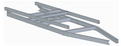
Fig. 2. Trailer frame
assembled using threaded connections: a – general view, b – assembly node using
a screw connection: 1, 2 – connected C-sections, 3 – screw, 4 – nut, 5 – sleeve
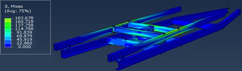
Fig. 3. Stress
distribution in a solid model of frames made by bolted connections
The FEM strength analysis was
carried out at the time of initiation of the load box lifting process. The
stress distributions in the frame assembly are shown in Figure 3 and Figure 4
shows the distribution of stresses in the cylinder mounting actuator node

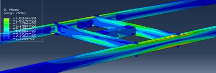
Fig. 4. Stress
distribution in the cylinder mounting nodes: a) in the upper frame,
b) in the lower frame
The maximum stresses are generated
on the upper surfaces of the side members and crossbeams of the upper frame and
reach the value of 183 MPa. This condition is typical for a model of a bending
beam subjected to a continuous load along its entire length. Lifting the load
box causes the actuator to take over the load resulting from the weight of the
load, and the resulting reaction forces concentrate on the sockets that are the
support areas of the lifting unit. High-stress values in these areas also
result from the small contact area – the thickness of the beam walls is 4 mm.
It should be noted that the high values of compressive stresses arising in the
sleeves mounted on the connecting bolts – they reach a value of approx. 120
MPa.
The strength analysis of the
original semi-trailer frame made in the bolted connection technology was aimed
at identifying the places of maximum stress. These places will be treated as a
reference during strength analyses of frames made in different assembly
technologies.
3.2. The construction of frames made
in welding technology
The distribution of stresses in the
frame assembly is shown in Fig. 5. It should be noted that the stress maps are
identical to those in the bolted frames (Fig. 3, 4) despite the use of other
beam profiles (see sections 3.4.1 and 3.4.2), with a decrease in the value of
the maximum stresses (to 169 MPa) reduced by approx. 15 MPa. The most heavily
loaded elements in the upper and lower frames are the hydraulic cylinder
mounting sockets (Fig. 6, items 1, 2) made in channel sections. The next
surfaces where comparable reduced stresses are recorded are the upper and lower
planes of the stringer and crossbeam of the upper frame. Maximum stresses occur
in the middle of its length (Fig. 6, item 3).
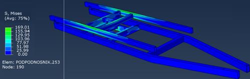
Fig. 5. Stress maps on
the assembly of trailer frames made by welding
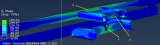
Fig. 6. The place of
maximum stress in the lower frame – the cylinder socket: 1 – actuator mounting
location in the lower frame, 2 – cylinder mounting hole in the upper frame,
3 – structural element of the upper frame
3.3. The Construction of frames made
in riveting technology
Another modification entails
connecting steel profiles with blind rivets. The use of the riveting machine
made it necessary to change the profiles of the crossbeams and longitudinal
beams of the upper and lower frames forming the cylinder mounting nodes (see
section 3.4.3). Rivets with an outer diameter of 6.4 mm made of stainless steel
A2 [3] were used to connect the frame elements. Three rivets were used in each
fastening node (Fig. 7, item 1, 2). They have been arranged so that the
production worker is able to fit a pneumatic riveter with a standard head
diameter.
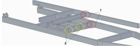
Fig. 7. Trailer frame made with the use of
riveted connections: 1 – connecting the crossbeams to the stringers, 2 –
connecting the longitudinal beams of the cylinder mounting node to the crossbeam
The strength analysis was also
carried out for the situation where the angle between the upper and lower
frames was 1.5°. The distribution of stresses on the stringers and crossbeams
of the upper frame and in the sockets of the cylinders are identical to those
in the bolted and welded frame, but the maximum values of reduced stresses are
not observed here – Fig. 8
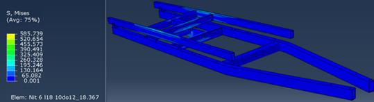
Fig. 8. Stress maps on
the assembly of trailer frames made by riveting
On the cylindrical surfaces of the
rivets, the stresses caused by shear and surface pressures reach the value of σ = 585 MPa (Fig. 8, 9). The rivet material has a yield strength of Re = 450 MPa. Therefore, the possibility
of changing the frame production technology by joining with bolts and nuts for
riveting should be rejected. The rivet is a critical element that determines
the strength of the structure.
|
|
|
|
(a) |
(b) |
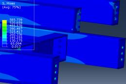
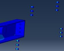
Fig. 9. Distribution of
stresses in rivet nodes: (a) stresses in the rivets fixing the crossbeams
to the longitudinal members of the upper and lower frames (Fig. 7, area 1);
(b) view with hidden longitudinal beams
Below is a list of profiles used to
make the lower and upper frames in three assembly technologies. It was assumed
that the cost of making the loading box, the drawbar, and the cost of
purchasing the complete axle remain unchanged. Dimensions of U-shaped and
rectangular sections, sheets and standard parts, as well as their prices, were
taken from sources [24-27]. The costs of works related to laser cutting,
riveting and welding are approximate costs estimated on the basis of
information contained in [6, 21].
|
|
|
|
(a) |
(b) |
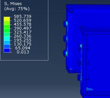
Fig. 10. Distribution
of stresses in rivet nodes: (a) stresses in the rivets connecting the cross-beams
with the lifting elements (Fig. 7, area 2); (b) view with hidden crossbeams
3.4.1. Original frame
Figure 11 shows the upper and lower
frames made in the technology of screw joints. Table 1 presents a list of
materials needed for the production of car trailer frames made in the
technology of bolting.
|
|
|
|
(a) |
(b) |
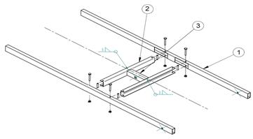
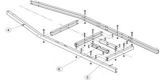
Fig. 11. The frame
made in connection technology with the use of bolts and nuts:
(a) upper frame; (b) Lower frame. The beam numbers on the references correspond
to the ordinal numbers in Tab. 1
The elements listed in table 1 marked with the order number 2, 5, 6 will be made of sheet metal. The following sheets can be used for production:
- 3 mm thick
sheet, dimensions 1 x 2 [m] – sheet price: EUR 81.2,
- 4 mm thick
sheet – sheet size 1 x 2 [m] – sheet price: EUR 96.15.
Dimensional analysis indicates that
half a sheet of 3 mm thick and 4 mm thick should be used. So the cost of the
material will be 88.67 EUR.
The cost of laser cutting depends on
the thickness of the sheet:
- 3 mm thick
sheet, dimensions – 2.14 EUR/mr,
- 4 mm thick
sheet dimensions – 3.85 EUR/mr.
Tab.
1
List of materials needed for the
production of frames made in the technology of bolting
|
No. |
Element |
Dimensions [mm] |
Length [mm] |
Quantity |
Unit price [€/mr] |
Value [€] |
|
|
Upper frame |
|||||
|
1 2 3 |
Rectangular section profile |
80x40x3 |
2520 |
2 |
7.70 |
38.80 |
|
C-section profile |
74x50x3 |
711 |
2 |
Made of sheet metal |
||
|
C-profile |
60x40x4 |
260 |
1 |
5.76 |
1.50 |
|
|
Lower frame |
||||||
|
4 |
C-profile |
100x50x4 |
3600 |
2 |
11.75 |
84.60 |
|
5 |
C-section profile |
86x54x4 |
700 |
3 |
Made of sheet metal |
|
|
6 |
C-section profile |
80x54x4 |
480 |
2 |
Made of sheet metal |
|
|
Connecting elements |
||||||
|
7 |
Bolt M8 x100 |
|
|
4 |
0.96 |
3.84 |
|
8 |
Bolt M8 x120 |
|
|
4 |
1.00 |
4.00 |
|
9 |
Bolt M8 x150 |
|
|
6 |
1.35 |
8.10 |
|
10 |
Nut M8 |
|
|
14 |
0.14 |
1.96 |
|
11 |
Pad 8.2 |
|
|
14 |
|
0.21 |
|
12 |
Tube |
ϕ14 |
1024 |
1 |
2.84 |
2.90 |
The total cutting cost will be EUR
21.80.
The cost of bending profiles on a
press brake is calculated on the basis of an employee's hourly rate of EUR
8.55/h, which can be estimated at EUR 4.27.
Table. 2 presents a breakdown of the
labour costs of an employee on the assembly line of car trailers.
Tab.
2
A breakdown of the
labour cost of a worker on an assembly line
|
Number of bolted connections |
Time of completion and assembly of the connection [min] |
Employee rate [€/h] |
Total costs in € |
|
14 |
12 |
6.40 |
1.28 |
To sum up: the total cost of making
the frames using bolting technology is EUR 262.00.
3.4.2. Welding frame
Figure 12 shows the upper and lower
frames made by welding.
|
|
|
|
(a) |
(b) |
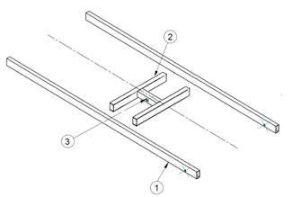
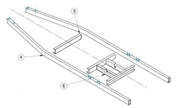
Fig. 12. The frame
made in welding technology: (a) upper frame; (b) lower frame. The beam
numbers on the references correspond to the ordinal numbers in Tab. 3
Table 3 presents a list of materials
needed for the production of car trailer frames made in the welding technology.
Table. 4 presents a breakdown of the welder's labour costs on the assembly line
of car trailers.
Tab.
3
List of materials needed for the
production of frames made in the welding technology
|
No. |
Element |
Dimensions [mm] |
Length [mm] |
Quantity |
Unit price [€/mr] |
Value [€] |
|
|
Upper frame |
|||||
|
1 2 3 |
Rectangular section profile |
80x40x3 |
2520 |
2 |
7.70 |
38.90 |
|
Rectangular section profile |
80x40x4 |
711 |
2 |
8.54 |
12.18 |
|
|
C-profile |
60x40x4 |
260 |
1 |
5.77 |
1.50 |
|
|
Lower frame |
||||||
|
4 |
Rectangular section profile |
100x50x4 |
3600 |
2 |
12.80 |
92.20 |
|
5 |
C-profile |
100x50x3 |
700 |
3 |
9.00 |
18.90 |
|
6 |
C-profile |
88x54x4 |
480 |
2 |
9.82 |
9.40 |
Tab.
4
List of the cost of
the welder's work
|
Weld length [mm] |
Welder rate [€/mm] |
Total costs in € |
|
2904 |
0.032 |
93.00 |
To sum up: the total cost of making
the frames in the welding technology is EUR 266.20.
3.4.3. Riveted frame
Figure 13
shows the upper and lower frames made in the riveting technology. Table 5
presents a list of materials needed for the production of car trailer frames
made in riveting technology.
|
|
|
|
(a) |
(b) |
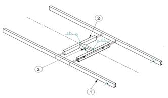
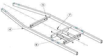
Fig. 13. The frame
made in riveting technology: (a) upper frame; (b) lower frame. The beam numbers
on the references correspond to the ordinal numbers in Tab. 5
Tab.
5
List of materials
needed for the production of frames made in riveting technology
|
No. |
Element |
Dimensions [mm] |
Length [mm] |
Quantity |
Unit price [€/mr] |
Value [€] |
|
|
Upper frame |
|||||
|
1 2 3 |
Rectangular section profile |
80x40x3 |
2520 |
2 |
7.70 |
38.90 |
|
C-section profile |
80x50x3 |
711 |
2 |
Made of sheet metal |
||
|
C-profile |
60x40x4 |
260 |
1 |
5.77 |
1.50 |
|
|
Lower frame |
||||||
|
4 |
Rectangular section profile |
100x50x4 |
3600 |
2 |
12.80 |
9.18 |
|
5 |
C-section profile |
100x50x3 |
700 |
3 |
Made of sheet metal |
|
|
6 |
C-section profile |
100x50x4 |
480 |
2 |
Made of sheet metal |
|
|
7 |
Rivet |
|
|
42 |
0.021 |
0.90 |
The
elements listed in the table marked with the order number 2, 5, 6 will be made
of sheet metal. Dimensions of metal sheets and their prices are given in point
2.1.
Dimensional
analysis shows that half a sheet of each plate can be used to make profiles
intended for the production of one lower and upper frame. So the cost of the
material will be EUR 88.67. The total measurement of the perimeter of
individual profiles cut from 3 and 4 mm thick metal sheets multiplied by the
unit cost of laser cutting allows you to calculate the cost of this
technological operation. Its value is EUR 33.12.
The cost of
bending profiles on the press brake is calculated on the basis of the
employee's hourly rate and is EUR 8.55/h. This cost can be estimated at EUR
4.28.
Table. 6
presents a breakdown of labour costs of a production worker.
Tab. 6
A breakdown of the
labour cost of a production worker
|
Number of riveted connections |
Time of completion and assembly of the connection [min] |
Employee rate [€/h] |
Total costs in € |
|
42 |
10 |
6.40 |
1.10 |
To sum up:
the total cost of riveted frames for one car trailer is EUR 177.80.
Figure 14
shows a chart with a summary of car trailer production costs for individual
assembly technologies.
Fig. 14. Production costs of the trailer in
three production technologies
As can be seen from the summary
presented in Figure 14, the lowest production costs of the car trailer occurs
for the riveting technology. However, in the case of the other two variants,
the costs are at a similar level of about EUR 265.
Finally, it should be added that the
method of protecting the frame against corrosion depends on the assembly
technology. Small elements intended for screwing and riveting can be covered,
for example, with a zinc coating individually, before joining. Each of the
frames, separately upper and lower, should be galvanized in their entirety if
they are welded. This may result in slight variations in electroplating costs,
which are not considered here. In addition, A2 steel rivets should not be used
to connect non-alloy steel components, but if popular blind rivets are used,
their strength is insufficient.
4. CONCLUSIONS
The aim of the research work was to
indicate whether it is possible to change the production technology of the
load-carrying system of a self-dumping car trailer. For this purpose, solid
models of frames made during the process of riveting, bolting, and welding were
made, and a strength analysis was carried out using FEM. The next step was to
prepare technical documentation containing lists of beams of the upper and
lower frames, indicating whether they are standard profiles or made of sheet
metal.
In each of the three versions of the
frames, the highest stress values are generated in the upper frame on the
stringers and in the crossbeams. Another area of maximum stress is the cylinder
pin mounting slots in the upper and lower frames. However, in the case of a
riveted frame, the strength-critical elements are the rivets. The use of
three rivets with a diameter of 6.4 mm in each assembly node causes that the
stresses caused by shear are exceeded in their material. This situation is also
caused by the small wall thickness of the joined profiles, which is 4 mm.
Making the frames in the welding process can be an alternative method of
production in relation to the original frame of the trailer. The implementation
cost is close. It should be noted here that in the case of welded frames, all
beams are made of standard profiles. The need to make beams by laser cutting
from sheet metal and bending on the press brake is eliminated. In the case
of riveted frames, their production cost is the lowest, by about 1/3 compared
to the cost of welded and bolted frames. The cost is low, although it is
necessary to make three beams yourself.
References
1.
Barta D., J. Dižo, M. Blatnický, D. Molnár. “Experimental
research of vibrational properties of a single-axle trailer when crossing an
individual road obstacle”. 2022. Strojnícky
Časopis – Journal of Mechanical Engineering 72(3): 19-26.
2.
De Bernardis M., G. Rini, F. Bottiglione, A.E. Hartavi,
A. Sorniotti. 2023. “On nonlinear model predictive direct yaw moment control
for trailer sway mitigation”. Veh. Syst.
Dyn. 61(2): 445-471. DOI: 10.1080/00423114.2022.2054352.
3.
DIN 7337: 1991. Blind rivets with break
mandrel.
4.
Dižo J., M. Blatnický, R. Melnik, S. Semenov, E.
Mikhailov, J. Kurtulik. 2022. “Static analysis of tipping superstructure of
single-axle tractor trailer”. In: Engineering for rural development, Jelgava,
25.-27.05.2022. DOI: 10.22616/ERDev.2022.21.TF003.
5.
Gnap J., J. Jagelčák, P. Marienka, M. Frančák, M.
Kostrzewski. 2021. “Application of mems sensors for evaluation of the dynamics
for cargo securing on road vehicles”. Sensors
21(8): 2881.
6.
Welding –
definition, types and valuation. Available at:
https://allweld.pl/spawanie-i-spawalnictwo.
7.
Bobrek. Available
at: https://bobrek.pl/.
8.
Manufacturer
of pipes, profiles and steel structures. Available at:
https://www.stalimpex.eu.
9.
Stawex. Available
at: http://www.stawex.com.pl/.
10.
Ibrahim A.M., A.M. Ali, H. Kamel. 2023. ”Design
optimization and production of a small-scale semi-trailer chassis for
testing”. J. Eng. Appl. Sci. 70: 35.
DOI: 10.1186/s44147-023-00201-z.
11.
Jagelčák, J., M. Kiktová, M. Frančák. 2020. ”The
analysis of manoeuvrability of semi-trailer vehicle combination”. Transp. Res. Proc. 44: 176-181.
12.
Kulikowski K., Z. Kamiński. 2019. “Methods for
improving the dynamic properties of the air braking systems of low-speed
agricultural trailers”. Arch. Automot.
Eng. 84(2):
5-22. DOI: 10.14669/AM.VOL84.ART1.
13.
Ladra P., B. Posiadała. 2018. “Strength Analysis of
the Multi-tasking Car Trailer”. In: Rusiński E., D. Pietrusiak (eds).
Proceedings of the 14th International Scientific Conference: Computer Aided
Engineering. CAE 2018. Lecture Notes in
Mechanical Engineering. Springer, Cham. 2019. P. 419-426. DOI: 10.1007/978-3-030-04975-1_49.
14.
Ladra P., B. Posiadała. 2018. “Modeling and strength
analysis of the prototype of the multi-tasking car trailer”. MATEC Web Conf. 157: 01014.
15.
Ladra P., B. Posiadała. 2016. “Modeling and strength
analysis of the specialized car trailer”. In: Proceedings of the 13th International Scientific Conference: 313-321.
16.
Lodwik D., J. Pietrzyk. 2018. “Analysis of the
structure of the frame of a trailer for transport of bales of compressed straw
in the aspect of minimization of materials and energy consumption”. In: 3rd International Conference on Energy and
Environmental Protection, E3S Web
Conf. 46: 00005. DOI: 10.1051/e3sconf/20184600005.
17.
Marienka
P., M. Frančák, J. Jagelčák, F. Synák. 2020. ”Comparison of
braking characteristics of solo vehicle and selected types of vehicle
combinations”. Transp. Res. Proc. 44:
40-46.
18.
Mokričková L., V. Rievaj. 2016. “Position of the
centre of gravity and driveability of the vehicle”. LOGI Sci. J. Transp. Logist. 7: 108-115.
19. Plöchl M.,
P. Lugner. 1999. “ Passenger car and passenger car-trailer – different tasks
for the driver”. JSAE Review 20(4): 543-548. DOI: 10.1016/S0389-4304(99)00036-3.
20.
Sagi R., A. Racotch, D. Wolf. 1973. “Theoretical
considerations in placing the centre of gravity of single-axled trailers”. J. Agric. Eng. Res. 18(2): 159-165.
21.
Schuh G., C. Kelzenberg, J. Wiese. 2019. ”Design
model for the cost calculation of product-service systems in single and small
series production”. Procedia CIRP 84:
296-301. DOI: 10.1016/j.procir.2019.04.216.
22.
Skrúcaný T., J. Vrábel, M. Kendra, P. Kažimír. 2017. ”Impact
of Cargo Distribution on the Vehicle Flatback on Braking Distance in Road
Freight”. In: 18th International
Scietific Conference – LOGI 2017, MATEC
Web Conf. 134: 00054. DOI: 10.1051/matecconf/201713400054.
23. Viano D.C., C.S. Parenteau.
2022. “Significance of tractor-trailer impacts to the rear of light vehicles”.
Traffic Inj. Prev. 23(4):
169-175.
24.
Vrabel J., T. Skrucany, L. Bartuska, J. Koprna. 2019. “Movement
analysis of the semitrailer with the tank-container at hard braking - the
case study”. IOP Conf. Ser. Mater. Sci.
Eng. 710(1): 0120254.
25.
Wang G.L., Y.H. Lu. 2006. “Braking stability analysis
of car-trailer”. Journal of Jiangsu
University 27(2): 130-132.
26.
Figlus Tomasz, Lukasz Kuczyński. 2018. "Selection
of a semi-trailer for the haulage of long oversize loads, taking into account
an analysis of operational damage". In: 11th International Science and Technical Conference Automotive
Safety: 1-5.
27.
Zamecnik J., J. Jagelcak. 2015. “Evaluation of wagon
impact tests by various measuring equipment and influence of impacts on cargo
stability”. Commun. Sci. Lett. Univ.
Zilina 17(4): 21-27. DOI: 10.26552/com.C.2015.4.21-27.
28.
Zhang N.,
J.-H. Wu, T. Li, Z-Q. Zhao, G.-D. Yin. 2021. “Influence of braking
on dynamic stability of car-trailer combinations”. Proceedings of the Institution of Mechanical Engineers, Part D: Journal
of Automobile Engineering 235(2-3): 455-464. DOI: 10.1177/0954407020959895.
29.
Zhang N., G. Yin, T. Mi, X. Li, N. Chen. 2017. ”Analysis
of dynamic stability of car-trailer combinations with nonlinear damper
properties”. Procedia IUTAM 22:
251-258.
Received 29.02.2024; accepted in revised
form 07.04.2024
![]()
Scientific
Journal of Silesian University of Technology. Series Transport is licensed
under a Creative Commons Attribution 4.0 International License