Article citation information:
Mikhailov,
E., Semenov, S., Shvornikova, H., Dižo,
J., Blatnický, M., Droździel,
P., Kravchenko, K. Possibilities
of improving a rail vehicle running safety with independently rotating wheels. Scientific Journal of Silesian University of
Technology. Series Transport. 2022, 115,
93-106. ISSN: 0209-3324. DOI: https://doi.org/10.20858/sjsutst.2022.115.7.
Evgeny MIKHAILOV[1],
Stanislav SEMENOV[2],
Hanna SHVORNIKOVA[3],
Ján DIŽO[4],
Miroslav BLATNICKÝ[5],
Paweł DROŹDZIEL[6],
Kateryna KRAVCHENKO[7]
POSSIBILITIES OF IMPROVING A RAIL VEHICLE RUNNING SAFETY WITH
INDEPENDENTLY ROTATING WHEELS
Summary. This work is
focused on the possible ways of improving the running safety of a railway
vehicle, which uses IRWs (independently rotating
wheels) in a bogie. It discusses the main positive and negative properties
of an application of IRWs for a railway vehicle while
it is running in a curve. There are evaluated running properties of a railway
vehicle in terms of safety for IRWs and a standard
wheelset (SW). It is assumed that a wheelset design with IRWs
will reduce the risk of derailment of a railway vehicle in a curve with a
smaller radius because it will be reached a more favourable distribution of
decisive forces in the wheel/rail contact. A designed wheelset with IRWs differs from other IRWs
designs; in this case, only a flange can rotate independently from a wheel
treat surface about the axis of rotation. Further, this research presents an
analysis of a friction forces distribution of the friction forces in a contact
of a flange and a rail head and a comparison with an SW. The obtained results
allow concluding that it is advisable to use the wheels with the perspective
wheel design (including independently rotating) to reduce the resistance to
movement and improve the running properties of a railway vehicle for safety.
Keywords: rail
vehicle; running safety; independently rotating wheels; mathematical
calculation
1. INTRODUCTION
Research in
the last decades has focused on the design of railway vehicles and their
running properties to improve dynamical properties for running safety [1, 2].
It mainly relates to increasing the running speed of railway vehicles, reducing
the wear of railway wheelsets and rails and other important facts. However, the
factors described above are not only associated with the high speed but, on the
contrary, with the low speed of a railway vehicle as well. The risk of
derailment of a railway vehicle, a shorter lifetime of its wheels and rails, a
higher level of noise and other negative effects also occur while a railway
vehicle runs at lower speed and mainly in curves with smaller radii. In such
cases, a standard wheelset (SW) of a railway vehicle does not sufficiently meet
the demand of the smallest possible angle of attack (it is given by wheelset
guidance, etc.). Therefore, longitudinal slippage, as well as the running
resistance, arise. The use of IRWs instead of SWs in
a bogie for urban railway vehicles (that is. mainly for trams), is one of the
possible ways of reducing the described negative effects [3-9].
When IRWs are mounted on a railway vehicle bogie, wheels rotate
either as a whole (a flange with a wheel tread surface) or as two parts (a
flange rotates independently from a wheel tread surface) about an axis of
rotation. Such a technical solution helps to eliminate slippage in the
longitudinal direction, which results in reducing running resistance when a
railway vehicle runs in curves. Improvements of running behaviours
of a railway vehicle with IRWs are mainly [3]:
- reduce
wagging at high speeds,
- reduce wear of
contact surfaces of a rail and a wheel with a flange,
- improve railway
vehicles behaviours related with running in curved
sections of a railway track, as it practically eliminates of components the
creep forces in the longitudinal direction.
Hence, two
wheels of one IRW pair rotate at various speeds.
Subsequently, this causes minimal values of creep forces in the longitudinal
direction, ensures the moment for controlling the wheelset motion and centres a wheelset in the longitudinal axis of the railway
track. On the contrary, the angle of attack of the wheelsets is being
increased; therefore, the wear of tread surfaces of the wheels and rails also
increase together with the values of the lateral forces. Higher values of the
lateral forces lead to higher values of the derailment quotient, which means a
higher risk of derailment of a railway vehicle.
2. ANALYSIS OF
RECENT RESEARCH AND PUBLICATIONS
Relatively,
many technical solutions attempt to eliminate the disadvantages of using IRWs in bogies. Some technical solutions include the
application of a joint between a wheel and an axle, which has prescribed
certain elastic characteristics. The simplest solution is the mounting of a
wheel with a flexible element (usually rubber-based elements) to an axle [7].
However, IRWs with rubber elements are not suitable
for railway vehicles, which run at higher speeds.
Other
technical designs are based on more complicated systems that require using
specific components to ensure increasing the torsional flexibility of the axle
of a wheelset. The principle of their functionality is that they allow locking
the wheels on an axle when a railway vehicle runs on a straight track section,
and thus, it behaves as a railway vehicle with SWs. However, when a railway
vehicle with this device enters a curve, the device is activated, and it
unlocks the wheels, so they can rotate independently on an axle [9]. Pioneers
of this approach are believed to be specialists from the MBB
Company (Germany). They have developed large studies based on both theoretical
backgrounds and experiments. As a regulator, they have applied a clutch working
with magnetic powder.
One
of the ways of ensuring the optimal interaction of wheels and rails of rail
vehicles (with IRWs) to minimise lateral forces
together with, is the use of a specialized mechatronic system to monitor the
position of a wheelset in the horizontal plane [11-14]. In rail vehicles bogies
with radial guidance of wheelsets, the angles of attack of the wheelsets
regarding a track when it is running in curves are close to zero. Among the
most known bogies with a system ensuring the additional movement of a wheelset
in a bogie are those with [15, 16]:
- a system for a
self-centring wheelset,
- a system allowing a
semi-forced guidance of a wheelset,
- a system allowing a forced
guidance of a wheelset.
The
results of numerous studies [17-25] have shown an increased propensity of rail
vehicles with IRWs to derailment by climbing of the
wheel flange on a rail head. The absence of longitudinal creep forces when the IRW moves on a rail means that the friction forces in the
wheel/rail contact act entirely in the lateral direction. It results in a risk
when the wheel flange can climb on a rail. This risk increases with the
decreasing distance of a flange lifting [19, 22]. Furthermore, the results of
the research [20] show that the value of the longitudinal forces in the contact
of a wheel and a rail directly increases with the value of the Y/Q
ratio. This ratio is called the derailment quotient. Hence, the Nadal
criterion, which characterizes the conditions where the flange can climb to a
rail head, can be softened and this depends on which values the longitudinal
forces reach in the contact of a wheel and a rail. The creep forces in the
longitudinal direction support the redistribution of the friction forces
components in the contact of a wheel and a rail. This decreases the effective
friction coefficient and increases the Y/Q ratio, which is required for the
derailment of a railway vehicle [23].
Research
in this field has demonstrated more or less satisfying results, hence needs
further investigation.
In
comparison with the IRWs described above, this work
is aimed at research relating to the application of IRWs
with the perspective wheel design (PWD). This
technical design is characterized by a rotating wheel flange relative to the
wheel tread surface, which for this work, are IRWs
with traditional wheel design (TWD).
Generally,
during the moving of a wheel on a rail, contact points of the wheel tread
surface and the flange move in a space and they perform a complex spatial
movement with a cycloidal trajectory [24]. In the case of the SW with a TWD
type, parasitic differential slip arises, as between the geometric
parameters of the rolling surfaces of a railway wheel and the kinematic
parameters of movement is certain dissonance [25-29]. Thus, the wear intensity
of surfaces of a railway wheel and a rail is given by the power of the friction
forces. It is more noticeable in the curved sections of a railway track
[30-33]. One way of decreasing consumed energy together with
wear in curves is to lubricate the contact surfaces. However, this does not
adequately solve the problem.
The
main objective of this contribution is to present the possibilities of
improving a railway vehicle’s running properties for safety, which are
equipped by the IRW of the PWD
type.
3. STATEMENT
OF THE MAIN MATERIAL
The distribution of forces,
which are important for the evaluation of the risk of derailment of a railway
vehicle, is shown in Figure 1. It captures the situation when it begins to
climb on a rail head. The individual forces are as follows: R is a general reaction, PZ is a magnitude of forces
in a vertical direction, and YG is a magnitude of forces in a horizontal
direction.
The following formulations
describe the common magnitude of reaction forces in the contact of a flange and
a rail head:
![]() (1)
(1)
![]() (2)
(2)
![]() (3)
(3)
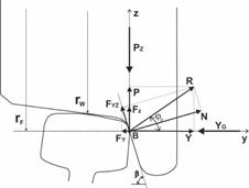

Fig.
1. Distribution of forces in the contact of a flange and a rail head at
the moment of climbing: front view (left), side view (right)
The design of a wheelset with the IRWs PWD type allows the flange to rotate relative to the tread
surface of the wheel in the given coordinate system; it increases the number of
degrees of freedom to the solved mechanical system. Equations of equilibrium of
the forces in the z-axis direction and the moments about the B contact point
are as follows (Figure 1, right):
![]() ,
, ![]() (4)
(4)
Where:
![]() - the sum of the
forces, which act on the wheel in the axis OZ direction,
- the sum of the
forces, which act on the wheel in the axis OZ direction,
![]() - the
sum of the moments of the forces
about the B point.
- the
sum of the moments of the forces
about the B point.
Then:
![]() (5)
(5)
Where:
YZ - the component of a
reaction of the guiding force YG in the vertical direction,
FZ - the component of the
friction force in the contact of the flange and the rail head in the vertical
direction,
PZ - the sum of the forces generated by the
wheel gravity and the weight of a railway vehicle corresponding to the wheel.
The process of derailment of
the wheel starts at the moment, when the wheel surface (with the PDW type) begins to leave the rail head surface (point A). At this moment, the centre of
rotation of the wheel moves to point B
(Figure 1). This sliding movement continues up to the rail head in the OZ axis direction. This is
caused by the component of the reaction YZ in the vertical direction, at which, the force
Y is the guiding force. The value of the YZ force component is
given by the formulation:
![]() (6)
(6)
Herein:
![]() (7)
(7)
The values of the forces,
which are used in formulations 6 and 7, that is, force PZ and YG, are given and they can be changed. Further,
the calculation process requires estimating the force FZ. At the earliest,
there have been analysed properties of the movements of the wheels for the TWD
type of wheel and the PWD type of wheel for a
two-point contact [26-30]. The results of analyses of the TWD type of the
railway wheel reveal that the unambiguous determination of the modulus and the
direction of the vector of the friction force depends on the geometric
characteristics for the contact of the wheel and the rail and the wheel angular
speed. However, the railway wheel of PWD type needs
to determine the two parameters mentioned above the additional parameter,
namely the ratio expressing angular velocity of the tread surface of a wheel
and a flange about their mutual axis of rotation. Then, the following
formulations can be considered:
![]() (8)
(8)
![]() (9)
(9)
![]() (10)
(10)
Index “i”, which
appears in equations 8 to 10 means, for which wheel design are these forces
calculated. The PWD type of a wheel is marked by a
“*”.
Formulations for the
determination of the parameters δ
or δ* are as follows:
 ,
,  (11)
(11)
![]() ,
,  (12)
(12)
where:
![]() ,
,
ψ - is the angle of attack of the considered
wheel,
β - is the angle, which gives the slope of the
flange of a wheel relative to the horizontal plane.
These subsequent
formulations enable the calculation of the component of the friction force for
both TWD and PWD types of wheels in the vertical
direction:
- the
ТWD type of wheel:
![]() (13)
(13)
- the
PWD type of wheel:
![]() (14)
(14)
Next, condition (6) can be
written as:
![]() (15)
(15)
Now, it is possible to
characterize a coefficient of movement stability ![]() of a wheel regarding
derailment:
of a wheel regarding
derailment:
![]() (16)
(16)
where: ![]() .
.
The wheel begins to climb on
the rail head, when the coefficient reaches values lower than 1, that is, ![]() .
.
Figure 2 depicts the
waveform of the calculated values of the ![]() safety coefficient for a TWD
type of wheel and a PWD type of wheel. Curves are
determined for the following parameters: ψ
= 0.015, KW = 1.021 and PZ = 125 kN.
safety coefficient for a TWD
type of wheel and a PWD type of wheel. Curves are
determined for the following parameters: ψ
= 0.015, KW = 1.021 and PZ = 125 kN.
By analysing the graphs shown in Figure 2, we
can observe that the value of the coefficient KS characterizing the margin of stability of the wheels
from derailment, when the flange is climbing at the initial stage of this
process, depending on the guiding force YG magnitude and it is practically the same for
railway wheels of both types. Differences in values of the KS coefficient are determined by the effects of the
considered wheel type on the distribution of individual components of the
friction force. Particularly, the effect of the component of the friction force
in the vertical direction.

Fig.
2. The waveform of the safety coefficient KS
= f(YG): 1
– the TWD of a wheel,
2 – the PWD type of a wheel
In this considered case, the
value of this KS
coefficient gives an idea of whether the flange of a railway wheel can climb to
a rail head.
The criterion of running
safety calculated for the risk of derailment is one of the most important data
for railway vehicle running safety [19, 22, 25]. The
Nadal criterion (usually marked as KN) expresses a standard condition from the
viewpoint of running stability [31]. Based on this criterion, the demand for
running safety given the derailment risk of a railway vehicle must meet the
following condition:
![]() (17)
(17)
where:
KNad - is the normalized Nadal
factor, which reflects the limit of the ratio G/V,
[KN] - is the limit
value for the stability coefficient.
Further:
![]() (18)
(18)
where:
μ - is the friction coefficient of friction
between the flange and the rail head.
G - the horizontal force of pressure of the attacking wheel on
the rail;
β - the angle of inclination of the generatrix of the wheel flange to the horizontal line;
V - the vertical force of pressure of the attacking wheel on the
rail;
The solved task requires
modifying the traditional criterion for the evaluation of railway vehicle
stability.
It is interesting to
determine the friction force magnitude (depicted as FYZ). This force acts
in the plane marked as YOZ. Its value is calculated
following equations 9 and 10 as follows:
 (19)
(19)
Thereafter, the value of the
friction coefficient ![]() is determined by the
formulation:
is determined by the
formulation:
![]() (20)
(20)
There are certain
differences in the values of angles marked as δi and χi
for individual variants of the technical solutions of the designed wheels.
Then, the values of the Nadal criterion are calculated as follows:
- for
a wheelset with the ТWD type:
 (21)
(21)
- for
a wheelset with the PWD type:
 (22)
(22)
In the case of the
requirement to evaluate the derailment criterion depending on the design of a
wheel, the ratio ![]() is quantified. This ratio is
calculated for the same number obtained from the ratio G/V. Figure 3 shows the
dependence of the parameter ΔKN = f(ψ, KW).
is quantified. This ratio is
calculated for the same number obtained from the ratio G/V. Figure 3 shows the
dependence of the parameter ΔKN = f(ψ, KW).
From the graph, it can be seen that there is a
certain range of such operating parameters, for which the
reached Nadal criterion values for the wheel with the PWD
type are lower in comparison with the Nadal criterion values for the wheel with
the ТWD type. This is because the design of the
wheel influences the friction force distribution in contact with the wheel and
the rail.
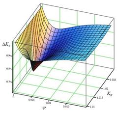
Fig.
3. Dependence graph ΔKN = f(ψ, KW)
Figures below (Figures 4 and 5) depict the
comparison of the results of the moments calculated for the TWD type as well as
the PWD type of a railway wheel for particular
parameters as follows: YG
= 50 kN, KW
= 1.021, PZ = 125 kN, hF
= 0.01 m, rW
= 0.475 m,
μr
= 0.25.
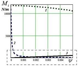
Fig.
4. Graph depicting the dependency of the values of Mi = f(ψ): 1 - MX1 = f(ψ)
(TWD type of wheel), 2 - MX2 = f(ψ)
(PWD type of wheel), 3 - MZ = f(ψ)

Fig.
5. Detail of the graph depicted in Figure 4
As seen from the graphs
depicted in Figures 4 and 5, the value of the moment MZ is higher than the value of the moment MX for a railway wheel with the PWD
type, although the angle of attack is quite small (that is, for the value of ψ > 0.0017 rad or about
0.1°).
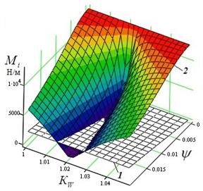
Fig. 6. Dependency
graphs Mi = f(ψ, KW): 1 - MZ = f(ψ, KW), 2 - MZ = f(ψ, KW)
Figure 6 highlights the results of the
calculation of the moment Mi for the given parameters for the PWD type of a railway wheel. It can be recognized that the
described behaviour of the PDW type of a railway
wheel is specific for an obvious range of values KW.
4. CONCLUSION
The research results revealed interesting findings. Practically,
conditions for the beginning of climbing of the wheel flange on a rail head are
the same for IRWs with the TWD type and the IRWs with the PWD type. The Nadal
criterion was used for the calculation of the derailment factor in this work.
This criterion considers the effect of the angle of attack of a wheel as well
as the behaviours of the type of IRW. The reached
results showed that the calculated values of the modified Nadal criterion are a
bit smaller for the PWD type of a wheel in comparison
with the considered criterion for the TWD type of a wheel. This is because the
design of the railway wheel influences the distribution of the friction forces
in contact with the flange and the rail. However, this is not critical for
using the PWD of wheels. Performed analyses have
determined, in this case, that the angle of attack is higher than 1.7∙10-4
rad, the IRW with the PWD
type practically does not roll on a rail. The wheel flange with the PWD type tends to rotate to the opposite side relative to
the direction of the wheel in which it moves. Hence, it seems expedient to
apply railway wheels with the IRW of the PWD type in a bogie of a railway vehicle with IRWs to improve the running properties for safety.
Acknowledgement
This research was supported by the Cultural and
Educational Grant Agency of the Ministry of Education of the Slovak Republic
under project No. KEGA 023ŽU-4/2020: Development of advanced virtual models
for studying and investigating transport means operation characteristics.
References
1.
Zhang Dawei, Peijuan Xu, Daniele Bigoni. 2019.
„Application and comparison of uncertainty quantification methods for
railway vehicle dynamics with random mechanical parameters“. Mechanika 25(6): 455-462. ISSN:
1392-1207
2.
Zhussupov Kenes, Aliya Toktamyssova, Seidulla Abdullayev,
Gabit Bakyt, Manarbek Yessengaliyev. 2018. „Investigation of the stress-strain
state of a wheel flange of the locomotive by the method of finite element
modeling“. Mechanika 24(2):
174-181. ISSN: 1392-1207
3.
Dukkipati Rao V., Swamy S. Narayana, Osman Mohammad O.M.
1992. „Independently rotating wheel systems for railway vehicles - A
state-of-the-art review”. Vehicle
System Dynamics 21(1): 297-330. ISSN: 0042-3114. DOI: https://doi.org/10.1080/00423119208969013.
4.
Liang B., S. Iwnicki. 2007. „An experimental study of
independently rotating wheels for railway vehicles“. In: IEEE International Conference On
Mechatronics And Automation I-V: 2282-2286. August 05-08, Harbin, China.
5.
Zaazaa Khaled E., Brian
Whitten. 2008. „Effect of
independently rotating wheels on the dynamic performance of railroad
vehicles“. In: Рroceedings of
the ASME International Mechanical Engineering Congress and Exposition 2007:
467-477. November 11-15, Seattle, WA, USA.
6.
Nabilah Farhat,
Christopher Ward, Omar Shaebi, David Crosbee, Julian Stow, Ruichen Wang,
Roger Goodall, Martin Whitley. 2020. „Controlling a Rail Vehicle with
Independently-Rotating Wheels“. In: Advances
in Dynamics of Vehicles on Roads and Tracks 1925. Edited by Matthijs Klomp, Fredrik Bruzelius, Jens Nielsen, Angela
Hillemyr. Gothenburg, Sweden: Springer. ISBN: 978-3-030-38077-9. DOI: https://doi.org/10.1007/978-3-030-38077-9.
7.
Bracciali Andrea. 2016. „Railway Wheelsets:
History, Research and Developments“. International
Journal of Railway Technology 5(1): 23-52. ISSN: 2049-5358. DOI: https://doi.org/10.4203/ijrt.5.1.2.
8.
Goodal Roger, Li Hong. 2000. „Solid axle and
independently-rotating railway wheelsets - a control engineering assessment of
stability“. Vehicle System Dynamics
33(1): 57-67. ISSN: 0042-3114. DOI: https://doi.org/10.1076/0042-3114(200001)33:1;1-5;FT057.
9.
Kostrzewski Mariusz, Rafał Melnik. 2017.
„Numerical dynamics study of a rail vehicle with differential
gears“. Procedia Engineering
192: 439-444. ISSN: 1877-7058. DOI: https://doi.org/10.1016/j.proeng.2017.06.076.
10.
Bracciali Andrea, Megna Gianluca. 2016. „Contact
mechanics issues of a vehicle equipped with partially independently rotating
wheelsets“. Wear 366-367:
233-240. ISSN: 0043-1648. DOI: https://doi.org/10.1016/j.wear.2016.03.037.
11.
Perez J., J.M. Busturia, Mei Tan Xue, Vinolas Jordi. 2004. „Combined active steering and traction for mechatronic
bogie vehicles with independently rotating wheels”. In: 2nd IFAC
Conference on Mechatronic Systems: 207-217. IFAC.
December 09-11, Berkeley, CA, USA. ISSN: 1367-5788. DOI:
https://doi.org/10.1016/j.arcontrol.2004.02.004.
12.
Kapitsa Mikhail, Evgeni Mikhailov, Sergii Kliuiev,
Stanislav Semenov, Maksim Kovtanets. 2019. „Study of rail vehicles
movement characteristics improvement in curves using fuzzy logic mechatronic
systems“. MATEC Web of Conferences
294: 03019. ISSN: 2261-236X. DOI: https://doi.org/10.1051/matecconf/201929403019.
13.
Mikhailov Evgeny, Juraj Gerlici, Sergey Kliuiev,
Stanislav Semenov, Tomas Lack, Kateryna Kravchenko. 2019. „Mechatronic system
of control position of wheel pairs by railway vehicles in the rail track“.
AIP Conference Proceedings 2198:
020009. ISSN: 0094-243X. DOI: https://doi.org/10.1063/1.5140870.
14.
Fu Bin, Rocco Libero Giossi, Rickard Persson, Sebastian
Stichel, Stefano Bruni, Roger Goodall. 2020. „Active suspension in
railway vehicles: A literature survey“. Railway Engineering Science 28(1): 3-35. ISSN: 2662-4753. DOI: https://doi.org/10.1007/s40534-020-00207-w.
15.
Dvorak Zdeněk, Bohuš Leitner, Ladislav Novak.
2015. „Software support for railway traffic simulation under restricted
conditions of the rail section“. In: Proceedings
of the 9th International Scientific Conference TRANSBALTICA 2015: 245-255.
Vilnius Gediminas Technical University. May 07-08, Vilnius, Lithuania. ISSN:
1877-7058. DOI: https://doi.org/10.1016/j.proeng.2016.01.066.
16.
Upadhyay R. 2000. „Reduced wear wheels and
railway“. International Railway
Journal 7: 33-34.
17.
Mašek Jaroslav, Martin Kendra, Sanjin
Milinković, Slavko Vesković, Dalibor Barta. 2015. „Proposal and
application of methodology of revitalisation of regional railway track in
Slovakia and Serbia. Part 1: theoretical approach and proposal of methodology
for revitalisation of regional railways“. Transport Problems 10: 85-95. ISSN: 1896-0596. DOI: https://doi.org/10.21307/tp-2015-064.
18.
Leitner Bohuš, Lenka Môcová, Martin
Hromada. 2017. „A new approach to identification of critical elements in
railway infrastructure“. In: Proceedings
of the 10th International Scientific Conference on Transportation Science and
Technology TRANSBALTICA 2017: 143-149. Vilnius Gediminas Technical
University. May 04-05, Vilnius, Lithuania. ISSN: 1877-7058. DOI: https://doi.org/10.1016/j.proeng.2017.04.360.
19.
Wilson Nicholas, Xinggao Shu, Ken Kramp. 2004.
„Effects of independently rolling wheels on flange climb derailment“.
In: ASME 2004 International Mechanical
Engineering Congress and Exposition:
IMECE2004: 21-27. November 13-19, Anahaim, California, USA. ISBN:
0-74918-4712-83. DOI: https://doi.org/10.1115/IMECE2004-60293.
20.
Opala Michał. 2016. „Study of the derailment
safety index Y/Q of the low-floor tram bogies with different types of guidance
of independently rotating wheels“. Archives
of Transport 38(2): 39-47. ISSN: 0866-9546. DOI: https://doi.org/10.5604/08669546.1218792.
21.
Shen G., J. Zhou, L. Ren. 2006. „Enhancing the
resistance to derailment and side-wear for a tramway vehicle with independently
rotating wheels“. Vehicle System Dynamics
44(1): 641-651. ISSN: 0042-3114. DOI: https://doi.org/10.1080/00423110600882738.
22.
Wilson Nicholas, Huimin Wu, Adam Klopp, Alexander Keylin.
2019. „Railway vehicle derailment and prevention“. In: Handbook of Railway Vehicle Dynamics
913. Edited by Simon Iwnicki, Maksym Spiryagin, Colin Cole, Tim McSweeney.
Plce: CRC Press Boca Raton. ISBN: 978-0429-4693-98. DOI: https://doi.org/10.1201/9780429469398.
23.
Xu Jingmang, Jian Wang, Ping Wang, Jiayin Chen, Yuan Gao,
Rong Chen, Kaize Xie. 2020. „Study on the derailment behaviour of a
railway wheelset with solid axles in a railway turnout“, Vehicle System Dynamics, 58(1): 123-143.
ISSN: 0042-3114. DOI: https://doi.org/10.1080/00423114.2019.1566558.
24.
Mikhailov Evgeny, Stanislav Semenov, Svitlana Sapronova,
Viktor Tkachenko. 2020. „On the issue of wheel flange sliding along the
rail“. In: 11th Transbaltica
International Scientific Conference (TRANSBALTICA) - Transportation Science and
Technology: 377-385. Vilnius Gediminas Technical University. May 2-3,
Vilnius, Lithuania. ISBN: 978-3-030-38665-8. DOI: https://doi.org/10.1007/978-3-030-38666-5_40.
25.
Dukkipati Rao V. 2000. Vehicle Dynamics. Narosa Publishing House 591. ISBN: 0-8493-0976-X.
26.
Mikhailov Evgeny, Stanislav Semenov, Viktor Tkachenko,
Svitlana Sapronova. 2018. „Reduction of kinematic resistance to movement
of the railway vehicles“. MATEC Web
of Conferences 235: 00033. ISSN: 2261-236X. DOI: https://doi.org/10.1051/matecconf/201823500033.
27.
Mikhailov Evgeny, Stanislav Semenov, Ján
Dižo, Kateryna Kravchenko. 2019. „Research of possibilities of
reducing the driving resistance of a railway vehicle by means of the wheel
construction improvement“. In: 13th
International Scientific Conference on Sustainable, Modern and Safe Transport
TRANSCOM 2019: 831-838. University of Žilina. May 29-31, Nový
Smokovec, Slovak Republic. ISSN: 2352-1457. DOI: https://doi.org/10.1016/j.trpro.2019.07.117.
28.
Lack Tomáš, Juraj Gerlici. 2017.
„Integration methods for rail vehicle ride dynamics solution
assessment“. In: XXIII Konference s
mezinarodni ucasti: Soucasne problemy v kolejovych vozidlech/ 23rd Conference:
Current Problems in Rail Vehicles 2017: 217-234. Univerzita Pardubice.
September 20-22. Ceska Trebova, Czech Republic. ISBN: 978-80-7560-085-1.
29.
Kurčík Pavol, Juraj Gerlici,
Tomáš Lack, Andrej Suchánek, Jozef Harušinec. 2019.
„Innovative solution for test equipment for the experimental
investigation of friction properties of brake components of brake
systems“. In: 13th International
Scientific Conference on Sustainable, Modern and Safe Transport TRANSCOM 2019:
759-766. University of Žilina. May 29-31, Nový Smokovec, Slovakia. ISSN:
2352-1465. DOI: https://doi.org/10.1016/j.trpro.2019.07.107.
30.
Lack Tomáš, Juraj Gerlici, Pavol
Šťastniak. 2019. „Wheelset/rail geometric characteristics and
contact forces assessment with regard to angle of attack“. MATEC Web of Conferences 254. ISSN:
2261-236X. DOI: https://doi.org/10.1051/matecconf/201925401014.
31.
Nadal Joseph. 1908. Locomotives
a Vapeur, Collection Encyclopedie Scientifique, Biblioteque de Mecanique
Appliquee et Genie. Vol. 186. Paris.
32.
Gerlici Juraj, Rostyslav Domin, Ganna Cherniak, Tomas
Lack. 2017. „Calculated estimation of railway wheels equivalent conicity
influence on critical speed of railway passenger car“. In: XXII Slovak-Polish Scientific Conference on
Machine Modelling and Simlations MMS 2017. University of Zilina, Zilina,
Slovak Republic. 05-08 September 2017, Sklene Teplice, Slovak Republic.
33.
Lack Tomas, Juraj Gerlici. 2017. „The assessment of
the intergration methods for the rail vehicle ride dynamics solution“. In:
XXII Slovak-Polish Scientific Conference
on Machine Modelling and Simlations MMS 2017. University of Zilina, Zilina,
Slovak Republic. 05-08 September 2017, Sklene Teplice, Slovak Republic.
Received 14.01.2022; accepted in
revised form 06.03.2022
![]()
Scientific Journal of Silesian University of Technology. Series
Transport is licensed under a Creative Commons Attribution 4.0
International License