Article citation information:
Manafov,
E., Isgandarov, I., Huseynov,
F. Investigating the protection
system of electric motors based on its main working parameters. Scientific Journal of Silesian University of
Technology. Series Transport. 2022, 115,
63-74. ISSN: 0209-3324. DOI: https://doi.org/10.20858/sjsutst.2022.115.5.
Elshan
MANAFOV[1],
Islam ISGANDAROV[2],
Farid HUSEYNOV[3]
INVESTIGATING THE PROTECTION SYSTEM OF ELECTRIC MOTORS BASED ON ITS MAIN
WORKING PARAMETERS
Summary. This research
was devoted to the creation of a protection system for electric motors used in
industry and transport, based on modern and traditional sensors. In the course
of operation, the malfunctions of electric motors have been investigated and it
was found that the accident modes occur mainly due to exceeding the permissible
values of the current, voltage and temperature parameters. Modern sensors of
current, voltage, and temperature have been compared and the most effective
ones were selected for use in electric motors. Based on reasoning from these
sensors, a protection system for a low-power electric motor has been developed
in the laboratory. In addition, in the Multisim application software package, a
simulation of the operation of the protection system at different voltage and
current values was performed, and a circuit of the sensor control unit and the
power source for powering the protection system was constructed. It has been
proposed to apply such a multi-parametric complex protection system for
electric motors, especially in transport.
Keywords: electric
motor, short circuit, overload, current sensors, voltage sensors,
temperature sensors, relay control, protection system
1. INTRODUCTION
In industry,
transport and various fields of technique, AC (asynchronous, synchronous) and
DC current machines are used. Currently, it is used more than asynchronous
machines that function in motor mode.
Regarding
the development of static converters, the capabilities of induction motors have
significantly increased. Thus, the possibilities of using these motors in
electric transport are considered more effective. In modern electric vehicles,
the short-circuit rotor asynchronous motor is mainly used as an electric motor.
As in all
electrical machines, there is always a high probability of occurrence of
abnormal and failure regimes and damages caused to induction motors. Therefore,
the working process and operating parameters of induction motors, especially in
railway transport, operating in difficult working conditions should be
constantly monitored.
One of the
most important issues in increasing the efficiency and durability of the power
supply system of vehicles is to provide reliable and accurate control of its
electrical parameters and optimal protection against voltage, current and other
parameters in case of accident operation.
From this
research, it has been identified that the application of modern electronic
sensors to control the technical condition of electric motors can provide a
more reliable mode of operation.
It is known
that the increase in load for one reason or the other during the use of
electrical equipment results in the failure of the device, and at best, damage
to the elements of the electrical circuit of the device. Faults of electrical
origin occur as a result of the effects of short-circuit currents, electric
arcs and sparks, reduced insulation resistance as well as other causes. This
shortcoming requires more cost and workers. In recent years, significant
research has been conducted to develop new methods required to monitor the
technical condition of electric motors, overcoming the shortcomings of
traditional methods. The incidence of motor failures or abnormal modes
increases with the complexity of its operating mode; therefore, it is essential
to develop more sensitive and modern protection systems based on the results of
additional failures and the results obtained.
Furthermore,
only the temperature parameter is used to conduct diagnostic monitoring of
traction electric motors - produced by some leading companies in the world -
operating in railway transport. The results of this research show that the
temperature parameter alone does not provide complete and perfect information covering
the technical condition of the motors and several parameters are required to be
added to these parameters in a row to obtain more accurate results. Hence,
complex diagnostic monitoring of electric motor and the creation of
multi-parameter protection systems based on it is actual [1-5].
2. STATEMENT OF THE PROBLEM AND SELECTION OF
SENSORS FOR A MULTI-PARAMETER PROTECTION SYSTEM
The
technical condition of electrical equipment is carried out primarily by
checking the level of reliability and parameters. It is possible to create more
reliable and sensitive protection systems from the information obtained from
the diagnostic monitoring of the technical condition.
To
ensure more stable working conditions, the reserve and reliability indicators
in the motors need to be considered. Suppose
two identical motors are used as a backup in a system. If one of them fails,
the other motor will run at full system load.
Suppose
two identical motors are used as a backup in a system. If one of them fails,
the other motor will run at full system load. The breakdown intensities of the
motors are the same and constant, l= l1 =l2 = 0,0005 1/s. In this
case, it is demanded to identify the exponential law of the probability of
proper operation of the motor at t = 400 hours.
Since the
motors are of the same type, the probability of a malfunction is as follows:
![]() (1)
(1)
According
to the data, the average operating time of the system is calculated as follows:
![]() (2)
(2)
To
increase the probability of proper operation of the electric motor, it is
necessary to ensure its protection against jumps and possible accidents during
the transition process.
Acute
voltage fluctuations, current overloads, short circuits, temperature changes,
etc. in such cases, the establishment and application of a multi-parameter
protection system to prevent equipment, source and load failures are of
particular importance.
During
the operation of electric motors, non-standard and possible accident cases can
be divided into the groups stated below:
• Abnormal
and accident modes occurring in the network (voltage above or below the nominal
value, frequency change, etc.)
• Non-standard currents and accidents
(inter-phase short-circuits in three-phase motors, breakage in stator or rotor
windings, leakage of insulation due to temperature rise caused by overload or
short-circuit currents, etc.)
Special protection devices are developed and applied to protect motors
from damage in unacceptable and accident modes. As it is known, a short-term decrease in voltage leads to a
decrease in the torque of electric motors used in transport. After the voltage
is restored, the motor restores its torque and returns to the nominal operating
mode. In this case, the value of the current required by the motor increases
sharply, which, in turn, can lead to the activation of the protection. The
setting parameters of the protection installed in the electric motor should be
selected so that the protection does not start and turn on the motor circuit
when the short-term voltage drops. For this, special attention should be given
to the selectivity of the security system.
In addition to the current and voltage parameters, one of the other main
parameters subject to protection is the operating temperature of the windings.
It is unacceptable to increase the temperature in the windings. If the
operating temperature of the motor windings exceeds the +10oC heat limit for any period of time, the
insulation of the stator and rotor windings is reduced by half the service
life.
It
is known that there are plenty of sensors based on various physical effects
that control the values of current and voltage: resistive, inductive and
capacitive sensors based on Ohm's law; transformer sensors based on Faraday's
electromagnetic induction law; voltage and current sensors based on the
Holl’s effect, and traditional voltage and current sensors based on other
effects [1, 6, 7].
At
the same time, there are modern sensors based on the application of Rogovsky
winding, electro-optical and magnetic-optical effects intended for non-contact
measurement of high voltages and currents.
Resistors,
transformers and Holl-effect sensors are mainly used to measure the electrical
parameters of modern locomotives used in railway transport.
Resistive
sensors are simple and economical, the principle of operation is based on the
direct proportion of the voltage across the reference resistor connected in
series with the load in the current circuit (Ohm's law), which can be used to
measure direct and alternating currents.
The
external appearance and connection diagram of different types of widely used
current sensors are shown in Figure 1, and the constructive and principle
diagram of the voltage sensors are shown in Figure 2.
a)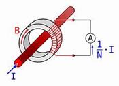
 b)
b)
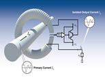
Fig. 1. Constructive and principle scheme
of current sensors:
a) Current transformer; b) Rogowski winding
In
the laboratory, a current transformer was used to control the current value in
the protection system designed for a low-power asynchronous motor. In
high-power motors, the introduction of the Ragowsky windings is considered to
be more promising than the current sensors [8].
Voltage
sensors based
on electrical, electromagnetic, electromechanical, electro-thermal,
electro-optical and other similar physical effects are widely used in
theoretical and practical research.
The
measurement procedure, which is the selection of the appropriate type of sensors,
is determined by the
type and level of voltage. It is important to amplify the signals to record low
voltages in the measurement circuit and reduce the received signals to an
acceptable level at high voltages [9-11].
Voltage
dividers (resistive, capacitive and inductive), voltage transformers,
electronic voltage sensors, etc. are generally used as voltage sensors (Figure 2).
The
use of voltage transformers for measuring high voltages is considered more
expedient.
A resistive divider was used to control the
voltage value in the protection system designed for the low-power electric
motor. The resistive divider is considered simpler and technically more
economical.
Voltage
transformers are often used as voltage sensors in high-power motors. Due to the
large dimensions of voltage transformers, it is more expedient to use a
resistive shunt and a resistive divider as voltage sensors, where possible [12,
13].
a)
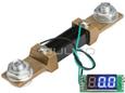 b)
b)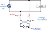
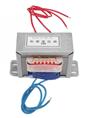
Fig. 2. Constructive and principle scheme of
voltage sensors:
a) resistive shunt; b) voltage transformer
Several
methods are used to measure temperature. These include fiber-optic temperature
sensors, electrical resistance thermometers, thermographic methods,
thermocouple-based temperature sensors, etc. (Figure 3).
As
a contact temperature sensor for determining the temperature value in
high-powered motors, the thermocouple is considered the most suitable.
The
main advantage of a thermocouple-based module sensor is the transmission of a
signal with a direct relay output. Based on the signal received from the
sensor, it is possible to both protect the motor and perform diagnostic
analysis of the recorded data, as well as set up special alarm systems by displaying
the data on special displays. Thanks to this, it is possible to ensure a more
reliable and stable operation of the motor.
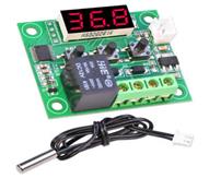
Fig. 3. Constructive and principle scheme
of temperature sensor
Experiments were carried out on the electric motor
according to the three important parameters mentioned above, and a protection
system based on automatic control with relay output was installed. The
operation of the relay is determined by the electrical signal received from the
sensors. Based on the
electrical signals, in any abnormal and accident situation, the relay motor controlled by the protection system is
disconnected from the mains. MLE00137 of type relay was used to protect the
motor (Figure 4).

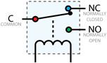
Fig. 4. MLE00137 type protection relay
This
type of relay is distinguished by its compactness, large process switching
capabilities, start-up speed, etc. This relay is able to provide normal
operation when the supply voltage of the working winding is in the range of
6-15 V.
3. MAGNETIC FIELD MEASUREMENT AND OUTPUT SIGNAL ANALYSIS
In
laboratory conditions, an experimental stand built upon a low powerful motor
was developed to simulate malfunctions that may occur in motors and control the
changes occurring in electrical parameters.
One of the most modern
and promising methods intended for diagnosing motor malfunctions and building a
protection-warning system based on this is the measurement and spectral
analysis of the magnetic field.
The results of the analysis show that the defects
and malfunctions in the electric motor have a significant effect on the
spectrum of the electromagnetic field generated outside it. By continuously
monitoring the magnetic aura of the motor in working conditions, it is possible
to determine the change of some parameters and create special protection and
warning systems based on the results obtained. For example, overload, increase
and decrease of voltage, change of current frequency, etc.
In
research, the use of a Hall sensor as a sensor to allow non-contact diagnostics
without interfering with motor design is preferred. Thus, this sensor can be
considered one of the most informative sensors allowing accessing the condition
of the motor by monitoring the electromagnetic spectrum.
In experimental research, the use of the KY-024 Hall sensor, which is less sensitive to external influences, was
preferred. The connection scheme and design structure of these types of sensor
is given in Figure 5.
The recorded oscillograms of the magnetic field
change in different modes of the electric motor studied using the KY-024 sensor
are given in Figure 6.
As seen
from the analysis of the oscillograms, in normal, failures or defects, overload
and other conditions, the magnetic field around the electric motor changes with
a big difference. Thus, based on the recorded data, it is possible to create a
modern protection-warning system by diagnosing the motor while at the same time
analyzing the signals at the output of the sensor.
4. MODELING OF THE MULTI-PARAMETER PROTECTION SYSTEM
In
reality, the development and implementation of a working version of the system
that can perform the above functions is accompanied by many technical problems.
Therefore, since modern applications are more accessible for individual and
complex simulation of functions, it is more advantageous to develop an
imitation model of the system through these programs. This, in turn, allows the
creation of a working model based on an imitation model of the system in
research and production facilities, which allows one to design a real prototype
of the system. In our research, based on the Multisim program, an imitation
model of the device was developed, protecting against short circuits, overloads,
as well as drops in voltage and overvoltage in the phase of the motor powered
by an electric power source.
Relay
control is applied at both high and low voltage limits at specified values. In
the Multisim program, the protection circuits are built and modeled according
to the voltage limit. Schematics of protection activation at normal, high and
low voltage values are shown in Figures 7, 8 and 9. The green LED turning on
indicates that the voltage is within the normal range. While, in abnormal
modes, the red LED turning on indicates that the mains voltage has exceeded the
allowable limit.

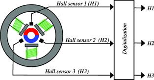
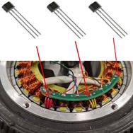
Fig. 5. Traditional connection scheme and constructive descriptions
of the Hall sensor
a)  b)
b) 
Fig. 6. Oscillograms of the motor
magnetic field: a) in normal operation; b) in overload
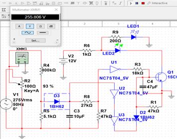
Fig. 7. Electrical circuit of the protection device
at the range of
normal operating voltages (168-260 V)
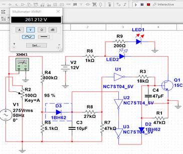
Fig. 8. Electrical circuit of
the protection device at the value of
the voltage above the nominal (Uin > 260 V)
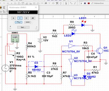
Fig. 9. Electrical circuit of the protection device at a voltage
below the nominal value (Uin <168 V)
The current protection ensures the opening of the
motor from the food source by activating the relay at the limits of the current
above the specified values. A resistive shunt-based protection circuit was used
to simulate current protection in Multisim, and the current variation in the
intended range was simulated by applying an adjustable voltage to the input of
the circuit. The simulation results for the current performed in Multisim are
given in Figures 10 and 11.

Fig. 10. Electrical circuit of the protection device at the nominal
value of current
The
rated motor current is 0,55 A at 220 V. In our case, the critical value of
overloading, that is, the minimum value of the current required for the
protection of operation, is 0,9 A.
Built on the logic elements of the protection
system, a second transformless unit was developed to provide the nominal 5 and
9 V supply voltages required to power the electronic control unit for voltage
limits, transistor control unit for current limits, temperature protection unit
and output relay unit. An autotransformer was used to obtain a controlled
voltage value in laboratory conditions.
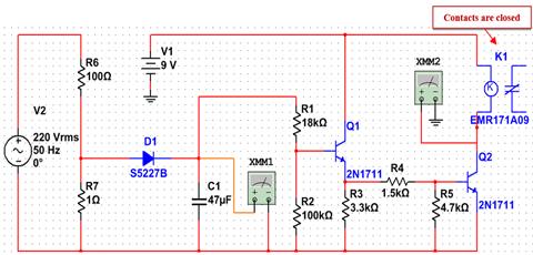
Fig. 11. Electrical circuit of the protection
device during accident operation
(short circuit or allowable value overload)
As mentioned, the second power supply of the unit
is for the power supply of sensors of the voltage, current and temperature also
of the control and protection system. Based on the transformerless power supply
circuit for the power supply of the protection system, the input voltage is 170
– 275 V, the output voltage is 5,1 V, the relay circuit is 7,5 – 12
V, and the total current required by the parametric stabilized power supply is
40-65 mA. Since there is no autotransformer in the Multisim software base, the regulated voltage is supplied to the
circuit via a potentiometer.
For sufficient load capacity of the power supply,
it is possible to use a transistor in the output circuit of the stabilizer as
an amplifier. Since the
base-emitter junction of the transistor has a voltage drop of 0,7 – 0,8
V, a stabilitron with a stabilization voltage of 5,6 – 5,7 V should be
selected to provide 5 V at the output. For the selected stabilitron to operate
in stabilization mode, its current in the range Ist = 3 – 50
mA, as well as the current of the base circuit and stabilitron together can be
selected 10 - 15 mA, given that the rated voltage of the transistor is higher
than 50 and the current at the output of the transistor is less than 100
– 200 mA.
The type of relay designed to replace the power
chains of the selected relays and powerful analog motors can normally operate
at wide voltages (in this case, 7 – 15 V), thus, stabilization is not
required for the relay power circuit. If necessary, the same stabilization
scheme can be applied.
A protection
system based on the relay control was installed and experiments were performed
on the motor to control the temperature parameter. The normal temperature of
the motor windings is identified using the insulation class. Traction electric
motors operated in most modern locomotives used in railway transport are
equipped with C-class insulation (200![]() C and above).
C and above).
 (3)
(3)
·
![]() –
operating temperature of the protection system;
–
operating temperature of the protection system;
·
![]() –
normal motor operating temperature;
–
normal motor operating temperature;
·
![]() –
reconnection temperature;
–
reconnection temperature;
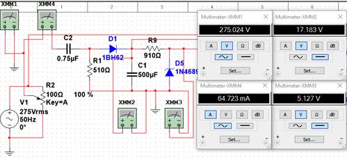
Fig. 12. Electrical circuit of the second power supply of the
protection device
To connect the
protection system (opening the motor) in the motor, which is the object of
study, the temperature of the windings should reach ![]() . These temperature values were conditionally taken
for the experiments. To restore the operation mode of the motor started through
protection, the temperature of the windings must be conditionally lowered to
the reconnection temperature value
. These temperature values were conditionally taken
for the experiments. To restore the operation mode of the motor started through
protection, the temperature of the windings must be conditionally lowered to
the reconnection temperature value ![]() . When the winding temperature cools down to normal
operating temperature (that is, reconnection temperature), the relay restarts
the motor.
. When the winding temperature cools down to normal
operating temperature (that is, reconnection temperature), the relay restarts
the motor.
A
modular thermocouple was used to determine the temperature of the motor
windings. The input of the module is supplied with a constant supply voltage of
9V. The output terminals are similarly connected to the motor and relay. The
thermocouple transmits the signal to the module, where it compares the opening
temperature with the normal temperature and sends a pulse to the relay. The
relay turns on the motor following the received impulse or restarts the motor
with protection.
5. CONCLUSION
Thus, in this research, the faults of the electric motor were
investigated and it was determined that the accident modes occur mainly due to exceeding the permissible values of current,
voltage and temperature parameters. Further, modern current, voltage, and
temperature sensors were
compared and those with the best performance for use in electric motors were
selected. According to the mentioned main parameters, the main control and
power supply blocks of the protection system were analyzed in the Multisim
application program and a model of the system providing complex protection
in the laboratory was practically established.
Based on theoretical and practical research, it can be assumed that it
is possible to show the warning signals on the appropriate display by
protecting the temperature, voltage and current of electric motors used in
transportation and industry and transmitting also the results sent to the relay
control circuit and the central control station.
Having applied the modern sensors we offer, it is possible to ensure a
stable operating mode of electric motors assisted by a complete multi-parameter
protection system.
References
1.
Ferreira Fernando
J.T.E., André M. Silva, Aníbal T. de Almeida. 2018.
“Single-Phasing Protection of Line-Operated Motors of Different
Efficiency Classes”. IEEE
Transactions on Industry 54(3).
2.
Karpavičius
Paulius, Vytautas Ostaševičius, Vytautas Jūrėnas, Jolantas
Baskutienė. 2017. „Self-powered wireless sensor system application
for cutting process control”. Mechanika
23(3): 456-461.
3.
Kozłowski E., K. Antosz, D.
Mazurkiewicz, J. Sęp, T. Żabiński. 2021. „Integrating advanced measurement and signal processing for
reliability decision-making”. Eksploatacja
i Niezawodnosc – Maintenance and Reliability 23(4): 777-787.
4.
Mazurkiewicz D.
2014. „Computer-aided maintenance and reliability management systems for
conveyor belts”. Eksploatacja i Niezawodnosc – Maintenance and
Reliability 16(3): 377-382.
5.
Vaičekauskis M.,
R. Gaidys, V. Ostaševičius. 2013. „Influence of boundary
conditions on the vibration modes of the smart turning tool”. Mechanika 3: 296-300.
6.
Dickinson R., S.
Milano. 2002. “Izolated Open Loop Current Sensing Using Hall Effect
Techn”. In: Optimized Magnetic Circuit. Allegro
MicroSystems, Inc.C.NH, USA. P. 1-12.
7.
Jianghua Feng,
Junfeng Xu, Wu Liao, Yong Liu. 2017. “Review on the Traction System
Sensor Technology of a Rail Transit Train”. Sensors 17(6): 13-26.
8.
Данилов А.Б. 2004.
“Современные
промышленные
датчики
тока”. Современная
электроника
10: 26-28. [In Russian: Danilov A.B.
“Modern industrial current sensors”. Modern electronics].
9.
Bayrak M. 2002.
“A New Digital Relay for Generator Protection Against Asymmetrical
Faults”. IEEE Trans. On Power
Delivery 17(1): 54-59.
10. Jose E.D., T.B. Roy, C. Chai, L. Yu. 1995.
“Stall Protection of Large Induction Motors”. IEEE Transactions on Industry Applications 31(5): 1159-1166.
11. Novak T., A.L. Morley, C.T. Frederick. 1988.
“Sensitive Ground-Fault Relaying”. IEEE Transactions on Industry Applications 24(5): 853-861.
12. Paoletti G.J., A. Rose. 1989. “Improving
Existing Motor Protection for Medium Voltage Motors”. IEEE Transactions on Industry Applications
25(3): 456-464.
13. Zocholl S.E. 1989. “Integrated and Protective
Relay Systems”. IEEE Transactions
on Industry Applications 25(5): 889-893.
Received 07.01.2022; accepted in
revised form 03.03.2022
![]()
Scientific Journal of Silesian University of Technology. Series
Transport is licensed under a Creative Commons Attribution 4.0
International License