Article citation information:
Krasuski, K., Ciećko,
A., Wierzbicki, D. Accuracy analysis of aircraft positioning using
GPS dual receivers in aerial navigation. Scientific
Journal of Silesian University of Technology. Series Transport. 2022, 115, 23-34. ISSN: 0209-3324. DOI: https://doi.org/10.20858/sjsutst.2022.115.2.
Kamil KRASUSKI[1], Adam CIEĆKO[2], Damian WIERZBICKI[3]
ACCURACY ANALYSIS OF AIRCRAFT POSITIONING USING GPS DUAL RECEIVERS IN
AERIAL NAVIGATION
Summary. This study
presents a modified algorithm to determine the accuracy of GPS positioning in
aerial navigation. To achieve this, a mixed model with measurement weights was
used to determine the resultant value of accuracy of aerial vehicle
positioning. The measurement weights were calculated as a function of the
number of GPS tracking satellites. The calculations were performed on actual
GPS measurement data recorded by two onboard GNSS receivers installed onboard a
Cessna 172 aircraft. The flight test was conducted around the military airport
in Dęblin. The conducted analyses demonstrated that the developed
algorithm improved the accuracy of GPS positioning from 62 to 91% for
horizontal coordinates and between 16-83% for the vertical component of the
aerial vehicle position in the BLh ellipsoidal frame. The obtained test results
show that the developed method improves the accuracy of aircraft position and
could be applied in aerial navigation.
Keywords: GPS,
accuracy, receiver, position errors
1. INTRODUCTION
The GNSS satellite technology already enables
precise satellite positioning with the use of 4 global GNSS navigation systems
in aerial navigation. These systems include the American GPS, the Russian GLONASS,
the European Galileo, and the Chinese BeiDou system [1]. However, following
ICAO recommendations [2], currently, only the GPS and GLONASS systems are
certified for aviation. The technical specifications, operation, and
implementation of the GPS and GLONASS systems have been described in detail in
Appendix No. 10 of the Chicago Convention. One of the important elements of
ICAO recommendations is the technical standards concerning the quality
requirements for GNSS positioning in aerial navigation. This refers in
particular to the determination of the accuracy, continuity, availability, and
integrity of GNSS parameters in aviation [3]. The most important quality
parameter of the GNSS satellite positioning for aerial navigation is accuracy.
This parameter defines the difference between the determined coordinates of the
aerial vehicle and the reference position of the flight [4]. Thus, accuracy is
the essential parameter in using the GNSS satellite technique in aerial
navigation.
2. SCIENTIFIC
KNOWLEDGE ANALYSIS
Research
on the GNSS satellite technology in aviation has been conducted in Poland and
internationally since the 1990s. However, most of the analyses concerned the
application of autonomous positioning methods, especially the SPP code
positioning method [5]. As far as international aviation experiments are
concerned, they usually employed the SPP method with the use of the GPS or
GPS/GLONASS systems [6, 7]. In these cases, the position errors were determined
and calculated for the reference trajectory of flight that was determined with
the RTK-OTF differential technique. One very interesting solution used in
aviation experiments globally was the application of the products of IGS
geodesic services in the SPP method, which was described in studies [8-12]. Thus,
aviation experiments applied mainly the SP3 precise ephemeris, precise CLK
clocks, and the IONEX, DCB, or ANTEX formats. The main objective of this
research was to improve the accuracy of autonomous GPS positioning in aerial
navigation through the reduction or the application of new models of systematic
errors in the SPP code method. On the other hand, aviation research conducted
in Poland focused mainly on the wide testing of various GNSS receivers in
aerial navigation [13], to determine the actual accuracy of positioning of
aerial vehicles. The analyses were conducted both in real-time and in the
post-processing mode [14]. In these studies, the resulting coordinates of an
aerial vehicle obtained with the SPP method were compared with the SBAS/EGNOS
method, the differential code method DGPS or the phase differential technique
RTK-OTF [13, 15].
The
analysis of the state of knowledge leads to the following conclusions:
-
Numerous aviation tests were conducted to determine
the accuracy of aircraft positioning using the SPP code method;
-
Tests were conducted both in real-time and in the
post-processing mode, using various classes of GNSS satellite receivers;
-
The conducted research demonstrates the existence of a
problem, which is the low positioning accuracy when the SPP code method is
used;
-
Further flight tests should be conducted using the
GNSS satellite technique, particularly the SPP code method.
-
This allows us to conclude that:
-
It is necessary to develop new mathematical algorithms
that will improve the determination of the accuracy parameter;
-
Further research on improving the navigation solutions
that employ positioning from the SPP method is necessary;
-
It is possible to apply a positioning navigation
solution that is based on at least 2 GNSS satellite receivers.
This
study aims to develop a modified algorithm that will enable the improvement of
the determination of the accuracy parameter using the SPP code method. To this
end, the resultant positioning accuracy was calculated for 2 GNSS satellite
receivers. The calculations were based on a mixed model that combined the
obtained single accuracy values determined for an individual GNSS receiver. The
developed algorithm was tested for GPS data using the SPP code method. It
proved to be universal; hence, it may be used in the future for other GNSS
satellite systems in aerial navigation.
The
article consists of 7 sections: 1 – Introduction, 2 – Analysis of
the state of knowledge, 3 – Research method, 4 – Research test, 5
– Test results, 6 – Discussion, and 7 – Conclusions. The
bibliography is presented at the end.
3. RESEARCH
METHOD
The basic algorithm for the
determination of the resultant accuracy value is based on the mixed model in
the following form:
- for the B geodesic
latitude component:
dB=α·dBSPP,Rx1+β·dBSPP,Rx2
(1)
- for the L geodesic
longitude component:
dL=α·dLSPP,Rx1+β·dLSPP,Rx2
(2)
- for the h ellipsoidal
height component:
dh=α·dhSPP,Rx1+β·dhSPP,Rx2
(3)
where:
α – measurement weight for receiver
1,
Rx1- designation of receiver 1,
β - measurement weight for receiver 2,
Rx2 – designation of receiver 2,
dBSPP,Rx1 – positioning
accuracy along the B axis from receiver 1 for the SPP code method,
dBSPP,Rx2 – positioning
accuracy along the B axis from receiver 2 for the SPP code method,
dLSPP,Rx1 – positioning
accuracy along the L axis from receiver 1 for the SPP code method,
dLSPP,Rx2 – positioning accuracy
along the L axis from receiver 2 for the SPP code method,
dhSPP,Rx1 – positioning
accuracy along the h axis from receiver 1 for the SPP code method,
dhSPP,Rx2 – positioning
accuracy along the h axis from receiver 2 for the SPP code method,
(dB, dL, dh) – resultant accuracy values
(position errors for the BLh components).
The valuers of measurement
weights (α, β) were expressed in the form:
α=1/NSSPP,Rx1 and β=1/NSSPP,Rx2
(4)
where:
NSSPP,Rx1 – defines the
number of tracked GPS satellites used in the positioning of the aerial vehicle
for the SPP code method for receiver 1,
NSSPP,Rx2 – defines the
number of tracked GPS satellites used in the positioning of the aerial vehicle
for the SPP code method for receiver 2.
The applied algorithm (1-4) was tested and
verified for kinematic GPS in a flight experiment. The experiment is described
in Section 4.
4.
RESEARCH TEST
The research test was divided into two stages.
The first stage consisted of a test flight with a Cessna 172N aircraft around
the military airport in Dęblin. The test flight lasted from 13:47:20 hours
to 16:27:00 hours according to GPS system time. The horizontal and vertical
trajectories of the Cessna 172N aircraft are presented in Figures 1 and 2. The
B coordinate changed from 51.476977 to 53.299673o, while the L
coordinate changed between 21.85564 and 23.305957o. The change in
the h coordinate ranged from 149.82 to 1271.30 m. Two navigation Thales Mobile
Mapper receivers were installed onboard the aircraft to determine its position
using the SPP code method. Additionally, it was possible to determine the
aircraft positioning accuracy for a single receiver, that is, to determine the
(dBSPP,Rx1, dLSPP,Rx1, dhSPP,Rx1) parameters
for receiver 1, and the (dBSPP,Rx2, dLSPP,Rx2, dhSPP,Rx2)
parameters for receiver 2. Following Formula (1), receiver 1 was marked as Rx1
and receiver 2 as Rx2. Thus, it may be stated that the single positioning
accuracy for the BLh ellipsoidal coordinates was determined separately for
receivers 1 and 2.
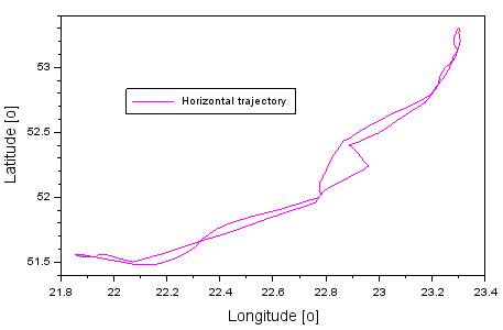
Fig. 1.
Horizontal trajectory of the aircraft

Fig. 2. Vertical trajectory of the aircraft
The second stage of the
experiment consisted of collecting the navigation data recorded by both
satellite receivers, followed by processing, transmitting and cataloguing these
data on a portable computer for further data processing. All GPS navigation
data were saved in one folder on the portable computer. For the navigation data
are included: the coordinates of the aircraft determined using the SPP code
method, the reference coordinates of the flight calculated using the RTK-OTF
differential technique, and the single accuracy results obtained for each of
the receivers Rx1 and Rx2. Apart from that, navigation data on the number of
GPS satellites tracked by receivers Rx1 and Rx2 were recorded.
The third stage of the
research consisted of the development and implementation of the mathematical
algorithm (1-4) in the given programming language. In this analysed case,
numerical calculations were performed in the Scilab v.6.0.0 language
environment [16]. Calculations were performed for a total of 9581 measurement
epochs, with 1s steps. Measurement weights were calculated from formula (4) for
both receivers Rx1 and Rx2. The results of the numerical calculations together
with their graphic representations and tables (Not presented) are presented in Section 5.
5. RESEARCH
RESULTS
The presentation of research
results begins with presenting the numbers of tracked GPS satellites for the
Rx1 and Rx2 receivers for the solution from the SPP code method. Figure 3 shows
the results of the (NSSPP,Rx1, NSSPP,Rx2) parameters.
Both Thales Mobile Mapper receivers recorded GPS signals from 5 to 8 satellites
during the flight test. For most of the flight, both satellite receivers
tracked at least 7 GPS satellites.
Next, Figure 4 presents the
measurement weights (α, β) calculated from equation (4). The values
of measurement weights for both Thales Mobile Mapper receivers range from 0.125
to 0.200. However, the value of the α weight coefficient is 0.141 and of
the β coefficient 0.137. The vales of the weight coefficients (α,
β) increase with the decreasing number of GPS satellites tracked by the
Rx1 and Rx2 satellite receivers. This is a reverse relationship, so when the
number of GPS satellites tracked by the Rx1 and Rx2 receivers increases, the
weight coefficients (α, β) decrease.
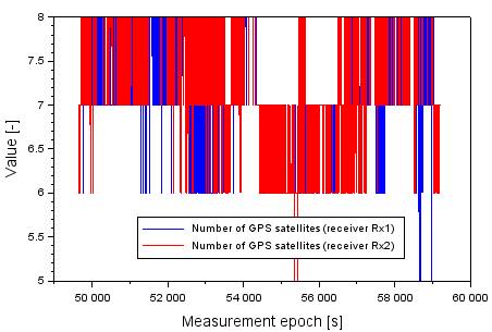
Fig. 3. Number of GPS satellites tracked during flight test
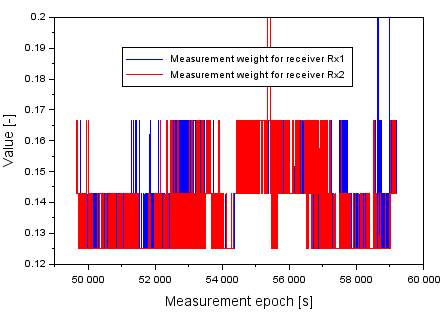
Fig.
4. Values of measurement weight (α,
β)
Figures 5 and 6 show the
results of single accuracy values for both Rx1 and Rx2 satellite receivers.
Hence, Figure 5 presents the results of position errors obtained for the Rx1
receiver. The values of the dBSPP,Rx1 parameter range from -7.71 to
+3.27 m, while values of the dLSPP,Rx1 parameter range from -5.30 to
+5.07 m. Finally, the results of the dhSPP,Rx1 parameter range from
-12.62 to +5.25 m. Figure 6 presents the results of position errors obtained
for the Rx2 receiver. The values of the dBSPP,Rx2 parameter range
from -9.61 to +0.67 m, while values of the dLSPP,Rx2 parameter range
from -6.91 to +5.73 m. Finally, the results of the dhSPP,Rx2
parameter range from -16.67 to +11.17 m. As one may notice in Figures 5 and 6,
the lowest positioning accuracy from the SPP solution is noted for the
ellipsoidal height component. On the other hand, the highest positioning
accuracy was noticed along the L axis.

Fig.
5. Values of position errors for receiver Rx1
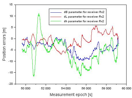
Fig. 6. Values of position errors for receiver Rx2
The results of single positioning accuracy presented
in Figures 5 and 6 are followed by Figure 7, which illustrates the final
results of the resultant accuracy value according to the algorithm (1-3). The
positioning accuracy for the B component ranged from -2.65 to +0.01 m. For the
L component, the accuracy ranged from -1.38 to +1.23 m, while for the vertical
component h, it falls into the range of -5.13 to +2.01 m.

Fig. 7. Values of resultant accuracy of aircraft position
6. DISCUSSION
The discussion focuses on
two research threads. First, the importance of the proposed mathematical
solution (1-4) for single accuracy values from single satellite receivers was
highlighted. The second research thread elaborates on the significance of the
contribution of this study to the current state of knowledge.
In the first part of the
discussion, the authors compared the obtained values of resultant accuracy with
single accuracy values for both GNSS receivers. To do this, the mean values of
aircraft positioning accuracy were compared. Figure 8 presents a comparison of
the (dB, dBSPP,Rx1, and dBSPP,Rx2) parameters in the form
of absolute values. The mean value of the dB parameter equals 0.9 m, while for
the dBSPP,Rx1 parameter, it is 2.4 m, and finally, for the dBSPP,Rx2
parameter, it equals 4.0 m. Based on these values, one may conclude that the
values of the dB parameter are decidedly lower than the results of dBSPP,Rx1
and dBSPP,Rx2. Therefore, the resultant accuracy dB is higher
than the results for parameters dBSPP,Rx1 and dBSPP,Rx2.
It may be stated that the resultant accuracy dB improved by over 62% in
comparison to the results of the dBSPP,Rx1 parameter, and by 78%
compared to the results of the dBSPP,Rx2 parameter.
Figure 9 presents a
comparison of the (dL, dLSPP,Rx1 and dLSPP,Rx2)
parameters in the form of absolute values. The mean value of the dL parameter
equals 0.1 m, of the dLSPP,Rx1 0.4 m, while for the dLSPP,Rx2,
it is 0.6 m. These values lead to the conclusion that the values of the dB
parameter are decidedly lower than the results of dLSPP,Rx1 and dLSPP,Rx2.
Thus, the resultant accuracy dL is higher than the results for parameters dLSPP,Rx1
and dLSPP,Rx2. One may conclude that the resultant accuracy dL
improved by over 85% in comparison to the results for the dLSPP,Rx1
parameter, and by 91% compared to the results of the dLSPP,Rx2 parameter.
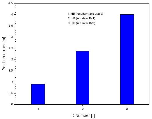
Fig.
8. Comparison of position errors along the B axis

Fig.
9. Comparison of position errors along the L axis
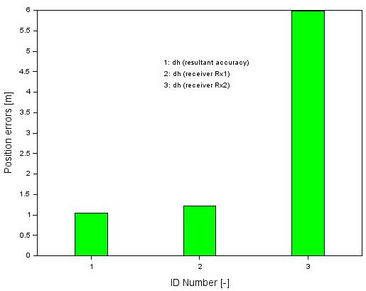
Fig.
10. Comparison of position errors along the h axis
Finally, Figure 10 presents
a comparison of the (dh, dhSPP,Rx1, and dhSPP,Rx2)
parameters in the form of absolute values. The mean value of the dh parameter
equals 1.0 m, for the dhSPP,Rx1, it is 1.2 m, while for the dhSPP,Rx2
parameter, it equals 6.0 m. These values lead to the conclusion that the values
of the dh parameter are decidedly lower than the results of dhSPP,Rx1
and dhSPP,Rx2. Hence, the resultant accuracy dh is higher than the
results for parameters dhSPP,Rx1 and dhSPP,Rx2. This leads
to the conclusion that the resultant accuracy dh improved by over 16% in
comparison to the results of the dhSPP,Rx1 parameter, and by 83%
compared to the results of the dhSPP,Rx2 parameter.
The second part of the discussion shows the
contribution of this study to the current state of knowledge. The obtained
positioning accuracy results are decidedly better than those presented in these
publications [13-15]. Similarly, the obtained research results are comparable
to or better than the results provided in some works [6-12]. It may be
concluded that the proposed navigation solution for mathematical equations
(1-4) improves the accuracy of aircraft positioning using the SPP code method
in the GPS satellite system. Thus, the algorithm (1-4) presented here may provide
an interesting solution for determining the accuracy parameter in aerial
navigation.
7. CONCLUSIONS
This article presents
the results of research on the determination of GPS positioning accuracy in
aerial navigation. Thus, a modified algorithm was created to determine the
accuracy parameter of a set of two GNSS satellite receivers installed onboard
an aircraft. The functioning of the algorithm was tested on actual GPS
measurement data using the SPP code positioning method. The analyses were
conducted on GPS satellite data from two Thales Mobile Mapper onboard receivers
installed in a Cessna 172 aircraft, which performed a test flight over the
airport in Dęblin. The performed calculations revealed that:
-
the resultant
positioning accuracy for the B component improved by 62-78% compared to the
single accuracy results for a single GNSS receiver;
-
the resultant positioning
accuracy for the L component improved by 85-91% compared to the single accuracy
results for a single GNSS receiver;
-
the resultant
positioning accuracy for the h component improved by 16-83% compared to the
single accuracy results for a single GNSS receiver.
The obtained test
results demonstrated that the algorithm applied to improve the GPS positioning
accuracy is correct and could be used in aviation and navigation operations.
References
1.
IGS MGEX Service. „Constellations”.
Available at: https://igs.org/mgex/constellations/.
2.
International Civil Aviation Organization. 2006. ICAO
Standards and Recommended Practices (SARPS), Annex 10, Volume I (Radio
Navigation Aids). Available at: http://www.ulc.gov.pl/pl/prawo/prawomi%C4%99dzynarodowe/206-konwencje.
3.
Felski A., K. Banaszek, T. Woźniak, P.
Zakrzewski. 2011. “Dokładność
serwisu EGNOS w kontekście obsługi operacji lotniskowych”. [In
Polish: “Acuuracy of EGNOS service
in airport operations”]. Zeszyty Naukowe Marynarki Wojennej 1(184)
LII: 31-44.
4.
Banaszek K., M. Malarski. 2011. “Dokładność pozycjonowania
współczesnych systemów nawigacji satelitarnej a
przepustowość portów lotniczych” [In Polish: “Position accuracy of modern satellite
navigation systems and airport capacity”]. Logistyka 4: 48-67.
5.
Grzegorzewski M., J. Ćwiklak, H.
Jafernik, A. Fellner. 2008. “GNSS for an Aviation”. TransNav,
the International Journal on Marine Navigation and Safety of Sea Transportation
2(4): 345-350.
6.
Beran T. 2008. Single-Frequency, Single-Receiver Terrestrial and
Spaceborne Point Positioning. Technical Report no. 257. Department
of Geodesy and Geomatics Engineering, University of New Brunswick: Fredericton,
NB, Canada.
7.
Murphy J.G., W.V. Cottrell. 1997. “Airborne
Testing of GPS+GLONASS Positioning Sensor Against A Proven Flight Test Truth
Source”. In: Proceedings of the
10th International Technical Meeting of the Satellite Division of The Institute
of Navigation (ION GPS 1997). Kansas City, MO, USA. 16-19 September 1997. P.
1047-1054.
8.
Lachapelle G., M.E. Cannon, W. Qiu,
C. Varner. 1995. “An Analysis of Differential and Absolute GPS Aircraft
Positioning”. In: Proceedings of
the 1995 National Technical Meeting of The Institute of Navigation.
Anaheim, CA, USA. 18-20 January 1995. P. 701-710.
9.
Lachapelle G., M.E. Cannon, W. Qiu,
C. Varner. 1996. “Precise aircraft single-point positioning using GPS
post-mission orbits and satellite clock corrections”. J. Geod. 70: 562-571.
10.
Chen K. 2005. Real-Time Precise
Point Positioning, Timing and Atmospheric Sensing. Ph.D. Thesis. University
of Calgary, Alberta, AB, Canada. UCGE Reports No. 20217.
11.
Chen K., Y. Gao. 2005. “Real-Time
Precise Point Positioning Using Single Frequency Data”. In: Proceedings of the 18th International
Technical Meeting of the Satellite Division of The Institute of Navigation (ION
GNSS 2005). Long Beach, CA, USA. 13-16 September 2005. P. 1514-1523.
12.
Le A.Q., C. Tiberius. 2007.
“Single-frequency precise point positioning with optimal
filtering”. GPS Solutions 11: 61-69.
13.
Grzegorzewski M. 2005.
“Navigating an aircraft by means of a position potential in three
dimensional space”. Annual Navigation 9:
1-11.
14.
Fellner A., H. Jafernik. 2014.
“Airborne Measurement
System During Validation of EGNOS/GNSS Essential Parameters in Landing”. Reports on Geodesy and
Geoinformatics 96: 27-37.
15.
Brzozowski M., M. Myszka, Z.
Lewandowski. 2008. “Pozycjonowanie statku
powietrznego w locie za pomocą odbiornika DGPS z funkcją odbioru
poprawek różnicowych z satelitów systemu EGNOS”. [In
Polish: “Positioning of flying aircraft by
the DGPS receiver with the option of differential corrections from EGNOS
satellite system”]. Problemy
Techniki Uzbrojenia 37: 41-48.
16.
Scilab website. Available at: https://www.scilab.org/.
Received 02.01.2022; accepted in
revised form 08.03.2022
![]()
Scientific Journal of Silesian University of Technology. Series
Transport is licensed under a Creative Commons Attribution 4.0
International License