Article citation information:
Stanik,
Z., Kubik, A., Hadryś,
D., Csiszár, C. Methods for
assessing the technical condition of bearing hubs in means of transport. Scientific Journal of Silesian University of
Technology. Series Transport. 2021, 113,
191-204. ISSN: 0209-3324. DOI: https://doi.org/10.20858/sjsutst.2021.113.15.
Zbigniew
STANIK[1], Andrzej KUBIK[2], Damian HADRYŚ[3], Csaba
CSISZÁR[4]
METHODS FOR ASSESSING THE TECHNICAL CONDITION OF BEARING HUBS IN MEANS
OF TRANSPORT
Summary. This article
presents two methods of testing bearing hubs, which may supplement the existing
subjective and unreliable methods of diagnostics of rolling bearings used in
wheel bearing hubs of motor vehicles and other means of road transport. One of
the most important elements responsible for the safety of a vehicle is the
bearing hub. Regular monitoring of the technical condition of bearings should
become an obligation at vehicle inspection stations when carrying out a
technical inspection of a vehicle, authorising it to travel on public roads.
This article presents the results of vehicle tests with signs of damage to
rolling bearings, using two test stands: one on which the dynamic balancer
acted as a device for accelerating the wheel, and the other, which was designed
as a test dedicated to automotive rolling bearings, where a dynamic weighbridge
was used as the wheel drive, made it impossible to test the wheel at lower
rotational speeds. The newly designed and manufactured bearing testing device
eliminates the disadvantages of the previous stand, and additionally, enables
the measurement of a fully loaded bearing hub, which enables the simulation of
real operating conditions on the bearing hub.
Keywords: vibration
diagnostics, bearing, wear, means of transport
1. INTRODUCTION
Increasing technological progress,
growing expectations of users and standards related to environmental protection
are one of the reasons for the growing use of rolling bearings in means of
transport. However, the degree of complexity of the construction of means of
transport is increasing, which in turn causes the extension of repair and
maintenance procedures, making access to bearing hubs more difficult compared
to the previous structures [1-3]. Often, rolling bearings, for example, in
automotive vehicles, despite a relatively low price, can cause damage to other
components and entire components due to failure, generating significant repair
costs. The significant function of transport means, including motor vehicles,
should also be considered in the entire logistics process aimed at moving
people and goods among other things. Thus, the reliability of the means of
transport has a great influence on the proper functioning of the transport.
Subsequently, breakdowns of motor vehicles caused by damage to rolling bearings
are often surprising, unexpected, disrupting the transport cycle. Therefore, it
is necessary to use reliable methods for assessing the technical condition of
rolling bearings used in road transport [4, 5].
The widespread use of rolling
bearings in the construction of machines and means of transport has many
advantages. The main advantages of rolling bearings are:
● low
movement resistance, which is especially important during start-up,
● standardising
the basic dimensions of the bearings, which facilitates their practical
application,
● compactness
of bearing hubs structure,
● motion
stability at low speeds,
● giving off a small
amount of heat,
● structural
materials of the shaft do not have a significant impact on the durability of
bearings and their functioning,
● the
amount of lubricant required is small, which usually makes bearing
maintenance-free.
Rolling bearings also have
disadvantages, including:
● the
need for high-quality steel susceptible to cracking and chipping,
● using specialised procedures related to bearing assembly,
● the
need to use specialised devices to prevent dirt,
● sensitivity
to lubricant contaminants, which results in repeated shortening of durability
[4-7].
One of the drawbacks that deserves
special attention is the generation of mechanical vibrations through bearing
hubs equipped with rolling bearings. This phenomenon is closely related to the
bearing geometry and the structural materials from which they are made.
However, the parameters of generated vibrations, after registration and
appropriate analysis, may become the basis for diagnosing the technical
condition of rolling bearings [8-12]. This method is used to diagnose other
elements in machines, including cars [13-18].
Automotive manufacturers do not
specify procedures or time periods for reviewing or replacing most rolling
bearings, including bearings fitted in car wheel bearing hubs. Vehicle control
stations and car services do not have a highly specialised
diagnostic procedure for diagnosing automotive rolling bearings. They refer
only to unreliable organoleptic methods consisting of auscultation of the
diagnosed placenta with or without a stethoscope. It is worth mentioning that
periodic rolling bearing diagnostics is regularly used in the industry,
especially concerning stationary rotor machines. However, it cannot be used
directly in motor vehicles, due to their completely different nature of
functioning associated with mobility, which often forces operation in transient
states.
This article presents original
methods for assessing the technical condition of rolling bearings using two
test stands.
2. DIAGNOSTICS OF ROLLING BEARINGS
The basic symptom related to the
functioning of rolling bearings is:
● generating noise
(both in the acoustic band and outside it),
● generating vibrations
in a wide frequency band,
● generating heat
● generating
electromagnetic field interference,
● the
appearance of wear products (for example, in a lubricant),
● degradation
of the internal structure of the material in the form of, for example,
corrosion, microcracks,
● the
state of cooperating surfaces of elements of tribological
pairs [19-21].
Rolling bearing diagnostics can be
carried out based on their observation and analysis. Considering the symptoms
described, they determine the diagnostic methods for disassembly and without
disassembly.
Treating the rolling bearing as a
mechanical vibration generator, the most common diagnostic method is vibration
diagnostics, based on the recording of time courses of parameters describing
the generated vibration. Obtained and properly processed time courses are used
to build measures of the technical condition of rolling bearings. The advantage
of this method is its assembly-free nature and a large amount of information in
a relatively short unit of time.
The course of rolling bearing damage
over time can be divided into three stages [21, 22]:
● noise
stage - the broadband nature of the acceleration of vibrations associated with
the normal operation of the bearing is narrowed to frequencies associated with
the operation of individual bearing components. However, the maximum
acceleration of housing vibrations takes on large values, which indicates the
need to replace the bearing with new ones.
● vibration
stage - the progressive degradation of the surface layer of rolling elements
results in a significant increase in the actual values of housing vibration
acceleration.
● thermal stage - there
is avalanche wear of the surface of the elements, which results in their
deformation and increasing friction is generated, causing a very high
temperature of the bearing hub, followed by failures.
Vibration diagnostics of rolling
bearings makes it possible to determine the suitability of a rolling bearing
for further operation at the noise stage.
This method clearly surpasses the
subjective and unreliable organoleptic methods currently used in the field of
vehicle service, which consists of detecting possible play or auscultation of
the bearing hub.
However, using this method entails
the need to consider many individual design features, including not only the
hub itself but also the entire vehicle, with particular emphasis on the
propulsion and running gear [23, 24]. Specialised
equipment is also required, for example, a device for accelerating non-driven
road wheels and an apparatus that records the signal from vibration
acceleration sensors.
The use of vibroacoustic methods allows for objective results, and the effectiveness of this
method depends on the correct selection of measuring points and ensuring the
right measurement conditions. The design of rolling bearings causes the
detection of damage to individual components of the bearings to cause another
disturbance in the vibroacoustic signal. In the frequency spectrum,
the local damage to each component corresponds to a different component, so
that spectral analysis can answer not only whether damage has occurred but also
which bearing element has been damaged [5, 21].
From an operational point of view,
however, it is more important to detect damage in the early stages of its
development or excessive wear than determining which bearing component has been
damaged. Observing the frequency spectrum for changes in the frequency
amplitudes of the characteristic bearings may enable this task. The repeat
frequencies of the damage-induced impressions are determined by formula 1 to 3
[5, 21].
Failure of the current element
causes a pattern to occur in the frequency component spectrum [5, 21]:
![]() (1)
(1)
where: D – bearing split diameter, d –
rolling element diameter, fr –
relative frequency of rotation between inner and outer raceways, β –
bearing operating angle.
The frequency caused by damage to
the inner raceway can be recorded with the formula [5, 21]:
![]() (2)
(2)
where: e – number of elements.
The frequency caused by damage to the outer raceway can be determined by the formula [5, 21]:
![]() (3)
(3)
Determining the amplitudes of characteristic frequencies and comparing them with the symptom database or with the results of measurements previously performed on the test subject allows one to determine whether there have been adverse changes in the technical condition.
3. METHODS OF DIAGNOSTIC OF ROLLING
The results of the conducted tests
indicate that it is possible to diagnose rolling bearings used in various means
of transport. The methods for
diagnosing rolling bearings using two test stands are presented in this
section. The tests were carried out on an Opel car model Corsa
D, in which various symptoms indicating damage to the wheel hub bearing could
be observed while driving. The research used vibroacoustic
measurements, which were then subjected to appropriate transformations and
analysis. For signal recording, a manual LMS SCADAS XS data acquisition module
was used. This enables the recording of 6 channels with a sampling frequency of
51.2 kHz and 3 vibration acceleration sensors. Signal transformations and
analysis were performed using the Matlab 2019b computing environment using the Signal Processing
Toolbox. For measuring the rotational speed of the wheel, a SELS
PCID-8ZP induction sensor with an operating range of
8 mm was used. Figure 1 shows the view of the mounted vibration acceleration
sensors in the test vehicle, together with the marking of the axis measurement
directions by the vibration acceleration sensors. Regardless of the test method
used, the vibration acceleration sensors remained mounted in the same places.
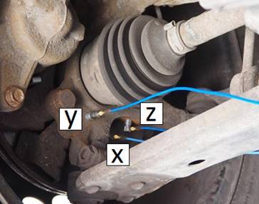
Fig. 1. View of placing vibration
acceleration sensors on the wheel hub of the tested vehicle
The methods for diagnosing rolling
bearings using two test stands are presented thus; The
first test post was the position described in Section 3.1. – dynamic balancer of the vehicle wheel. While the second test
bench was the position described in Section 3.2. – prototype
stand – stand designed for testing vehicle wheel bearing hubs.
3.1. Diagnostics of rolling bearings implemented with the use of the vehicle
wheel dynamic balancer
During the bench tests, the car was
raised on a two-column lift. A dynamic balancer was used to accelerate the
wheel, which enables acceleration of one wheel for two different values of
wheel speed. Figure 2 shows the performance of tests while accelerating the
wheel with a dynamic wheel balancer.
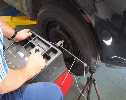
Fig. 2. Measurement stand during tests
During the tests, vibration
accelerations in three directions around the bearing hub were recorded. The
vibration signals and the rotational speed signal were recorded with a sampling
frequency of 51.2 kHz and stored in a digital form on the memory card of the
data acquisition device. Based on the mileage of the wheel speed signal, the
actual wheel speed was calculated. The wheel speed time course is shown in Figure
3. The time of execution of 4 full turns of the wheel was = 0.1027 s.
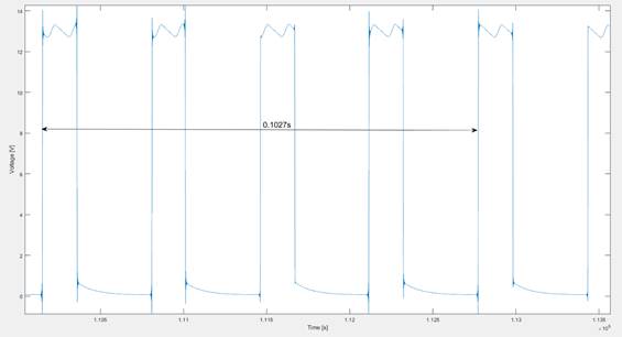
Fig. 3. Time course of the wheel speed signal - dynamic
balancer
A dynamic balancer accelerated the
wheel of the vehicle to a constant speed of 129.6 km/h, which corresponds to f_wheel = 37.5 Hz. Then, a spectral analysis of the
recorded signals was performed to search for frequencies characteristic of
damage to the individual elements of the bearing hub. Figure 4 presents an
analysis of the time-frequency waveforms of recorded signals.
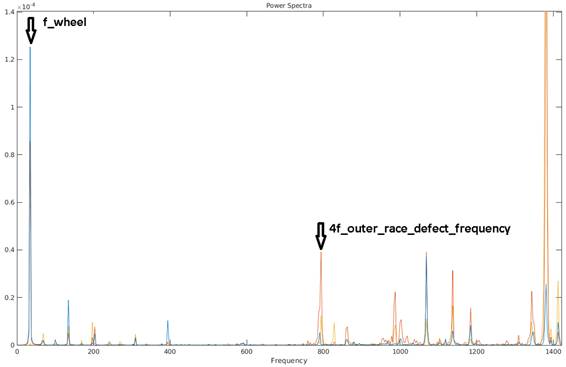
Fig. 4. Analysis of vibration signal waveforms of a
wheel with a damaged rolling bearing - dynamic balancer – where: blue
line - X-axis, red line - Y-axis, yellow - Z-axis
Based on the geometrical parameters of the bearing, the bearing failure frequency was determined for a bearing failure frequency of f_wheel = 37.5 Hz. Based on formulas 1 to 3, the following frequencies were calculated:
●
wheel speed frequency 37,50 Hz,
●
inner race defect frequency 307,54 Hz,
●
outer race defect frequency 217,46 Hz,
●
cage defect frequency 21,97 Hz.
As seen, the 4th harmonic of the
outer track damage frequency changes depending on the measurement axis. The
highest amplitude values are assumed for the Y-axis, which corresponds to the
vertical displacement of the bearing hub. Then the same measuring procedure was
used for the bearing hub with the new bearing. The same analysis of the
recorded vibration signal was also made. The
obtained results are a reference for earlier measurements and analysis of
vibration signals of a bearing hub equipped with a worn bearing. Comparison of
the obtained results enables the construction of measures of the technical
condition of the tested bearing hub. Figure 5 shows the time-frequency course
of vibration accelerations for a new bearing.
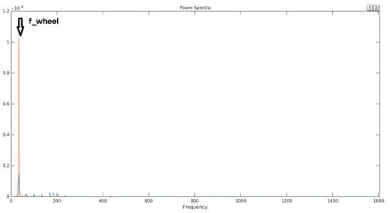
Fig. 5. Analysis of time-frequency waveforms of
vibration signals of a wheel with a new rolling bearing – where: blue
line - X-axis, red line - Y-axis, yellow - Z-axis
Figure 6 shows a comparison of
time-frequency courses of damaged vibration accelerations and a new rolling
bearing, whose measurements were made for the Y-axis. As seen in Figure 6, the
analysis of the time-frequency waveform of vibration signals shows the
differences between a signal with a damaged bearing (red line) and a signal
recorded with a new bearing (green). For a bearing junction with a new rolling
bearing, the time-frequency spectrum has no higher component frequencies, and
none of the frequencies characteristic of damage to individual bearing
components occurs.
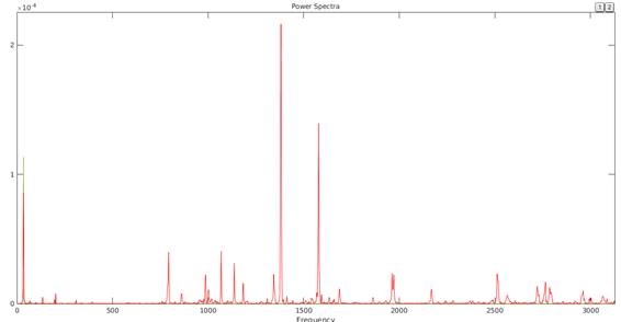
Fig. 6. Analysis of the time-frequency waveforms of the
road wheel - comparison of
a new and a damaged bearing - where green line indicates a new bearing,
red line indicates a damaged bearing
3.2.
Bearing diagnostics using a prototype stand dedicated to testing bearing hubs
Bench tests of the technical
condition of rolling bearings were carried out with the use of a typical
device, which is a dynamic wheel balancer. The dynamic wheel balancer has its
advantages, for example, ease of access and quick measurement. Due to the
limitations of the method presented in Section 3.1., a station for testing
rolling bearings of road wheels was designed and manufactured, which enables,
among others:
●
acceleration
and maintenance of constant speed of the road wheel in a wide range of
rotational speed,
●
measurement
of slip occurring between the wheel and the ground,
●
constant measurement of wheel pressure on the road.
During the tests, acceleration of
vibrations in the three axis directions and rotational speeds of the road wheel
and the drum driving the wheel near the bearing hub were recorded. The wheel
pressure on the device was mapped according to real conditions. The road wheel
was accelerated to a frequency of 5 Hz, which corresponds to a speed of 17.28
km/h. Reducing the wheel speed results in the
elimination of higher frequency components and simultaneously reduces the
signal amplitude. Figure 7 shows a partial view of the station and the tested
vehicle.
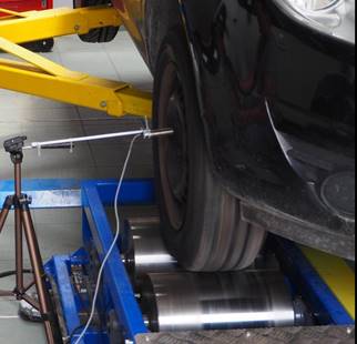
Fig. 7. Prototype stand during tests of the technical
condition of
the road wheel bearing hub
Based on the pulse time
course determining the speed of the driven road wheel, the vehicle speed is
determined. The results of
the analysis in the form of time
frequencies of wheel vibration signals with a damaged rolling bearing are shown in Figure
8.
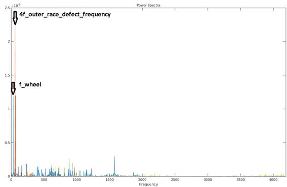
Fig. 8. Analysis of time-frequency waveforms of
vibration signals of a wheel with
a damaged rolling bearing - prototype stand – where: blue line - X-axis,
red line - Y-axis, yellow - Z-axis
A peak can be observed at a
frequency of 29 Hz. For the tested bearing hub, based on formulas 1 to 3, the
frequency of damage to individual rolling bearing components is:
●
shaft speed frequency 5,00 Hz,
●
inner race defect frequency 41,01 Hz,
●
outer race defect frequency 29,00 Hz,
●
cage defect frequency 2,93 Hz.
This frequency corresponds to the
frequency of damage to the outer race of the road wheel bearing.
Thereafter, the damaged bearing hub
was replaced with a new one. The whole wheel bearing was tested again. The
result of the time-frequency analysis of the new bearing hub is shown in Figure
9.
Then, the results of the
time-frequency analysis of damaged and new bearings were compared, and the results are shown
in Figure 10.
As observed, the value for a damaged
bearing frequency = 29 Hz is 2.7x10^-5 m/s2
and is almost three times higher than for a new bearing. In
addition, there are higher frequency components for the damaged bearing that
are not present for the new bearing.
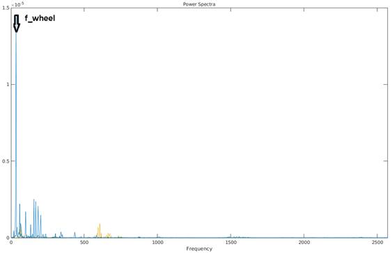
Fig. 9. Analysis of time-frequency waveforms of
vibration signals of a wheel with
a new rolling bearing-where: blue line - X-axis, red line - Y-axis, yellow -
Z-axis
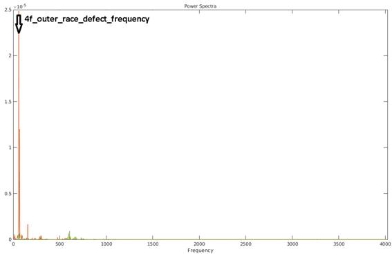
Fig. 10. Analysis of the vibration time-frequency
waveforms - comparison of signals with new and damaged bearing - where green
line indicates a new bearing, red line indicates
a damaged bearing
4. SUMMARY
The testing methods of bearing hubs
presented in this paper may complement existing, subjective and unreliable
methods of rolling bearing diagnostics used in the bearing hubs of road wheels
of motor vehicles and other means of road transport. Bearing hubs are one of
the most important elements responsible for the safety of a motor vehicle.
Regular monitoring of the technical condition of bearings should become an
obligation at vehicle inspection stations when performing the technical
inspection of a vehicle entitling the vehicle to drive on public roads.
The methods for diagnosing rolling
bearings were presented using two test stands. The first test post was the
position described in Section 3.1. – dynamic
balancer of the vehicle wheel. The second test bench was the position described
in Section 3.2. – prototype stand – stand
designed for testing vehicle wheel bearing hubs.
The vehicle with symptoms of rolling
bearing damage was tested using two test stands. One, in which a dynamic
balancer was used as a wheel acceleration device, and the other, which was
designed as a dedicated test for automotive rolling bearings. The previous
stand, where a dynamic weighbridge was used as the wheel drive, made it
impossible to test the wheel at lower rotational speeds. It was impossible to
map real conditions, for example, those prevailing in urban conditions. In
addition, an error resulting from the acceleration of the road wheel itself was
introduced, because the accelerated wheel was a side part of the tyre. This type of acceleration introduces an additional
normal force in the direction of the rolling bearing. Thus, this type of error
may cause the generation of additional vibrations or damping of damage, which
will be the subject of further research.
The designed and constructed device
for testing bearings eliminates the previous disadvantages of the previous
stand. In addition, it enables measurement of a fully loaded bearing hub. This
allows simulation of the real conditions operating on the bearing hub.
Test results presented in this
paper, regardless of the method used, showed that the outer race of the rolling
bearing was damaged. Picture 11 shows the damage to the outer race of the
rolling bearing, which was detected with the help of the aforementioned testing
devices.
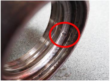
Fig. 11. View of
damage to the outer race of the rolling bearing of the tested vehicle
Comparing the results of both
methods, it can be concluded that the time-frequency waveforms of vibration
signals differ from the method used. Using the balancing method, additional
components are generated in the higher frequency range. These vibration signals
are levelled during tests in which a stand dedicated to tests of rolling
bearings of road wheels of means of transport was used.
References
1.
Randall Robert.
2011. Vibration-based Condition Monitoring: Industrial, Aerospace and
Automotive Applications. Chichester: Wiley. ISBN:
978-0-470-74785-8.
2.
Chiliński Bartosz. 2014. “The proposal of the bearing
arrangement to work in a swinging motion”. Mechanical Overview 1
(14): 15-18. ISSN 2354-0192.
3.
Figlus Tomasz. 2019. “A Method
for Diagnosing Gearboxes of Means of Transport Using Multi-Stage Filtering and
Entropy”. Entropy 21(5): 1-13. ISSN 1099-4300.
4.
Batko Wojciech,
Mikulaski Andrzej. 2002. „The use of wavelet
methods in the vibroacoustic monitoring systems of
the hoisting device bearing”. Diagnostyka 26: 7-12. ISSN
2449-5220.
5.
Cioch
Witold, Oskar Knapik, Jacek Leśkow. 2013. “Finding a frequency signature for a cyclostationary signal with applications to wheel bearing
diagnostics”. Mechanical Systems and Signal Processing 38(1):
55–64. ISSN 0888- 3270.
6.
Dąbrowski Zbigniew, Jacek Dziurdź.
2007. “New concept of using coherence function in digital signal
analysis”. Machine Dynamics Problems 31(3): 25-31. ISSN 0239-7730.
7.
Deuszkiewicz Piotr, Stanislaw Radkowski. 2003. “On-line condition monitoring of
a power transmission unit of a rail vehicle”. Mechanical System
and Signal Processing 17(6): 1321-1334. ISSN 0888- 3270.
8.
Engel Zbigniew. 1981. Vibrations in technology. Wrocław: The Ossoliński
National Institute. ISBN
83-04-00646-4.
9.
Junsheng Cheng, Yu Dejie, Yang Yu. 2007. “Application of an impulse
response wavelet to fault diagnosis of rolling bearings”. Mechanical
Systems and Signal Processing 27(2): 920-929. ISSN 0239-7730.
10. Zhou
Tong, Yuan Li, Yijia Jing , Yifei Tong. 2021. “Bearing Fault Identification Based on Deep Convolution
Residual Network”. Mechanika 27(3): 229-236. ISSN: 1392-1207.
11. Wang Jingyue, Haotian Wang, Lixin Guo,
Diange Yang. 2018. “Rolling bearing
fault detection using autocorrelation based morpho-logical filtering and empirical mode decomposition”. Mechanika 24(6): 817-823. ISSN:
1392-1207.
12. Bensana
T., S. Mekhilef. 2016. “Numerical
and experimental analysis
of vibratory signals for
rolling bearing fault diagnosis”. Mechanika
22(3): 217-224. ISSN: 1392-1207.
13. Czech Piotr. 2011. „Diagnosing
of disturbances in the ignition
system by vibroacoustic signals
and radial basis function - preliminary research”. Communications
in Computer and Information Science 239: 110-117.
DOI: https://doi.org/10.1007/978-3-642-24660-9_13.
Springer, Berlin, Heidelberg. ISBN: 978-3-642-24659-3. ISSN: 1865-0929. In: Mikulski Jerzy (eds), Modern transport telematics,
11th International Conference on Transport Systems Telematics, Katowice Ustron,
Poland, October 19-22, 2011.
14. Czech Piotr. 2013. „Intelligent
Approach to Valve Clearance Diagnostic in Cars”. Communications
in Computer and Information Science 395: 384-391.
DOI: https://doi.org/10.1007/978-3-642-41647-7_47.
Springer, Berlin, Heidelberg. ISBN: 978-3-642-41646-0; 978-3-642-41647-7. ISSN:
1865-0929. In: Mikulski Jerzy (eds), Activities of transport telematics,
13th International Conference on Transport Systems Telematics, Katowice Ustron, Poland,
October 23-26, 2013.
15. Czech Piotr. 2013. „Diagnosing
a car engine fuel injectors' damage”. Communications in Computer
and Information Science 395: 243-250. DOI: https://doi.org/10.1007/978-3-642-41647-7_30. Springer, Berlin,
Heidelberg. ISBN: 978-3-642-41646-0; 978-3-642-41647-7. ISSN: 1865-0929. In:
Mikulski Jerzy (eds), Activities of transport telematics, 13th International Conference on Transport Systems Telematics, Katowice Ustron,
Poland, October 23-26, 2013.
16. Graževičiūtė J., I. Skiedraitė, V. Jūrėnas,
A. Bubulis, V. Ostaševičius.
2008. „Applications of high frequency vibrations for surface milling”. Mechanika
1: 46-49.
17. Ubartas M., V. Ostaševičius, S. Samper,
V. Jūrėnas, R. Daukševičius.
2011. „Experimental investigation
of vibrational drilling”.
Mechanika 4: 368-373.
18. Ostaševičius V., V. Jurėnas, M. Žukauskas.
2014. „Investigation of energy
harvesting from high frequency
cutting tool vibrations”. Mechanika
5: 500-505.
19. Raymond A. Guyer. 1996. Rolling
Bearings Handbook and Troubleshooting Guide, Ohio: Taylor & Francis.
ISBN 97-80-801988-714.
20. Radkowski Stanislaw. 2008. “Vibro-acoustic
diagnostics of low-energy stage of failures evolution”, Proceedings of
the Institution of Mechanical Engineers Part G Journal of Aerospace Engineering
223: 589-597. ISSN 0954-4100.
21. Stanik Zbigniew. 2013. Diagnosing rolling bearings of motor
vehicles with vibroacoustic methods. Radom:
Scientific Publisher of the Institute of Sustainable Technologies - National
Research Institute. ISBN 978-83-7789-204-6.
22. Cempel Czesław. 1978. Applied vibroacoustics.
Warszawa: PWN. ISBN 83-01-09034-0.
23. Maláková Silvia, Matej Urbanský,
Gabriel Fedorko, Vieroslav Molnár, Samuel Sivak.
2021. „Design of geometrical parameters and kinematical characteristics of a non-circular
gear transmission for given parameters”. Applied Sciences
11(3): 1-23. ISSN: 2076-3417.
24. Maláková Silvia, Michal Puškár, Peter Frankovský, Samuel Sivák,
Maroš Palko, Miroslav Palko. 2020. „Meshing Stiffness - A Parameter Affecting the Emission of Gearboxes”. Applied Sciences
10(3): 1-12. ISSN:
2076-3417.
Received 08.09.2021; accepted in
revised form 13.11.2021
![]()
Scientific Journal of Silesian University of Technology. Series
Transport is licensed under a Creative Commons Attribution 4.0
International License