Article citation information:
Shpachuk, V.,
Chuprynin, A., Suprun, T., Kovalenko, A. Mechanical
interaction of the rail transport car and joint irregularity. Scientific Journal of Silesian University of
Technology. Series Transport. 2021, 113,
173-189. ISSN: 0209-3324. DOI: https://doi.org/10.20858/sjsutst.2021.113.14.
Vladimir SHPACHUK[1], Aleksandr CHUPRYNIN[2], Tatiana
SUPRUN[3], Andriy KOVALENKO[4]
MECHANICAL INTERACTION OF THE RAIL TRANSPORT CAR AND JOINT IRREGULARITY
Summary. Mechanical
models of a transport system “carriage - track” while crossing a
joint irregularity are proposed. An investigation was conducted on the
peculiarities of static, shock and dynamic interaction between the four-axle
car and the track, considering tram wheelsets motion features over joint
irregularity. A method to solve the equations of a mathematical model of
static, shock and dynamic interaction is developed. Numerical analysis is used
to determine deflections of the facing rail under the first sleeper for each
phase of motion depending on motion phases, and car load and speed.
Keywords: railway
rolling stock, four-axle car, track, ballast, joint irregularity, trailing
rail, facing rail
1. INTRODUCTION
In the current state
of rail transport operating conditions, one should pay special attention to
improving its design, as well as improving the reliability and operational
properties of rolling stock. This is why in electric transport,
scientific and technical works and research related to solving problems,
devoted to the problem of ensuring the reliability of the tramcar-rail
complex are particularly important at the present stage of development. Thus,
scientific and technical papers and investigations that provide task solutions
devoted to the problem of ensuring the reliability of the tramcar-track
complex are particularly important in the electric transport area at the
current stage of development.
When a tramcar moves,
its components and assemblies are affected by the interaction forces that arise
between the cars and the trolleys, the trolleys wheel pairs and the upper
structure of the track. They change both in time and in direction. Problem
solutions related to the investigation of the practical application of the
mechanical interaction science of rolling stock and rail tracks significantly
affects the development of electric transport and the safety of railcars, as
well as on the capacity of stations, on the economy of maintenance of rolling
stock and rail tracks, conditions of overall cross-country ability of rolling
stock, etc. At the same time, the deformation characteristics of the ballast
layer under the rail supports (parameters of elastic and residual sediment)
ultimately regulate the technical resource and duration of its operation.
Practice shows that the greatest sediment of the ballast layer occurs in places
of butt irregularities under the first sleepers of the facing rail. This is
because these places of the rails are usually subjected to the greatest dynamic
load of the impact type.
Subsequently, investigations of the mechanical interaction processes in
the system «tramcar - track»
are becoming important, as well as establishing new regularities based on the
analysis results, noting the peculiarities of their static, impact and dynamic
interaction while considering the operating, design and mechanical parameters
of the tramcar and upper truck structure and motion phase of the tramcar
through joint irregularity.
2. LITERATURE
REVIEW AND RESEARCH OBJECTIVE
Currently, significant attention is given
to the development of the transport structure in many countries of the world.
In addition, funds are been invested into the track and railway rolling stock.
The world`s experience indicates mechanical complex`s «tramcar -
track» reliability and durability indicators to depend on
the characteristics of the joint operation of rolling stock and track, the type
of rolling stock, the type of rails and sleepers, and the operating conditions
of the mechanical system. It also depends on the ability to resist the
destructive effects of the resulting shock and vibration loads.
Furthermore,
it is known that the highest level of deposition of the ballast layer occurs
under the first sleeper of the facing rail. This is because the first sleeper
under the facing rail in these places usually experiences the greatest force
interaction between the tramcar and the upper structure of the track due to
their impact. Thus, the deflection of the facing rail under the first sleeper
is a significant indicator that corresponds to the features of mechanical
interaction of the receiving rail of the track when investigating static,
impact and dynamic interaction with the upper structure of the track in places
with isolated butt joints of the track.
Investigation analysis dedicated to the
mechanical interaction of a four-axle car and a rail track shows [1] that the
weakest link in the system is the isolated zones of the track joints. Further,
it is similarly known that the highest level of deposition of the ballast layer
occurs under the first sleeper of the receiving rail. This is because in these
places the first sleeper under the receiving rail usually experiences the
greatest force interaction between the tramcar and the upper structure of the
track due to their impact. Thus, the deflection of the receiving rail under the
first sleeper is a significant indicator that corresponds to the features of
the mechanical interaction of the receiving rail of the track in the investigation, static, impact and dynamic interaction
with the upper structure of the track in places with isolated butt joints of the
track.
In addition, the expediency of
considering the phases of movement through joint irregularity [2], as well as the stiffness characteristics
of the ballast layer of the track is emphasised. The issues of joint operation
of rolling stock and rail track are also analysed, determining the features of
their static [1, 3] and dynamic interaction [4] during the passage of joints by
the car.
Various factors that change
during the operation of the rail track make it necessary to apply an integral
model that considers various impact factors.
Thus, this research, devoted to the improvement of existing models of
interaction between the car and the upper structure of the track, is modern and
relevant.
The load of rolling stock
elements and the upper structure of the track determining the parameters of
durability in operation [5], the strength and rigidity of the track [6], are
conducted in the field. This together, affects the technical resource and
service life. Operational experience of rail transport shows that the
"car-track" indicators of reliability and durability in the
mechanical complex significantly depend on the features of the interaction
processes between the track and rolling stock and the operating conditions of
the system under consideration. In addition, this interaction affects the
ability of the system to withstand the destructive effects of the resulting
shock and vibration loads [7], which are cyclically repeated.
To analyse the mechanical
interaction of rolling stock and the upper structure of the track, it is
necessary to solve several related problems. Much attention is focused on these
issues and a sufficient amount of new research is emerging in this area.
2.1. Analysis of recent studies
Most scientific works are currently limited to the
consideration of individual parameters of the electric transport operation. To
ensure a reliable modelling, it is necessary to use the most generalised
approach from possible ones, which considers the totality and mutual influence
of various factors [8].
Improving the quality
and capacity of existing services and developing new infrastructure are essential
to meet the growing demand for high quality and reliable logistics of goods and
people. The efficiency and reliability of the path design are crucial for a
successful operation. Many modern rail track investigations focus on specific
aspects of design and operation, such as fatigue [7], ballast destruction [6],
ride comfort [1], noise or vibration [2].
Thus, some works [5], present the processes of mechanical
interaction in the "car-track" system, where they are considered only
taking into account the movement of the vehicle on non-jointed sections of the
track. Other works [7] do not observe the boundary conditions for the facing
rail. In practice, this does not correspond to the conditions of real
mechanical loading of a tramcar, sections of the trailing and facing rails.
Therefore, the values of the structural speed of rolling stock determined in
the studies are not sufficiently complete and needs to be improved.
Thus, there is a need to develop a sufficient and
easy-to-use model of the mechanical interaction of rolling stock and track.
Additionally, an analysis technique considers a rail car as a multidimensional
discrete one, and the upper structure of the track as a continuous system. In this
formulation, the characteristics of mechanical interaction in the
"car-track" system in the joint area will correspond to the actual
loading conditions.
2.2. Purpose and research objective
This
study investigates the mechanical interaction of the car and the upper
structure of the track for the improvement of the parameters of a
discrete-continuous system by rationally selecting and optimising the
parameters of its components. This will provide an additional impact on the
reliability and durability of the system through components that depend on the
parameters of dynamic interaction in the transport mechanical complex
"car-rail track on a section with isolated joint
irregularity".
Hereby, one can formulate
the following research task:
·
to create a method of sequential static-impact-dynamic calculation
of deflections of the facing rail under the first sleeper in the growth phase,
considering the phases of movement of the tramcar relative to the butt joint;
·
to study the influence of the phases of movement of the tramcar on
the height of the joint when varying the operational, structural and mechanical
parameters of the tramcar and the upper structure of the track;
·
to improve the dynamic model of deflections of the receiving rail
under the first sleeper in the growth phase, noting the characteristics of the
elastic suspension of the tramcar, the ballast layer, as well as the
quantitative parameters of the reduced masses of the wheels corresponding to
the phase of movement of the tramcar;
·
analyse the features of the influence of operational, structural
and mechanical parameters of the tramcar and the upper structure of the track
on the deflections of the receiving rail under the first sleeper in the growth
phase.
3. RESEARCH MODEL AND METHOD
A mechanical discrete-continuous model of a four-axle car
is considered. This can be a tramcar, a passenger or a freight car of a
railway transport. This takes into account the multi-factor influence of
structural, operational and mechanical parameters of the "car-rail track
on a section with isolated butt joint" system. These are car speed,
its loading, the conditions for connecting the facing and trailing rails to
each other through the butt rail cover, the rigidity of the ballast layer, and
others.
The phases of the car movement during static interaction
are determined as follows: in the first phase, all wheelsets are located on the
trailing rail, in the second phase – three remain on it, in the third
– two and in the fourth only one. At the same time, accordingly, the
number of wheels on the facing and trailing rails affect their static
deflections, that is, the height of the joint
irregularity that is created.
The calculated mechanical scheme
of the dynamic interaction processes of the facing rail with the vehicle in the
joint area on the example of the third phase of the car's movement is shown in
Figure 1. This scheme differs from the processes of static interaction, as well
as other phases of movement of the facing rail in conditions of dynamic interaction.
Currently, there is only one wheel on the trailing rail, and all three on the
facing rail.
Here c1,
b1 – suspension
stiffness and damping coefficient; c2, b2 – ballast stiffness and damping
coefficient; ![]() – stiffness
of the rail at its end; m1, m1
– reduced masses of the wheel and the car, considering the load; y1, y1 – displacement
of reduced mass of the wheel and the car;
– stiffness
of the rail at its end; m1, m1
– reduced masses of the wheel and the car, considering the load; y1, y1 – displacement
of reduced mass of the wheel and the car; ![]() ,
, ![]() – geometrical
coordinates of the elastic supports, as well as the
wheels of the first and second axles of the car.
– geometrical
coordinates of the elastic supports, as well as the
wheels of the first and second axles of the car.
Accordingly, the number of wheels on the facing rail
significantly changes its mechanical load relative to the oscillatory motion,
both relative to the car and the ballast layer.
When calculating deflections of a discrete-continuous
system, mechanical, geometric characteristics, static deflections, and
post-impact velocity are set for the receiving rail. Deflections of the system
are considered as a superposition of the first five eigenvalues of vibrations
of the receiving rail as a discrete-continuous mechanical system.
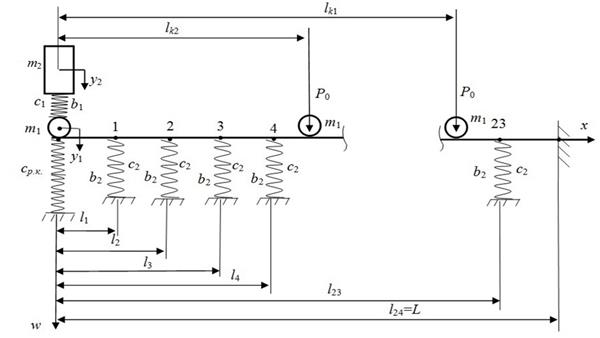
Fig. 1. Calculated mechanical scheme of dynamic interaction for
the facing rail during the first phase of the car motion
3.1. Static interaction
The essence of the static interaction of the car and the
rail track assumes the height determining of the joint irregularity by the
initial parameters method based on elastic lines of the facing and trailing
rails, which loading corresponds to all four phases of the car's movement.
In the static calculation of rail deflections, a model of a multi-span
beam is used on 24 elastic supports (23 sleepers and a support that simulates
the connection to an adjacent rail through a working pad) and is shown in the
third phase of the car's movement in Figure 2. The force factors here that
ultimately determine the static deflection of the facing and trailing rails, as
well as the height of the joint corresponding to the third phase of movement of
the tramcar, are constant forces Р0. They
correspond to the current number of wheel pairs on the rails and have
coordinates: for the facing rail (Figure 2a)
ХВj, where ![]() – tramcar wheelset number; for the facing rail (Figure 2b) ХПj
(j=1, 2).
– tramcar wheelset number; for the facing rail (Figure 2b) ХПj
(j=1, 2).
In Figure 2: ![]() ,
, ![]() – geometric coordinates
of elastic supports;
– geometric coordinates
of elastic supports; ![]() – load
on the side of a tramcar per wheel; Р0 – weight of a tramcar, including
its load;
– load
on the side of a tramcar per wheel; Р0 – weight of a tramcar, including
its load; ![]() –
elastic force applied in the third phase of movement of the tramcar to the end
of the facing rail from the side of the trailing rail when
–
elastic force applied in the third phase of movement of the tramcar to the end
of the facing rail from the side of the trailing rail when ![]() m;
m; ![]() –
deflection of the facing rail at the end in the third phase of the tramcar
movement; Q0, M0
– cross force and bending moment at the origin of the coordinates;
c – stiffness of the ballast
layer under the sleeper of the upper track structure;
–
deflection of the facing rail at the end in the third phase of the tramcar
movement; Q0, M0
– cross force and bending moment at the origin of the coordinates;
c – stiffness of the ballast
layer under the sleeper of the upper track structure; ![]() m;
m; ![]() m;
m; ![]() m;
m; ![]() m;
m; ![]() m;
m; ![]() m;
m; ![]() m;
m; ![]() m;
m; ![]() m;
m; ![]() m;
m; ![]() m;
m; ![]() m;
m; ![]() m;
m; ![]() m;
m; ![]() m;
m; ![]() m;
m; ![]() m;
m; ![]() m;
m; ![]() m;
m; ![]() m;
m; ![]() m;
m; ![]() m;
m; ![]() m;
m; ![]() m;
m; ![]() m;
m; ![]() m;
m; ![]() m;
m; ![]() m.
m.
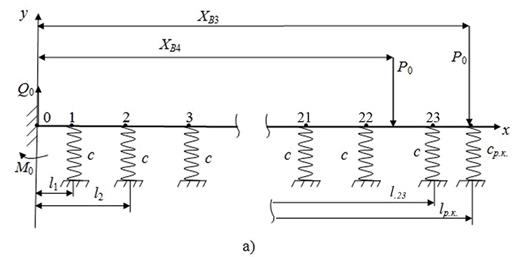
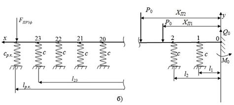
Fig. 2. Calculated mechanical schematic
of static interaction
during the third phase of the car motion:
a) trailing and b) facing rails
The equation of the curved axis of the rails in the first phase of
movement is written using the method of initial parameters, noting the
conditions of their fixation ![]() :
:
trailing rail:
 ,
(1)
,
(1)
facing rail:
 . (2)
. (2)
The
elastic lines of the facing and trailing rails
in the third phase of movement are shown in Figure 3,
where уВ3, уВ4, уП1, уП2, у23 – deflections of the rails,
respectively, under the wheels of the car and the first sleeper of the
receiving rail.
The current height of the joint irregularity in the third phase of the
tramcar movement is calculated by the expression:
![]() ,
(3)
,
(3)
Where:
![]() –
deflections of the facing and trailing rails
at the ends, respectively, when
–
deflections of the facing and trailing rails
at the ends, respectively, when ![]() m, that is
m, that is ![]() ,
, ![]() .
.
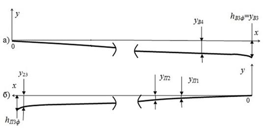
Fig. 3. Elastic lines of the trailing a)
and facing b) rails in the third phase of
the tramcar movement
Considering the fact that expressions (1) and (2) contain summands on
the right side, which in turn depends on deflections, the solution of these
equations is performed numerically according to the work algorithm. The
calculations were performed following the mechanical scheme of the tramcar and
the rail track, as shown in Figure 1, as well as geometric and
mechanical characteristics of the Р-65 rail and T-3 tram [9]: elastic modulus of the rail material – ![]() N/m2; moment of inertia of the rail section
relative to the neutral axis –
N/m2; moment of inertia of the rail section
relative to the neutral axis – ![]() cm4; path ballast layer stiffness –
cm4; path ballast layer stiffness – ![]() N/m. Mass of a tramcar reduced to one wheel (empty)
N/m. Mass of a tramcar reduced to one wheel (empty) ![]() kg, when maximum (with 193 passengers) uploaded –
kg, when maximum (with 193 passengers) uploaded –
![]() kg.
kg.
The
established values of the joint stage value in the third phase of the tramcar
movement (![]() mm) makes it possible (using mass, load and reduced wheel
mass) to determine the value after the impact speed of the facing rail at the
end at the stage of impact interaction.
mm) makes it possible (using mass, load and reduced wheel
mass) to determine the value after the impact speed of the facing rail at the
end at the stage of impact interaction.
3.2. Impact in reaction
This work mainly discusses the peculiarities, assumptions, and expressions for
determining the post-impact vertical velocity of the end face of the facing
rail. The results obtained are used further at the stage of dynamic interaction
in the form of initial data when calculating deflections of the facing track
rail under the first sleeper during its growth phase. It is established that in
the third phase of movement of the tramcar, the post-impact speed changes in
the range of ![]() m/s. The results obtained are used as
initial data when calculating the deflections of the facing track rail under
the first sleeper during its growth phase.
m/s. The results obtained are used as
initial data when calculating the deflections of the facing track rail under
the first sleeper during its growth phase.
3.3. Dynamic interaction
The solution of the formulated problem is carried out by the method of sequential static-impact-dynamic calculation. It is based on the principle of superposition of the action of forces with respect to elastic linear systems that deform [10].
Structurally, the method consists of the following three steps.
Stage 1. Here we consider the problem of free vibrations of the mechanical system “tramcar- rail track”, which is reduced to a superposition of eigenforms. This does not consider the components associated with the phenomena of dissipation, as well as the impact of static load from the tramcar on the facing rail. In a generalised form for all phases of movement of the tramcar, the deflections of the receiving rail considering the geometric coordinates and sprung mass of the tramcar are determined by the expressions:
![]() ,
,
![]() (4)
(4)
![]() ,
,
where Ds, Ms – constant integrations, coefficients found from the conditions of orthogonality of oscillation forms, considering the pre-impact speed of the wheel of the third wheelset (defined in Section 3.2 of this paper) and the post-impact speed of the rail compatible with the wheel; ![]() ,
, ![]() – eigenvalues
and eigen frequencies of
vibrations of the facing rail as a system with distributed parameters; l*
– linear mass
coordinate m1.
– eigenvalues
and eigen frequencies of
vibrations of the facing rail as a system with distributed parameters; l*
– linear mass
coordinate m1.
Stage 2. Here, an exponential component is
superimposed on the solution of expression (4):
![]() ,
(5)
,
(5)
where hs – damping coefficient of the corresponding waveform.
In
addition, the dissipation factor is determined by the expression ![]() , where bs – coefficient of resistance
relative to the corresponding waveform;
, where bs – coefficient of resistance
relative to the corresponding waveform; ![]() – reduced
weight of the rail. In calculations, it is
– reduced
weight of the rail. In calculations, it is ![]() kg,
kg, ![]() N·s/m
(independent from s [10]).
N·s/m
(independent from s [10]).
Step
3. On the elastic line ![]() of the facing rail, defined for
the third phase of movement in Section 3.1, according to the superposition
principle, the deflection of the facing rail is superimposed by the addition method, which is
calculated in step 2 by formula (5), also see the diagram in Figure 4, where:
of the facing rail, defined for
the third phase of movement in Section 3.1, according to the superposition
principle, the deflection of the facing rail is superimposed by the addition method, which is
calculated in step 2 by formula (5), also see the diagram in Figure 4, where:
![]()
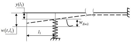
Fig. 4. Deflection diagram of the facing rail under the first sleeper
This method provides determination
of the deflection under the first sleeper of the facing rail in dynamics,
depending on the phase of movement of the tramcar due to joint irregularity,
structural and mechanical characteristics of the tramcar and the rail track. A flowchart of the method for determining the parameters of the mechanical
interaction of the tramcar and the rail track in the area of the track
junction, providing determination of deflections of the facing rail track under
its first sleeper in the growth phase from the loading parameters and speed of
the tramcar is shown in Figure 5,
where 1, 2, and 3 are blocks for calculating static, impact, and dynamic
parameters of the mechanical interaction of the tramcar with the rail track,
respectively; ![]() – vector of joint height parameters
corresponding to the car's movement phases (section 3.1);
– vector of joint height parameters
corresponding to the car's movement phases (section 3.1); ![]() – vector of
rail stiffness at the end and static deflections of the facing rail under the
first sleeper (Section 3.1);
– vector of
rail stiffness at the end and static deflections of the facing rail under the
first sleeper (Section 3.1); ![]() –
post-impact velocity vector of the facing rail (Section 3.2);
–
post-impact velocity vector of the facing rail (Section 3.2); ![]() – vector of parameters of
maximum deflections of the facing rail under the first sleeper (Section 3.3).
– vector of parameters of
maximum deflections of the facing rail under the first sleeper (Section 3.3).
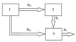
Fig. 5. Flowchart of the method
To calculate the deflections of the facing rail under the first sleeper in the zone of butt unevenness, the dynamic interaction of the tramcar with the rail track in the joint irregularity is considered with the following factors. The height of the joint irregularity corresponds to [3] the parameters of static interaction of the car, its loading, structural and operational factors of the mechanical system "tramcar – rail track". Dynamic characteristics after impact interaction at the growth phase of deflections of the facing rail under the first support are determined noting the parameters of a real object in the form of a tramcar and a rail track in a zone of isolated joint irregularity of the "gap – step up" type.
To achieve the goal, the following tasks were solved:
·
using
modelling methods, the mechanical system was represented in the form of a
multi-span beam on elastic supports;
·
the
butt plate is an equivalent elastic element at the end of the facing and trailing rails of the joint with a
stiffness coefficient that is determined considering its flat stress state.
With
the impact interaction of the wheel with the end face of the facing rail, a
tramcar interacting with the facing rail is considered as a sprung reduced
mass. In addition, the current step height is determined taking into account
the static interaction of the tram with the rail track, which corresponds to
the phase of movement of the tramcar due to the joint irregularity.
When analyzing the processes of dynamic interaction in the
system «two-dimensional discrete elastic – dissipative system –
continuous system in the form of an indistinguishable multi-span beam on 24
elastic supports», the following assumptions were made. When the wheel hits
the end face of the facing rail, it does not break off, as well as its sliding
relative to the rail; vibrations of the wheelset and the rail head occur in
continuous mode (since m2>>m1, the assumption is acceptable); deflections of the rail
are realised without violating the integrity of the ballast layer (since the deformation
characteristics of the ballast layer under the first sleeper are considered
during the growth phase of deflections of the receiving rail only downwards,
the assumption is also acceptable).
According
to the design mechanical scheme of the facing rail in the third phase of the
tramcar movement in Figure 6, differential equations of oscillations at
![]() are as follows:
are as follows:
 (6)
(6)
where ![]()
The solution of the equations system (6) is constructed based on the proposed three-stage method.
Then, in step 1, the motion differential equations of a mechanical system will have the form:
 (7)
(7)
Equations (7) for eigenforms will be reduced to the form:
 (8)
(8)
where
![]() ;
; ![]() ;
; ![]() ;
; ![]() – eigen shape for the coordinate
– eigen shape for the coordinate ![]() in Figure 6.
in Figure 6.
The solution of the system`s first equation is performed using the Laplace-Carson transformation:
 (9)
(9)
Let us further move in (9) to the original using Krylov functions [10]:
 (10)
(10)
The diagram of sections following the structure of the facing rail is shown in Figure 6.
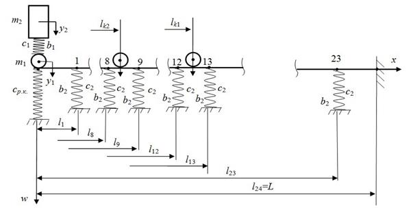
Fig. 6. Diagram of rail sections in the third phase of movement
Considering equations (8) and (10), as well as the diagram in Figure 6, we obtain:
at a section ![]() :
:
at a section ![]()
![]() і
і ![]()
at a section ![]()
![]() і
і ![]()
 (11)
(11)
at a section ![]() і
і ![]()
![]()
 (12)
(12)
In this case, we will have 31 variables: ![]() ,
, ![]() ,
, ![]() ,
, ![]() ,
, ![]()
![]() ,
, ![]() ,
, ![]() ,
, ![]() ,
, ![]() .
.
Next,
we determine the eigenfrequencies ωs
with respect to solutions (6) and the initial conditions of the mechanical
system in Figure 6, which we will additionally include equalities in:
![]() ;
;
![]() ;
;
![]() ;
;
![]() .
.
The orthogonality conditions of the system in the third phase of motion then takes the following form:
 (13)
(13)
Consequently, we obtain the following expressions for
determining the constants Ms,
Ds of motion equations (when ![]() and
and ![]() ):
):
 ;
(14)
;
(14)
where ![]() and
and ![]() , when
, when ![]() ,
, ![]() ,
,
 (15)
(15)
Finally, the deflection of the facing rail in the third phase of the tramcar’s movement will be determined by the expression:
![]() .
(16)
.
(16)
At stage 2 of the method, the actions of static Р0 and inertial m1 loads with coordinates lk1, lk2 are additionally considered.
At stage 3 of the method, the deflection of the receiving rail under the first sleeper in the third phase of the tramcar movement will be determined by the formula:
![]() .
(17)
.
(17)
Here ![]() , it is determined by the data of Section 3.1 of this
article.
, it is determined by the data of Section 3.1 of this
article.
Analysis of these calculations shows that:
1) change in the tramcar load
when ![]() kg with motion speed
kg with motion speed ![]() m/s leads to a change in the dynamic deflection of the
facing rail under the first sleeper in the range
m/s leads to a change in the dynamic deflection of the
facing rail under the first sleeper in the range ![]() mm, that is, to its growth of 1.9 times;
mm, that is, to its growth of 1.9 times;
2) it is determined that the
increase in the speed of a tramcar in the range of ![]() m/s when loading a tramcar
m/s when loading a tramcar ![]() kg leads to the amount change in the deflection in the
range
kg leads to the amount change in the deflection in the
range ![]() mm, that is, to its growth of 1.89 times.
mm, that is, to its growth of 1.89 times.
The results obtained are used when solving the issue of improving the upper structure of the rail track, as well as in determining the safe operating modes of tramcars.
4. RESEARCH RESULTS
In this paper, based on the improved
dynamic model that describes the deflections of the facing rail, considering
the characteristics of rigidity and damping of the suspension of the tramcar
and the ballast layer, the speed, loading and phase of movement of the tramcar
through the current number of reduced masses of wheels on the rail, it was
possible to calculate the parameters of post-impact interaction in the
mechanical system "tramcar-rail track" at the phase of growth of
deflections under the first sleeper.
A method of sequential static-impact-dynamic calculation of
deflections of the facing rail under the first sleeper in the growth phase was
developed. This made it possible to note the phases of movement of the tramcar
relative to the joint irregularity,
its loading and speed, as well as the boundary conditions for fixing the facing
and trailing rails, geometric and mechanical characteristics of rails and butt
linings, sleepers and ballast layer. The method provides opportunities for
studying the processes of mechanical interaction of a tramcar and a rail track
aimed at improving the operating modes of the vehicle, as well as the upper
structure of the track.
The dependences of static, impact and generalised components of the height of joint irregularity at the growth stage on the phases of movement of the tramcar are obtained. This was done taking into account the orthogonality of the vibrations forms of the facing rail, the operational, structural and mechanical characteristics of the tramcar and the upper structure of the track. Thus, allowing determining whether the maximum deflections of the receiving rail under the first sleeper belong to the range of acceptable values of elastic deformations, which are set by the regulatory document. This paper suggests using the mechanical interaction of a tramcar with a rail track in the joint zone as a normative factor – the deflection of the receiving rail under the first sleeper. Loads on the ballast layer of the upper track structure are caused by deflections of the track rails. They are affected by the operational, mechanical and geometric parameters of the vehicle, rails, butt linings, sleepers and ballast layer. Following the standards of operation of electric transport, the pressure transmitted from the sleeper to the ballast layer should not exceed the maximum permissible value, which, for example, in summer is equal to [σ] = 19.62 N/cm2. In real operating conditions, an informative parameter that will characterise the mechanical interaction of the car with the rail track in the joint area, which is derived from the pressure factor on the ballast layer and can be measured by external controls, is the deflection of the sleeper. The generalised deflection of the rail, which corresponds to the standard maximum permissible pressure, depends on the specific area and weight of the sleeper, the specific weight of the rail and the stiffness of the ballast layer. It is known that the most important generalised deflection occurs under the first sleeper of the receiving rail. In general, the value of the specified deflection must satisfy irregularities that do not contradict the standard condition for not exceeding the maximum permissible pressure.
5. CONCLUSIONS
The numerical calculation results for the parameters of
the mechanical railway
rolling stock – track interaction in the area of joints are given.
The analysis is based on the integral model, which considers operational,
mechanical, and geometric factors. This approach allows establishing new
patterns of interaction between the four-axle car and the track while passing
over joint irregularity, as well as to improve the operational parameters, car
characteristics and the upper structure of the track by rational selection and
optimisation.
The model proposed can be used
in the development of design solutions for improving the rail track joint,
determining the operating modes of tramcars depending on the type of rail
track, creating an experimental and theoretical complex for studying, calculating
and improving the parameters of rail transport knots. All of this makes it possible to take a significant step
in the development of electric transport towards a more environmentally
friendly, safe, convenient and economical way to transport passengers and
cargo.
References
1.
Вериго М.Ф., А.Я. Коган. 1986. Взаимодействие
пути и
подвижного
состава.
Москва:
Транспорт. 559 с. [In Russian: Verigo M.F., A.Ya. Kogan. 1986. Interaction of track and rolling stock.
Moscow: Transport. 559 p.].
2.
Auersch L., S. Said. 2021. „Dynamic
track-soil interaction-calculations and measurements of slab and ballast
tracks”. Journal of
Zhejiang University - Science A: Applied Physics & Engineering 22(1): 21-36. DOI: https://doi.org/10.1631/jzus.A1900651.
3.
Даренський
О.М.,
А.В. Клименко. 2013. „Моделирование взаимодействия пути и подвижного состава при дискретном подрельсовом основании в зоне рельсовых стыков”. Інформаційно-керуючі
системи на
залізничному
транспорті 4: 15-22. [In Ukrainian: Darensky O.M., A.V. Klimenko. 2013. „Simulation
of the interaction of the track and rolling stock at a discrete sub-rail base
in the area of rail joints”. Information
and control systems in railway transport 4: 15-22].
4.
Манашкин
Л.Я., С.В. Мямлин,
В.И. Приходько. 2008. „Оценка
силы
ударного взаимодействия
колеса и
рельса на
стыке двух
рельсов”. Вісник
Дніпропетровського
національного
університету
залізничного
транспорту імені
академіка В.
Лазаряна 22: 36-39. [In Ukrainian: Manashkin
L.A., S.V. Myamlin, V.I. Prihodko
. 2008. “Otsenka silyi udarnogo vzaimodeystviya kolesa i relsa na styike
dvuh relsov”. Visnik
Dnipropetrovskogo natsionalnogo universitetu zaliznichnogo transportu Imeni
akademika V. Lazaryana 22: 36-39]. Available at: http://nbuv.gov.ua/UJRN/vdnuzt_2008_22_10.
5.
Sun
Y., C. Cole, M. Spiryagin. 2013. “Study on track dynamic forces
due to rail short-wavelength dip defects using rail vehicle-track dynamics
simulations”. Journal of Mechanical Science and
Technology 27(3): 629-640. DOI: https://doi.org/10.1007/s12206-013-0117-8.
6.
Auersch L. 2021. „Train-induced ground vibration due to the irregularities of
the soil”. Soil Dynamics and
Earthquake Engineering 140. DOI: https://doi.org/10.1016/j.soildyn.2020.106438.
7.
Кузьмицкий
Я.О., Д.В.
Шевченко, А.К. Беляев.
2015. ”Конечно-элементное
моделирование
процесса
перекатывания
колеса через
стык”. Научно-технические
ведомости
СПбГПУ 4(23): 170-178. [In Russian: Kuzmickij Ja. O., D.V. Shevchenko, A.K.
Beljaev. 2015. “Finite element modeling of the wheel rolling process through
the joint”. Nauchno-tehnicheskie
vedomosti SPbGPU 4(23): 170-178]. DOI: https://doi.org/10.5862/JEST.231.18.
8.
Jasiulewicz-Kaczmarek
M., K. Antosz, P. Żywica, D. Mazurkiewicz, B. Sun, Y. Ren. 2021. „Framework
of machine criticality assessment with criteria interactions”. Eksploatacja i Niezawodnosc –
Maintenance and Reliability 23(2): 207-220.
9.
Иванов
М.Д., А.А. Пономарев, Б.К. Иеропольский.
1977. Трамвайные вагоны Т-3. Москва: Транспорт. 240 с. [In Russian: Ivanov
M.D., A.A. Ponomarev, B.K. Ieropolsky. 1977. Tram cars T-3. Moscow: Transport. 240 p.].
10. Бабаков И.М. 1968.
Теория колебаний. Москва:
Наука. 691 с. [In Russian:
Babakov I.M. 1968. Theory of
oscillations.
Moscow: Science. 691 p.].
Received 18.09.2021; accepted in
revised form 04.11.2021
![]()
Scientific Journal of Silesian University of Technology. Series
Transport is licensed under a Creative Commons Attribution 4.0
International License