Article citation information:
Konieczny, J. Destruction
mechanisms of Cu-ETP copper guides for sectional insulators of railway traction.
Scientific Journal of Silesian University
of Technology. Series Transport. 2021, 113,
101-113. ISSN: 0209-3324. DOI: https://doi.org/10.20858/sjsutst.2021.113.8.
Jarosław KONIECZNY[1]
DESTRUCTION MECHANISMS OF CU-ETP COPPER GUIDES FOR SECTIONAL INSULATORS
OF RAILWAY TRACTION
Summary. This article
presents the results of a research on the operational damage to sectional
insulator guides made of hard electrolytic copper Cu-ETP (Electrolytic Tough
Pitch Copper). The guides were used on various rail routes, in real conditions,
on which the trains ran at maximum speeds between 40 and 120 km/h for
periods of 6 or 12 months. The microstructure of the surface, the working
layer of the guide, which contacts the graphite plate of the current collector
and the cross-section of the guide in the place where it was damaged was
examined using the Olympus light microscope. The analysis of the chemical
composition in the EDS micro-regions was performed using the Zeiss Supra 53
scanning electron microscope (SEM), while the qualitative X-ray phase analysis
was performed with the use of the Panalytical X'Pert diffractometer. Scratches
and deformations of the surface layer characteristic of the phenomenon of
friction caused by the current collector were observed in the microstructure of
the damaged parts of the guides of section insulators. The effect of a very
intense oxidation process was also observed, as well as the effects of an
electric arc, which according to the author, is the factor that has the most
destructive effect on the condition of the guides.
Keywords: microstructure,
wear mechanisms, electric traction, guide, section insulator
1.
INTRODUCTION
The contact of the current collector –
damages the guide as a result of tribological mechanisms (abrasion, abrasive
wear of the working surface). While the train is moving, a cloud of dust and
fine particles of the rail bed material as well as the transported materials,
for example, coal, sand and other aggregates are stirred up as a result of a
blast of air generated by the fast-moving rolling stock. The excited fine
particles settle on the traction lines or get between the working surfaces of
the current collector and the guide and act as an additional abrasive medium.
Moreover, the difference in the potentials of the two adjacent railway traction
sections causes an electric arc to be generated during the jump of the
pantograph from one guide rail to another [3]. The temperature of an electric
arc in its centre can be as high as 20,000°C [4, 5]. The initiation of an
arc and the generated temperature causes the metal elements close to the arc to
become plasticised or even melted. The guide material is copper Cu-ETP (Table
1), the melting point of which is 1,083°C [6]. The plasticised guide
deforms under the pressure of the pantograph, leading to its further
destruction. In an electric arc, small local discharges are generated,
resulting in small craters burned in the guide.
This publication presents damage to the
guides of section insulators which is the result of their operation in real
conditions.
2. MATERIALS AND METHODS
The chemical composition of Cu-ETP copper, from which the guides of the section insulators subject to the tests were made, is presented in Table 1.
Tab. 1
Approximate chemical
composition of copper Cu-ETP
(based on standards [7, 8])
|
Type of copper |
The maximum concentration of elements, % |
|||||
|
Cu |
Ag |
O |
Bi |
Pb |
Other, in total |
|
|
Cu-ETP |
99.9 |
0.015 |
0.04 |
0.0005 |
0.005 |
0.03 (without Ag, O) |
An X-ray phase analysis was performed using the Panalytical X'Pert diffractometer using filtered radiation from a cobalt anode lamp. The measurement step was 0.05, and the impulse counting time was 10 s.
The samples cut out from the used guides were incorporated in epoxy resin, then sanded with sandpaper of progressively finer grit. The previously prepared specimens were polished with the Al2O3 suspension, which was replaced with a diamond suspension with a grain size of 1 μm. The specimens were then etched in a solution of: 2 g of potassium chromate K2Cr2O7, 100 cm3 of distilled water, 4 cm3 of sodium chloride NaCl solution, 8 cm3 of sulfuric acid H2SO4. The specimens were subjected to multiple alternating polishing and etching to obtain the proper images of the microstructure.
The metallographic specimens were examined using the Olympus light microscope with magnifications of 50, 100, 200, 500, 1000, 2000x.
The Zeiss Supra 25 scanning electron microscope (SEM) was used to perform the microstructure examination employing the EDS method.
3. RESULTS
Given the observations on a macro scale, it was found that the greatest wear, as well as the deformation of the working surface, occurred in the immediate vicinity of the beginning of the arcing horn of the guide (Figure 1).
Given the measurement of the length of the abrasion marks on the guides of the section insulator, it was found that with the increase in vehicle speed (current collector), the length of the marks decreased. For the maximum speed of 40 km/h (the guide used for 12 months), the length of the abrasion mark is 75 mm (P1), for the speed of 120 km/h (the guide used for 12 months), it is 35 mm (P2) and for 120 km/h (the guide used for 6 months), it is only 25 mm (P3) (Figure 2).
![]()

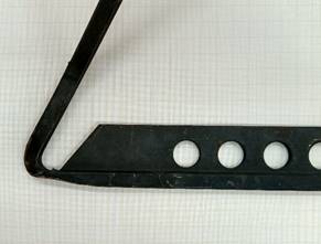
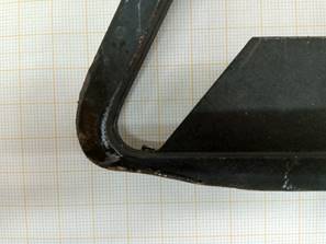
Fig. 1.
Guide of the section insulator at the beginning of the horn extinguishing
an electric arc. a) a new unused element; b) an element operated with a visible
defect
The relation shown in Figure 2 can be explained by the
fact that the sliding speed is an important parameter influencing the process,
which takes place between the copper-graphite elements. As it results from the
research [9], both the friction coefficient and the degree of wear increase at
low speeds. Increasing the sliding speed to moderate speeds reduces the
friction, and consequently, the wear decreases.
The article [10] investigated the mechanisms of
premature tribological wear between the contact strip made of copper and the
copper wire used as a railway line with the use of a graphite layer on the wire.
It was noticed that because of exploitation, wear debris was present between
the mating elements (copper oxides Cu2O and hardened copper).
Additionally, the presence of hard abrasive particles such as SiO2
and Al2O3 was found. These particles, which most likely
got between the mating elements from the outside, intensify the abrasion
process. In all investigated regions without apparent wear, with
moderate wear and severe wear, based on the nature of the cracks of the
surface, it was found that they were caused either by work hardening or thermal
cycle. A material detachment and production
of hard abrasives were also frequently noticed. A material detachment (on a
macro scale) was also found in this article. The presence of a copper oxide
layer, which was formed in the copper wire and acid-resistant steel type 18-8
couple, was also found in the article [11].
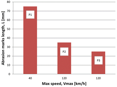
Fig. 2. Change in the length of the abrasion marks on
the guide depending on the maximum speed of the locomotive, P1 - 40
km/h, 12 months, P2 - 120 km/h, 12 months, P3 - 120 km/h, 6 months
The guide which had been damaged as a result
of operation was cut and a cross-section was mounted in the epoxy resin (Figure
3). Considering the macroscopic observations, it was found that the working
surface of the guide, due to exploitation, was worn and formed in a shape of a
so-called 'cradle' (1). On both sides are visible 'whiskers' (2) – made
by plasticised material of the
guide and then by the pressure of the current collector.
The microstructure in the area of the geometric centre of the
cross-section (3) and the deformed 'whiskers' (2) are shown in Figure 4. Figure
4a shows the microstructure of copper, which is characteristic of a
non-plastically deformed material with a predominant amount of equiaxed grains, with a shape similar to a sphere. Figure 4b shows the
microstructure grains with an elongated shape close to axial, showing the
mechanism and direction of the deformation. The average grain size (diameter)
of the microstructure shown in Figure 4a is 14.9 µm with a standard
deviation of 6.2 µm (41.6% of the average value), whereas, for the microstructure
shown in Figure 4b, it is 7.1 µm with a standard deviation of 4.3
µm (60.5% of the average value). The presented data show that the plastic
deformation in the 'whiskers' (2) resulted in a reduction of the grain size by
over 50%, and the increase in the value of the standard deviation indicates an
increasing difference in grain size.
(3) (2) (2) (1)![]()
![]()
![]()
![]()
Fig.
3. Cross-section of the guide in the area marked in Figure 1B
b) a)
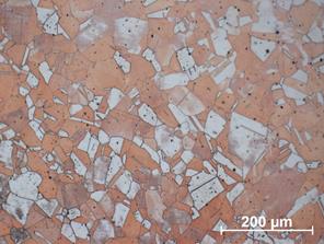

Fig. 4.
Microstructure of the cross-section of the Cu-ETP copper guide; a) central area
of the section;
b) deformed ‘whiskers’
In the next stage of the research, it was verified whether the working surface
of the guide, apart from the deformation of its shape, was not permanently
contaminated, as that could reduce the electrical conductivity in the contact
between the guide and the current collector and also enhance corrosion
processes. Thus, a qualitative X-ray phase analysis was applied.
In the structure of the material of a new guide of the section
insulator made of Cu-ETP copper (Figure 5), only the presence of copper was
confirmed based on the qualitative X-ray phase analysis, which was expected.
However, in the case of a guide that had been used for 12 months on a railway
line, where the trains travelled at the maximum speed of 120 km/h, apart from
copper, the presence of copper oxide Cu2O was found (Figure 6),
which was confirmed by the reflections from the planes (111), (002), (022) and
(113) of this phase. These results prove that during the operation
of the guide, copper oxide was released on its surface. This is because the
flow of electric current produces a thin layer of oxides, which may also play a
positive role as a lubricant on the contact surface [9, 12]. The thin oxide
layer formed on the contact surface excludes direct contact and reduces the
adhesion between the elements. According to some scientists [13, 14], the oxide
layer formed by the electric current on the contact surface of mating elements
plays a major role in reducing the coefficient of friction. However, the
authors [10, 15, 16] suggest that the flowing electric current works as a
lubricant in the pulling process at constant parameters.
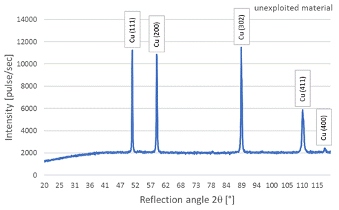
Fig. 5. Diffractogram of a new guide
The thickness of
the oxide layer which is released as a result of the flowing electric current
can be determined using the following equation [17]:
![]() (1)
(1)
Rc – contact
resistance,
qc – electrical
resistance of copper,
q0 – electrical
resistance of a thin layer of copper oxide,
X – thickness
of the copper oxide layer,
a – radius of
the circle corresponding to the total contact area.
An unfavourable effect of the current flow through the
railway line during the friction process is the increase in the contact
temperature of the copper-graphite couple.
In the experiment performed by [18], the contact
temperature of the materials increased sharply at the beginning of the
experiment and became stable after about 20 minutes for the current of 0, 10,
20 or 30 A. The stabilisation of the
temperature is slower when the current increases and for 50 A it takes place
only after 50 minutes. The contact temperature of the tribological couple
increased with the increase in the applied electric current. The contact
temperature of the friction couple without the applied electric current was
about 40°C, and for the maximum value of the applied electric current (I =
50A), the temperature was much higher and was about 115-120°C. Similar
results were described in the article [16]. Further, It was found that the
synergistic interaction of Joule's heat, the heat caused by friction and arc
discharge, leads to a rapid increase in the contact temperature [19]. Hence, it
follows that a locomotive, which moves with a heavy freight train, due to the
intense consumption of electricity from the railway line, makes such line most
vulnerable to damage.
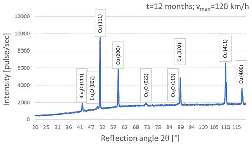
Fig.
6. Diffraction pattern of the guide after 12 months of operation on the route
with a maximum train speed of 120 km/h
The increase in temperature on the surface adversely
affects the properties of copper. It is conducive to oxidation [6]. Figure 7
shows the dependence of the increase in the volume of copper oxides on its
surface with the time and temperature of exposure. With the increase in
temperature to 70°C, the volume of oxides increases more than four times
compared with the temperature of 20°C after 600 minutes of exposure and five
times after 1000 minutes. Moreover, the composition, size and nature of the
debris consisting of oxides formed on the contact surface affect the friction
between the friction elements, and thus, the nature of the couple's operation
[20].
Oxidation
occurs by diffusion of oxygen ions into the interior of the metal and sometimes
by metal ions, which diffuse out of the rough surfaces. When the oxide layer
reaches a critical thickness, it becomes unstable and disintegrates. Such
exposed unoxidised surface may re-oxidise [21].
Thereafter, the microstructure of the guide's
working surface was examined using a scanning electron microscope. The
examination revealed abrasion marks visible on the surface caused by sliding
and friction of the current collector on the surface of the guide during
operation. The scratch lines are visible in the photo and run from left to
right (Figure 8) following the working direction of the pantograph. An area of
the base material was also noticed, which was torn off as a result of
exploitation, and then, due to successive slides of the pantograph (current
collector), glued/pressed with the guide base material in the contact place. A
detachment of the base material due to friction was also observed in [10].
The detachment of a part (volume) of the
material may also be caused by the plastification of the material due to a
sudden increase in temperature from an electric arc. Because the pressure force
of the current collector is not big enough to cause the effect shown in Figure
8 without the influence of temperature.
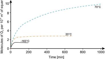
Fig.
7. Effects of temperature on oxidation of copper [6]
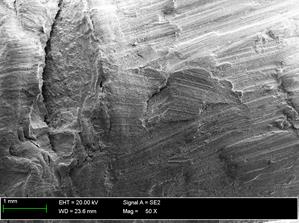
Fig.
8. Microstructure of the working surface of P2 sample (120 kph for 12 months)
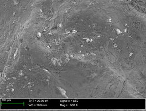
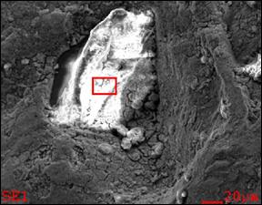
The next step in the analysis of the failure
mechanisms of the section insulator guide was the analysis of intensity as a
function of energy-dispersive X-ray spectroscopy (Figure 9). Burned craters
were noticed in the microstructure of the surface of the guide. The analysis of
the chemical composition in the micro-areas confirmed the presence of carbon,
oxygen, silicon and copper as well as small amounts of iron, sulfur, aluminium,
phosphorus and chlorine (Figure 9c). A large amount of oxygen indicates
the presence of oxides. The reason for such a large increase in oxides is most
likely the phenomenon of an electric arc generated during the jump of the
current collector between the guides of neighbouring sections of the railway
traction. An arc usually occurs as a result of the distinct potential
differences between the neighbouring sections. The temperature in the centre of
an arc may rise to several thousand degrees Celsius [22]. The presence of
oxides on the examined surface is evidenced by numerous bright areas in the
photo (Figure 9a, b) caused by the lack of electrical conductivity of the
electron beam forming the image in the electron microscope. The particle shown
in Figure 9b can also be a grain of sand, which was pulled in the gust of the
moving train, then got between the surfaces of the current collector, softened
by the high temperature of the electric arc of the guide and finally pressed
into the guide. The large increase in temperature also generated local melting
of the basic material and its subsequent rapid cooling caused numerous
stresses, leading to local cracks in the material of the guide (Figure 9b).
burned crater crack b) a)
![]()
![]()
![]()
![]()
c)
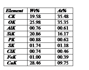
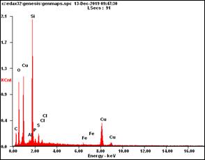
Fig. 9.
Microstructure of surface of P2 sample (120 km/h for 12 months) (a, b)
and analysis of the chemical composition of
the marked area (c)
The effect of an
electric arc on the copper guide is shown in Figure 10. In the upper part of the
guide's cross-section (Figure 10a), a melted area of the material is visible,
whereas, below there is a transition zone and then the microstructure of the
Cu-ETP guide. Some grains are visible in the microstructure.
Figure 10b,
which is a top view of the guide's working surface, on the left can be seen a
melted area and on the right side, there is a groove carved by the current
collector. The geometrical features of the groove indicate that it could have
been carved by foreign particles, that is, sand grains that got between the
working surface of the guide and the current collector. The melted layer of the
vitrified material of the guide is interspersed with holes from which gases
escaped during melting. The nature of these damages clearly indicates surface
erosion caused by an electric arc. A negative effect, which an electric arc has
on the elements of the railway traction, is the significant porosity of the
melted metal. The pores can be penetrated by pollutants or water from
precipitation, which may constitute local corrosion centres. Moreover, the
metal melted in such conditions is characterised by unfavourable
mechanical properties and reduced resistance to frictional wear. As earlier
indicated, the oxide layer grows to a critical thickness, and then separates
from the base material, revealing a non-corroded material layer, which may
oxidise again [21].
Depending on the
parameters of the current, an electric arc consists of many separate,
simultaneous discharges. Because the typical spot size is within the sub-micron
range, local melting causes characteristic craters. The arc jumps from one
place to another with a greater likelihood of ignition near the craters of
previous arcs. Eventually, macroscopically visible traces are formed,
consisting of many craters with a micron range [23, 24].
Fig.
10. Microstructure: (a) of the cross-section of the guide,
(b) of the working surface of
the guide
Arc
erosion also depends on the cleanliness of the surface [24]. An electric arc
can move quickly and remove only the surface layer of the material or cause
erosion of the material. Erosion is the result of an arc plasma that consists,
among others, of ions of the material and due to high temperature causes
melting or even evaporation of the surface material [25]. The melted material
can only move a few microns. In this way, craters are formed or the material is
scattered by the pressure of droplets, which form the arc plasma [26].
The ignition
of an electric arc occurs when the actual local electric field strength exceeds
the critical field strength. This value, characteristic for a given place,
depends, among others, on the material of the cathode, the surface geometry in
nano- and microscale, as well as on dielectric layers and solid particles. The
ignition is much easier when dielectric layers and 'contaminants' are present
on the surface so that more spots can ignite and operate in parallel,
electrically competing for available power. In the absence of field enhancing
dielectrics, ignition is less likely, and the power is concentrated in a small
number of fragments [24].
The
article [27] states that the normal load is one of the main controlling factors
for the generation of an electric arc during the friction process of the
copper/graphite coupled with the electric current applied. The strength of an
electric arc is enhanced with the decrease of normal loads and the increase of
electric currents. At lower normal
loads (Fn ≤1.0 N) during tests with applied electric current, the
friction process is unstable, and the friction coefficient fluctuates quite
strongly due to the appearance of an electric arc.
An electric arc burning in the
air is characterised by
high temperature [5, 22], high current density and a small voltage drop along
its length. An electric arc in the air does not limit its length only to the
space between the electrodes, but it elongates under the influence of the force
generated by its own electromagnetic field. One of the effects of an electric
arc is an accompanying pressure shock wave, which rapidly heats the air along
the arc axis. Consequently, a hot stream of gases lifts melted metal particles
from the surface of the conductor [4].
4.
CONCLUSIONS
The guides of section insulators are made of
Cu-ETP copper, and during operation, they wear out because of several
mechanisms. Based on the analysis of the presented research results, it can be
concluded that:
· friction, corrosion (oxidation of copper) and
an electric arc constitute the mechanisms responsible for damage of the guides;
· corrosion depends on the process of
diffusion, which is thermally activated, and its intensity increases with the
increase of energy, the presence of an electric arc will significantly
accelerate it;
· the results of microscopic examinations
clearly show that the dominant wear/destruction mechanism of the guides is an
electric arc, and the damages are its consequences. The increase in temperature
in the centre of an electric arc, which according to the literature data, can
reach even 20,000°C [5, 22], is the factor responsible for the greatest
damage to the guide. Since the action of this factor is very short (a few
hundredths of a second), the damage to the guide may not be visible in a short
time;
· the
increase in temperature at the interface between the guide and the current
collector caused by both friction and Joule heating adversely affect the
properties of the copper. It is conducive to the oxidation phenomenon, and the
composition, size and nature of the oxidation products have an impact on the
friction phenomenon, and thus, on the nature of the mating of the guide-current
collector couple [20];
·
thermal
wear, arc erosion and abrasive wear are the dominant wear mechanisms, which
take place in the process of sliding friction in the flow of electric current
that accompanies the transfer of material [13];
· contamination on the contact surface of the guide with
the current collector and changing the guide geometry may facilitate the
ignition of an electric arc [24].
References
1.
Załącznik
do zarządzenia Nr 14/2010 Zarządu PKP Polskie Linie Kolejowe S.A. z
dnia 10 maja 2010 r. Wytyczne projektowania, budowy i odbioru sieci trakcyjnej
oraz układów zasilania 2×25 kV AC dla linii kolejowych o
prędkości do 350 km/h Iet-6. [In Polish: Annex
to the order No. 14/2010 of the Management Board of PKP Polskie Linie Kolejowe
S.A. of 10 May 2010. Guidelines for the design, construction
and acceptance of the overhead contact line and 2 × 25 kV AC power supply
systems for railway lines with a speed of up to 350 km/h Iet-6]. P. 88. Available
at:
https://www.plk-sa.pl/files/public/user_upload/pdf/Akty_prawne_i_przepisy/Instrukcje/Wydruk/Iet-6.pdf.
2.
BN-769317-109. Sieć
trakcyjna kolejowa. Izolatory
sekcyjne. Warszawa: Centralny Ośrodek Badań i Rozwoju Techniki Kolejnictwa/Instytut
Kolejnictwa. [In Polish: Railway traction
network. Section insulators. Warsaw: Central Research and Development
Center of Railway Technology/Railway Research Institute].
3.
Szeląg
Adam. 2005. “Problemy oddziaływania trakcji elektrycznej na
środowisko”. Technika Transportu Szynowego 11-12: 46-57.
ISSN: 1232-3829. [In Polish: “Problems of the
influence of electric traction on the environment”].
4.
Gierlotka
Stefan. 2008. „Łuk elektryczny i skutki jego działania na
człowieka”. Elektro Info 9: 100-102. ISSN: 1642-8722. [In
Polish: „Electric arc and its effects on humans”].
5.
Kano
Ryota, Nemoto Yusuke, Maeda Yoshifumi, Yamamoto Shinji, Iwao Toru. 2020.
„Arc temperature measurement with microsecond spectroscopic
measurement”. Electrical Engineering in Japan 210: 29-36. ISSN:
0424-7760. DOI: https://doi.org/10.1002/eej.23259.
6.
Chapman
David, Toby Norris. 2014. Copper for Busbars. Copper Development
Association Publication No 22. Available at: https://leonardo-energy.pl/wp-content/uploads/2016/09/EIM6105-Szynoprzewody-wykonane-z-miedzi-poradnik-ang.pdf.
7.
PN-EN
1976:2013-04. Miedź i stopy
miedzi. Wyroby odlewane z miedzi nie przerobione plastycznie. Warszawa: Polski
Komitet Normalizacyjny. [In Polish: PN-EN 1976:2013-04. Copper and copper
alloys. Copper-cast
products not wrought. Warsaw: Polish Committee of
Standardization].
8.
PN-EN 1652:1999. Miedź i stopy
miedzi. Płyty, blachy, taśmy i krążki ogólnego
przeznaczenia.
Warszawa: Polski
Komitet Normalizacyjny. [In Polish: PN-EN
1652:1999. Copper and copper alloys.
General purpose plates, sheets, strips and
pulleys.
Warsaw: Polish Committee of Standardization].
9.
Benfoughal
Abdeldjalil, Ali Bouchoucha, Youcef Mouadji. 2018. “Effect of electrical current on friction and
wear behavior of copper against graphite for low sliding speeds”. UPB
Scientific Bulletin, Series D: Mechanical Engineering 80(3): 117-130.
ISSN: 1454-2358.
10. Azevedo Cesar
R.F., Amilton Sinatora. 2004. “Failure analysis of a railway copper
contact strip”. Engineering Failure Analysis 11: 829-841. ISSN:
1350-6307. DOI: https://doi.org/10.1016/j.engfailanal.2004.03.003.
11. Senouci
A., H. Zaïdi, J. Frêne,
A. Bouchoucha, D. Paulmier. 1999. „Damage of
surfaces in sliding electrical contact copper/steel”. Applied Surface
Science 144-145: 287-291. ISSN: 0169-4332. DOI:
https://doi.org/10.1016/S0169-4332(98)00915-5.
12.
Wang Yian A., Lin Jinxu X., Yan Yu, Qiao Lijie J.
2012. “Effect of
electrical current on tribological behavior of copper-impregnated metallized
carbon against a Cu-Cr-Zr alloy”. Tribology International 50:
26–34. ISSN: 0301-679X. DOI: https://doi.org/10.1016/j.triboint.2011.12.022.
15.
Guangxiong X.FengxueMinghao H.Friction and wear behaviour of stainless steel
rubbing against copper-impregnated metallized carbon”. Tribology
International 42(6): 934-939. ISSN: 0301-679X. DOI: https://doi.org/10.1016/j.triboint.2008.12.011.
16.
Zhao
Han, Barber Gary C., Liu J. 2001. “Friction and wear in high speed sliding with and without
electrical current”. Wear 249(5-6): 409-414. ISSN:
0043-1648. DOI: https://doi.org/10.1016/S0043-1648(01)00545-2.
17.
Holm
Ragnar. 1967. Electric Contacts. Fourth
ed. Berlin: Springer. ISBN: 978-3-540-03875-7.
18.
Ding Tao, Chen Guangxiong, Bu Jun, Zhang Weihua. 2011.
“Effect of temperature and arc discharge on friction and wear behaviours
of carbon strip/copper contact wire in pantograph–catenary
systems”. Wear 271: 1629-1636. ISSN: 0043-1648. DOI: https://doi.org/10.1016/j.wear.2010.12.031.
19.
Filice
Luigino, Fabrizio Micari, Stefania Rizzuti, Domenico Umbrello. 2007. „A
critical analysis of the friction modeling in orthogonal machining”. International
Journal of Machine Tools & Manufacture 47: 709-714. ISSN: 0890-6955.
DOI: https://doi.org/10.1016/j.ijmachtools.2006.05.007.
20.
Bouchoucha Ali, Said Chekroud, Daniel Paulmier. 2004.
“Influence of the electrical sliding speed on friction and wear processes
in an electrical contact copper – stainless steel”. Applied
Surface Science 223: 330-342. ISSN: 0169-4332. DOI: https://doi.org/10.1016/j.apsusc.2003.09.018.
21.
Bouchoucha
A., E.K. Kadiri, F. Robert, H. Zaïdi, D. Paulmier. 1995. „Metals
transfer and oxidation of copper-steel surfaces in electrical sliding contact”.
Surface and Coatings Technology 76-77:
521-527. ISSN: 0257-8972. DOI: https://doi.org/10.1016/0257-8972(95)02603-7.
22.
Szadkowski
Marek. 2016. Zagrożenie
porażeniem łukiem elektrycznym w instalacjach nn I SN. Stowarzyszenie
Elektryków Polskich o. Tarnów [In Polish: Electric arc hazard in LV and MV
installations. Association of Polish Electrical Engineers, Tarnów].
Available at: http://www.sep-tarnow.com.pl/files/Zagrożenie
porażeniem łukiem-elektrycznym w instalacjach-nn-i.pdf.
23.
Jüttner
Burkhard. 2001. „Cathode spots of electric
arcs”. Journal of Physics D: Applied Physics 34: R103. DOI:
https://doi.org/10.1088/0022-3727/34/17/202.
24.
Anders
André. 2005. „The fractal nature of vacuum arc cathode
spots”. IEEE Transactions on Plasma Science 33(5): 1456-1464. ISSN:
0093-3813. DOI: https://doi.org/10.1109/TPS.2005.856488.
25.
Daadler
J.E. 1981. „Cathode spots and vacuum arcs”. Physica
B+C 104(1-2): 91-106. ISSN: 0378-4363. DOI:
https://doi.org/10.1016/0378-4363(81)90040-1.
26.
Rohde
Volker, Martin Balden. 2016. „Arc erosion of full metal plasma facing
components at the inner baffle region of ASDEX Upgrade”. Nuclear
Materials and Energy 9: 36-39. ISSN: 2352-1791. DOI:
https://doi.org/10.1016/j.nme.2016.09.006.
27.
Lin Xiu-Zhou, Min-Hao Zhu, Ji-Liang Mo, Guang-Xiong Chen, Xue-Song
Jin,
Zhong-Rong Zhou. 2011. „Tribological and electric-arc behaviors of
carbon/copper pair during sliding friction process with electric current
applied”. Transactions of
Nonferrous Metals Society of China 21: 292-299. ISSN: 1003-6326. DOI: https://doi.org/10.1016/S1003-6326(11)60712-7.
Received 03.10.2021; accepted in
revised form 20.11.2021
![]()
Scientific Journal of Silesian University of Technology. Series
Transport is licensed under a Creative Commons Attribution 4.0
International License