Article citation information:
Jírová,
R., Pešík, L. Pneumatic vibroisolation system of the base desk with natural
frequency regulation. Scientific Journal
of Silesian University of Technology. Series Transport. 2021, 113, 91-100. ISSN: 0209-3324. DOI: https://doi.org/10.20858/sjsutst.2021.113.7.
Radka JÍROVÁ[1], Lubomír PEŠÍK[2]
PNEUMATIC VIBROISOLATION SYSTEM OF THE BASE
DESK WITH NATURAL FREQUENCY REGULATION
Summary. Vibroisolation systems of base desks for machine and
testing facilities usually cannot effect efficient changing of their own
frequencies according to operating conditions. Especially in the case of the
automotive industry, the possibility of changing natural frequencies is
very desirable. During varying operating conditions, the vibroisolation
system needs to be regulated easily and quickly regarding the minimisation of
dynamical forces transmitted to the ground and to ensure the stability of the
testing process. This paper describes one of the options of tuning the base
desk at a relatively short time and by sufficient change of own frequencies,
which decides the dynamical behaviour of the whole system.
Keywords: pneumatic
suspension, base block suspension, testing facility susp
1. INTRODUCTION
Many testing laboratories of mechanical devices and transport facilities use base blocks assembled to the ground through elastic and damping connections [1, 2]. The elastic connection is usually achieved by pneumatic springs that enable facile regulation of static height. They also ensure low natural frequencies of dynamical systems, which is often desirable in the service of the testing laboratory. By increasing of pneumatic springs load for getting the required static height, their stiffness increases too. On the contrary, natural frequencies roughly remain at the same level. On base blocks, different testing facilities are operated, and it is not always possible to place these facilities near the geometry centre of the block. Thus, an asymmetry of mass distribution to the elastic connection appears. In addition, the position of the centre of elasticity is changed. The asymmetry of inertia, exciting and reaction spring forces leads to moment loading and tilting of the base block. This situation may affect the methodology of testing and the results of measurements as well. Therefore, the modification of elastic connections of the base block is needed. One of the possible solutions is proposed and described in this article.
2. SUSPENSION OF THE BASE BLOCK
For saving space or by installation, testing facilities to higher floors of a building, base blocks are designed as reinforced cast iron without increasing of mass inertia through an additional reinforced concrete block. The suspension system is then composed of the huge base block suspended by pneumatic springs that are divided into three sections: P1, P2 and P3. Each section is connected to a regulator of static height R1, R2 and R3. Pneumatic springs in section P1 and P2 are connected to pressure vessels N1 and N2, whose volume of compressed air decreases total suspension stiffness significantly (Figure 1).

Fig. 1. Regulated pneumatic suspension of the base block
Proposed pneumatic suspension of the base block is regulated by a switchboard that includes filling and bleeding valves of sections P1, P2 and P3, related control manometers M1, M2 and M3, and a reduction valve RD with the manometer MD and the valve VD. All of these controlling facilities are connected to the main supply of compressed air through the valve VH and another supply valve VZ with the manometer MZ.
By sufficient symmetry of mass distribution on the base block and exciting forces pointing to the centre of mass, the oscillation movement of the base block might be assumed without notable tilting. Natural positioning of the centre of elasticity against the centre of mass ensures coaxial loading of the base block. If the symmetry of mass distribution, exciting forces and centre of elasticity disappears, the oscillation movement is more general and includes at least one component of tilting movement against one of the symmetry axes of the base block.
Usually, a plane motion of the base block may be ensured by securing at least one plane of symmetry of this dynamic system, including exciting forces. In this case, the position of the centre of mass and exciting forces is defined.
2.1. The Simplified Mechanical Model
By the proposed configuration of pneumatic springs of suspended base block, a simplified distribution of forces is shown according
to Figure 2 [3].

Fig. 2. Simplified mechanical model of the base block
Next, the oscillation motion of the base block is defined
by three forces – exciting, inertia and spring force. Acting of these three forces
in the same direction on the same line
is recommended. However, the excitation is usually eccentric.
Then, the mentioned forces act in three colinear
directions. While the position of the exciting force is clearly
defined, spring forces may be changed in terms of the position of the elasticity centre. The proposed pneumatic suspension of
the base block, according to Figure 1, enables changing the position of spring forces. Principally, the pneumatic springs in section P3 were parallelly
connected, for example,
with pneumatic springs PD or rubber springs.
The forces of these springs act in the opposite direction to the forces of the pneumatic springs. By changing the air pressure, the stiffness of a particular combination of spring suspensions
may be regulated. This regulation ensures the required position of the elasticity centre to secure the base block against
tilting by an angle ![]() or enables tilting around the required
axis.
or enables tilting around the required
axis.
Figure 3 shows a simplified mechanical model of
the dynamical system with the suspended
body of a mass ![]() and inertia moment
and inertia moment ![]() to
to ![]() axis of a coordinate system with an
origin in the body centre of mass. The body is excited by harmonic force:
axis of a coordinate system with an
origin in the body centre of mass. The body is excited by harmonic force:
![]() (1)
(1)
with a given acting point at a distance of ![]() from the origin of the coordinate system.
from the origin of the coordinate system.
Fig. 3. Eccentric force excitation of the base block
Motion equations of the body in this simplified mechanical model are:
![]() (2)
(2)
![]() (3)
(3)
where coordinates![]() ,
,
![]() and
and ![]() belong to the coordinate system of the
body and coordinates
belong to the coordinate system of the
body and coordinates ![]() ,
,
![]() and
and ![]() belong to a global coordinate system, in
which the body motion is
described. A moment
belong to a global coordinate system, in
which the body motion is
described. A moment ![]() is:
is:
![]() (4)
(4)
2.2. Tilting Minimisation of the Base
Block
The position ![]() of the elasticity centre may be changed
by the controlled pneumatic suspension of the base block following
the requirements. It means
a change in the positive direction of coordinate
of the elasticity centre may be changed
by the controlled pneumatic suspension of the base block following
the requirements. It means
a change in the positive direction of coordinate ![]() or the negative one.
or the negative one.
The position of the elasticity centre may be determined as:
![]() (5)
(5)
For minimising base block tilting serviced in the sub-resonance frequency area, when the time dependence of position and acceleration is in the phase with the exciting force, the centre of elasticity should be shifted according to Figure 4.
Fig. 4. Shifting of the elasticity centre serviced in the sub-resonance frequency area
For minimising base block tilting serviced in the supra-resonance frequency area, when the time dependence of position and acceleration is in the antiphase with the exciting force, the centre of elasticity should be shifted according to Figure 5.
Fig. 5. Shifting of the elasticity centre serviced in the supra-resonance frequency area
The position ![]() of the elasticity centre may be computed
from the force balance:
of the elasticity centre may be computed
from the force balance:
![]() (6)
(6)
where ![]() is the amplitude of the oscillation
motion in the direction of
is the amplitude of the oscillation
motion in the direction of ![]() -axis
(vertical) direction:
-axis
(vertical) direction:
![]() (7)
(7)
The amplitude ![]() is positive in the sub-resonance
frequency area and negative in the supra-resonance one. Equations
(6) and (7) are a system of two
equations with three unknown quantities
is positive in the sub-resonance
frequency area and negative in the supra-resonance one. Equations
(6) and (7) are a system of two
equations with three unknown quantities ![]() .
.
![]() (8)
(8)
By choosing the overall stiffness ![]() , we get a system of two equations
with two unknown quantities. Then, the position
, we get a system of two equations
with two unknown quantities. Then, the position ![]() of the elasticity centre may be
evaluated. Through equations (5) and (8), we may get the stiffness
of the elasticity centre may be
evaluated. Through equations (5) and (8), we may get the stiffness ![]() and
and ![]() at distances
at distances ![]() and
and ![]() .
.
According to the proposed mechanical model, amplitude-frequency
characteristics of the dynamical
system with the tilting angle
![]() and eccentricity
and eccentricity ![]() of the elasticity
centre are shown in Figures 6 and 7. While Figure 6 shows the sub-resonance frequency area, Figure 7 shows the supra-resonance frequency area.
of the elasticity
centre are shown in Figures 6 and 7. While Figure 6 shows the sub-resonance frequency area, Figure 7 shows the supra-resonance frequency area.
The tilting amplitude ![]() is pointed by set ratios:
is pointed by set ratios:
![]() (9)
(9)
![]() (10)
(10)
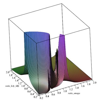
Fig. 6. Amplitude-frequency
characteristics of the dynamical
system – tilting angle
![]()
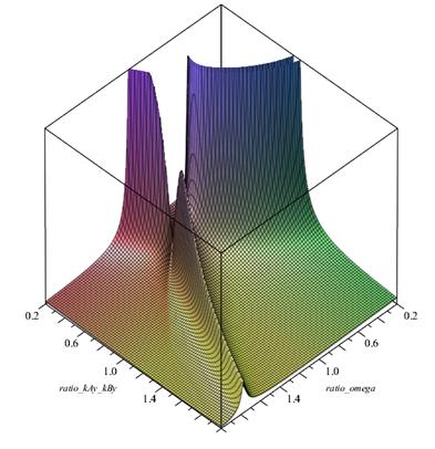
Fig. 7. Amplitude-frequency
characteristics of the dynamical
system – tilting angle
![]()
Stated conclusions can be
demonstrated in a concrete example of the pneumatic suspension of the base
block.
3. REALISING OF PROPOSED SUSPENSION
The proposed solution of tilting minimisation of the base block was realised in a specific case of life tests in the automotive industry. The base with dimensions of ![]() and mass
and mass ![]() was suspended
by pneumatic suspension according
to Figure 1. The mechanical
model of this dynamical
system belonged to the configuration
in Figure 5. Testing facility was serviced in the supra-resonance frequency area by a dominant exciting frequency
was suspended
by pneumatic suspension according
to Figure 1. The mechanical
model of this dynamical
system belonged to the configuration
in Figure 5. Testing facility was serviced in the supra-resonance frequency area by a dominant exciting frequency ![]() .
.
The pneumatic suspension of the base desk (Figure 8) was realised through the suspension and regulation of the pneumatic spring that enabled position change of the elasticity centre.
Suspension pneumatic springs were connected through air tubes in “differential adjustment” when the tilting stiffness is relatively low.
Pneumatic springs were connected to pressure vessels for reaching a higher volume value of the compressed air, decreasing the stiffness (Figure 9).
The minimisation principle of the base desk tilting was verified during the testing of car chassis by measuring the kinematic characteristics and evaluating them through operating deflection shapes [4].
Operating deflection shapes of the base block, which
prove the minimisation of tilting angle ![]() based on the appropriate shifting of the
elasticity centre
based on the appropriate shifting of the
elasticity centre ![]() ,
are shown in Figure 10.
,
are shown in Figure 10.
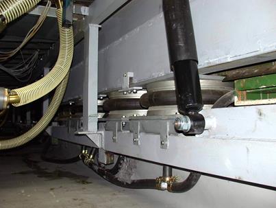
Fig. 8. Pneumatic vibroisolation
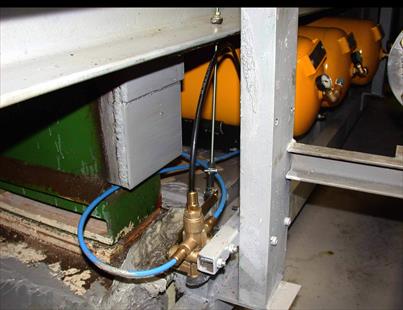
Fig. 9. Connection of pneumatic springs with pressure vessels
Operating deflection shapes show tilting ![]() is not entirely eliminated. This is
caused by exciting forces with a diverse and randomised character that appear during the life testing of car
chassis. Operating deflection shapes
are likewise influenced by the mass distribution
of objects placed on the base desk. When
the mass centre does not belong to the vertical plane of symmetry, undesirable parts of oscillation (tilting) occur (Figure 10).
is not entirely eliminated. This is
caused by exciting forces with a diverse and randomised character that appear during the life testing of car
chassis. Operating deflection shapes
are likewise influenced by the mass distribution
of objects placed on the base desk. When
the mass centre does not belong to the vertical plane of symmetry, undesirable parts of oscillation (tilting) occur (Figure 10).
The design of testing facilities and their placing to the base desk should respect even mass distribution. It means that the mass centre of the oscillating system should belong to the vertical plane of symmetry. A dominant part of the excitation force should similarly belong to the vertical plane of symmetry.
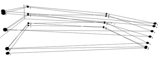
Fig. 10. Operating deflection shapes of the base block
In practice, by meeting the optimal state of mass distribution on the base desk and optimal position of excitation force, we need to note that certain tilting will still appear according to damping forces caused by used dampers. Usually, these damping forces are small with respect to the velocity amplitudes of oscillating motion at positions of dampers.
4. CONCLUSIONS
In dynamical testing shops, especially in the automotive industry, base blocks are used for assembling testing facilities. They are often used for life tests of mechanical parts, assemblies and cars. Dynamical forces acting on the base block are usually substantial, and due to the effort of effective use of space, dynamical forces do not act at the mass centre of suspended bodies. Then, dynamical moments occur, causing undesirable oscillating motion by tilting the block. This process may negatively affect the measured data during testing. Therefore, tilting minimisation of the base block by the simplest solution is demanded in service. One of the possibilities is the proposed pneumatic suspension of the base block with natural frequency regulation.
Acknowledgement
This work was supported by the Student
Grant Competition of the Technical University of
Liberec, under project No. SGS-2019-5036.
References
1.
Harris C.M. 2005. Shock and
Vibration Handbook. New York: McGraw-Hill.
ISBN: 0-07-137081-1.
2.
Homišin J., P. Kaššay. 2009. “Comparison of Tuning in
Shipping System Using pneumatic Tuners of Torsional Oscillations”. Machine Modeling and Simulation:
147-154. ISBN: 978-80-89276-18-9.
3.
Zeman V., Z. Hlaváč.
2010. Kmitání mechanických
soustav. [In Czech: Vibration of mechanical systems]. Plzeň:
University of West Bohemia in Pilsen.
ISBN: 978-80-7043-337-9.
4. Navrátil
M. 1981. Měření mechanického
kmitání. Úvod do teorie snímačů. [In Czech: Measurement
of mechanical vibration. Introduction to sensor theory]. Praha: SNTL.
Received 20.09.2021; accepted in
revised form 06.11.2021
![]()
Scientific Journal of Silesian University of Technology. Series
Transport is licensed under a Creative Commons Attribution 4.0
International License