Article
citation information:
Szczucka-Lasota, B., Węgrzyn, T., Łazarz,
B., Jurek, A., Wilczyński,
K.I. Welding of S355J+N low alloy
steel elements in railway carriages structures. Scientific Journal of Silesian University of Technology. Series
Transport. 2021, 112, 191-200. ISSN:
0209-3324. DOI: https://doi.org/10.20858/sjsutst.2021.112.7.15
Bożena
SZCZUCKA-LASOTA[1], Tomasz WĘGRZYN[2], Bogusław
ŁAZARZ[3],
Adam JUREK[4],
Krzysztof I. WILCZYŃSKI[5]
WELDING
OF S355J+N LOW ALLOY STEEL ELEMENTS IN RAILWAY
CARRIAGES STRUCTURES
Summary. Various types of
structures and materials play an important role in the creation modern means of
transport, including various grades of steel with different mechanical
properties. For the rolling stock, proper operation and meeting the operational
conditions is very important. Welded structures play an important role in the
construction of various means of transport. Correct welding of carriages is
important both in production and when carrying out various types of repairs.
Each repair a carriage depends on its advancement and condition and the time of
its operation. Each inspection for a refurbished carriage is defined either by
the service life or the big distance traveled by the
carriage. Important factor that may lead to damage is the effect of the load transported
in the carriage. Therefore, the causes of the wear of the rolling stock are
investigated and measures are taken to prevent any damage. The appropriate
technical condition of the carriage also ensures safety on railroads for users
and owners of the rolling stock. In the case of welded structures in carriages,
it is influenced by poorly materials choice, incorrectly selected production
processes and wrong selection of parameters. The goal of this paper is the
mechanical properties analyse of weld low alloy steel structure of carriages
after MAG welding using the parameters of the process. Thick-walled steel
structures are used to build carriages, which is often a serious welding
problem. The main role of welding conditions is connected with filer materials,
welding technology, state of stress and temperature. In this paper, the
properties of low alloy steel S3555J+N structures
after MAG welding are presented. Furthermore, metallographic structure, tensile
strength, bending test and impact toughness welded joints were analysed
regarding welding parameters. The amount of acicular ferrite in WMD oxygen after welding was tested. Gas mixtures of argon
and carbon dioxide with various percentage was used for shielding gas.
Keywords: transport, welding, carriages
1. INTRODUCTION
This
article deals with broadly
understood welding problems in transport. It was decided to focus on matters that concern all modes of
transport, and in this particular case, connections used in carriages and rail
transport means in general. There is an increasing need for high impact
toughness sheet steels for railway applications. Thus, a large part of current
sheet steel research is focused on the development of high strength steels
combining high tensile, good elongation, good impact toughness and innovative
welding technologies [1-4]. The choice of alloying elements is very important
due to their influence on the microstructure, tensile strength and impact
toughness [5, 6]. The largest contribution of the steel composition is related
to the effect of alloying elements on the microstructure, which determines most
of the mechanical properties of the final product. The influence of the
chemical composition of low steel WMD on Charpy V impact properties has been carefully analysed for the last 15 years [7, 8]. In S355J+N (EN10025-2:2004) steel
and the wire SG3 (EN ISO
14341-A: G 46 5 M G4Si1) intended for this steel,
there are mainly such elements such as C, Mn, Si, Cu,
Al, P, S. Mn is treated as the carbide former that is
simultaneously austenite stabilisers. Cu is a
non-carbide former that is simultaneously austenite stabilisers.
Si, P, Al are non-carbide formers that are ferrite stabiliser.
An important role in the tensile properties of WMD is
also played by oxygen. According to the current opinion, there is an optimum
percentage of oxygen that gives optimal metallographic structure and the
highest impact properties [9, 10]. The effect of oxygen on the good properties
is recognised the best in the MMA
welding process (Figure 1).
It was decided to focus on matters that concern all modes of transport, and in this particular case, connections used in carriages and rail transport in general.
Analysing Figure1, it is
easy to deduce that the less oxygen is in WMD, the
higher the impact toughness. It can be observed that the second class of impact
toughness of weld metal deposit (47 J at -20°C) corresponds with a content not greater than 350 ppm
oxygen in WMD. In other welding processes,
these values (optimal oxygen amount in WMD) may be
slightly different [11, 12].
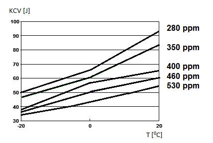
Fig. 1. The influence of oxygen on
impact toughness properties of the WMD [2]
2. MATERIALS AND METHODS
Steel S355J+N
is increasingly used in civil engineering and transport due to its good
strength and high elongation. The tensile strength of this steel is high, and
the relative elongation is very acceptable (Table 1). Therefore, it is
recommended to limit the linear energy during the welding process to the level
of 5 kJ/cm [2].
Table 1 presents the mechanical
properties of S355J+N steel used for welded elements
of carriages.
Tab. 1
Mechanical properties of S355J+N steel [8]
|
Steel |
The yield point YS, MPa |
Tensile strength UTS, MPa |
Relative elongation A5, % |
|
S355J+N |
600 |
400 |
15 |
Thick-walled structures used to
build carriages are considered difficult to weld due to appearing cracks in the
weld (less often than in the heat affected zone) [1]. Hence, it is extremely
important to correctly select the chemical composition of the wire and the
appropriate welding parameters. Table 2 presents the chemical composition of S355J+N steel.
Tab. 2
Chemical composition of S355J+N [8]
|
Steel grade |
C, % |
Si, % |
Mn, % |
P, % |
S, % |
Al, % |
Cu, % |
O, ppm |
|
S355J+N |
0.19 |
0.55 |
1.7 |
0.035 |
0.035 |
0.01 |
0.6 |
95 |
It is easy to notice a very high
content of phosphorus and sulfur. According to the
definition of steel quality, it should not be more than 0.03% P + S in total.
Excessive content of P and S creates welding difficulties. The following
electrode wires were selected: SG3 (EN ISO
14341-A: G 46 5 M G4Si1). The chemical composition of the welding wire is
presented in Table 3.
Tab. 3
Electrode wires used in the research
- chemical composition [12]
|
wire |
C % |
Si % |
Mn % |
P % |
S % |
|
SG3 |
0.08 |
0.85 |
1.7 |
0.021 |
0.021 |
The chemical composition of steel
and wire differs slightly. The diameter of the electrode wire was 1.2 mm. In
both cases, three different welding speeds were verified: 300, 350 and 400 mm/min.
According to the literature recommendations, the welding speed was changed
three times to assess which linear energy is the most appropriate [8, 9]. The
source of a direct current was connected to (+) on the electrode, the
thick-walled weld was triple-stitched.
In addition, a joint of the tested
sheets was made with a thickness of 12 mm, to analyse the strength and bending
resistance. Similarly, again, in this case, the diameter of the electrode wire
was 1.2 mm. Arc voltage 19 V and welding current 130 A were applied to the
first layer, arc voltage 25 V and welding current 200 A were chosen for the
second and third layer of the weld. Thus, the weld was triple-stitched. In
addition, in this part of the study, two various argon shielding mixtures: Ar + 18% CO2 and Ar
+10% CO2 (according to PN-EN 14175 norm)
were used.
3. METHODS AND SCOPE OF RESEARCH
The research included
non-destructive testing (NDT):
- visual testing (VT) of prepared welded joints was done
with the use of an eye armed with a magnifying glass at the magnification of
3× – test was done according to the PN-EN
ISO 17638 norm, assessment criteria according to the EN
ISO 5817;
- magnetic particle testing (MT) – tests were
carried out according to the PN-EN ISO 17638 norm,
with assessment performed according to the EN ISO
5817, using a magnetic flaw detector of REM-230 type;
- radiographic tests – tests were carried out according to the PN-EN ISO 15614-1 norm. The type of radiation source was
SMART 200.
Amongst the destructive tests, the
following assessments of the researched pin to platform arm weld were performed:
- examination of the macrostructure of specimens
digested with the use of Adler's reagent and a light microscope (LM);
- hardness measurement (HPO 250 hardness tester, HV10 test method).
In addition, for a mixed testing MAG
joint made of two 12 mm thick sheets, the following tests were carried out:
- tensile strength test using a machine (ZWICK 100N5A strength testing machine);
- bending test (ZWICK 100N5A strength testing machine).
4. RESULTS AND DISCUSSION
A butt-type welded joint (BW)
from S355J+N steel was made. MAG (135) welding method
was applied in the down position (PA) according to the EN
15614-1 norm. The material preparation for triple-stitched welding is presented
in Figure 2.
Fig. 2. Welding method and groove
shape
To assess the weldability of the mobile platform
components (pin and platform arm), two argon mixtures: 82% Ar-18%
CO2 and 90% Ar-10% CO2 were
selected to act as shielding gases, and wire SPG3 was
applied. After the welding, the following non-destructive tests (NDT) were
carried out: visual (VT), magnetic particle (MT) and radiographic. The results
of the created mobile platform joint are presented in Table 4.
The table data shows that the type of a shielding
mixture as well as the type of an electrode wire, and especially, the type of
the linear energy affects the quality of the produced joint. For all twelve
tested cases, no cracks in the MAG weld appeared in only two cases when:
-
90% Ar-10% CO2
was used as the shielding gas mixture,
- the welding speed was at the level of 300 or
350 mm/min,
- interpass
temperature was below 250°C.
These mentioned welds received the quality level B
according to the PN-EN ISO 5817 norm. The image
quality was W18 according to the EN
ISO 19232-1 norm. Non-destructive testing showed that the less oxidising argon
mixture (90% Ar-10% CO2) is
more appropriate as its use allows to avoid cracks in welds.
4.1. Results of destructive testing
For hardness testing, only joints made with the
welding speed of 300 mm/min were considered. Joint hardness distribution was
also carried out. The results are presented in Table 5.
Analysing the data from Table 5, it can be noted that
the hardness value in the whole joints was always below 220 HV.
Slightly lower hardness values occurred in joints with uncontrolled interpass temperature, which can be explained by the
possibility of ferrite grain growth.
Tab. 4
Assessment of non-destructive testing of the movable platform joint
|
Shielding gas |
Interpass temperature |
Welding speed 300 mm/min |
Welding speed 350 mm/min |
Welding speed 400 mm/min |
|
90% Ar-10% CO2 |
below 250°C |
No
cracks |
No
cracks |
Cracks in the weld |
|
82% Ar-18% CO2 |
below 250°C |
Cracks in the weld |
Cracks in the weld |
Cracks in the weld |
|
90% Ar-10% CO2 |
over 250°C |
Cracks in the weld |
Cracks in the weld |
Cracks in the weld and HAZ |
|
82% Ar-18% CO2 |
over 250°C |
Cracks in the weld |
Cracks in the weld |
Cracks in the weld and HAZ |
Tab. 5
Hardness distribution in the joints
|
Shielding gas |
Interpass temperature |
Base material |
HAZ |
Weld |
HAZ |
Base material |
|
90% Ar-10% CO2 |
below 250°C |
167 |
214 |
205 |
213 |
165 |
|
82% Ar-18% CO2 |
below 250°C |
155 |
207 |
202 |
212 |
161 |
|
90% Ar-10% CO2 |
over 250°C |
168 |
216 |
207 |
215 |
166 |
|
82% Ar-18% CO2 |
over 250°C |
159 |
209 |
201 |
211 |
164 |
4.2. Strength tests
To obtain additional information regarding the
correctness of the joint, it was decided to perform tensile strength tests.
Once the joints welded with various parameters were completed, tests of
immediate tensile strength were performed. Joint strength tests were carried
out on the ZWICK 100N5A strength testing machine.
Dimension of cross section of the sample was 12 mm × 25 mm. The results
of the mechanical tests of the welds (an average of three measurements) are
presented in Table 6. Only joints with a controlled interpass
temperature below 250°C were
taken for testing (because only these have no cracks).
The analysis of the array data shows that the welds
were made correctly because the nominal value of this joint should be in the
range of 470 MPA to 630 MPa.
Next, the bending test of the created joints was
performed. For the test, a sample with a thickness of a = 12 mm, width of b =
25 mm, mandrel of d = 40 mm were used, the required bending angle was at the
level of 180°. Five bending measurements were carried out both on the face
side and on the root side of the weld. The tests results are summarised in
Table 7.
Tab. 6
Mechanical properties of the joints
|
Shielding gas |
Interpass temperature |
Rm, MPa |
A5, % |
|
90% Ar-10% CO2 |
below 250°C |
551 |
14.3 |
|
82% Ar-18% CO2 |
below 250°C |
557 |
13.9 |
Tab. 7
Joint bending test results
|
Shielding gas |
Interpass temperature |
Side deformation |
Size [mm] |
Comments |
|
90% Ar-10% CO2 |
below 250°C |
Root of the weld |
12 x 25 |
No cracks, no incompatibilities |
|
90% Ar-10% CO2 |
below 250°C |
Face of the weld |
12 x 25 |
No cracks, no incompatibilities |
|
82% Ar-18% CO2 |
below 250°C |
Root of the weld |
12 x 25 |
No cracks, no incompatibilities |
|
82% Ar-18% CO2 |
below 250°C |
Face of the weld |
12 x 25 |
No cracks, no incompatibilities |
The analysis of Table 7 shows that the joints were
made correctly. No cracks or other incompatibilities were found in the tested
samples.
4.3. Metallographic examination
Next, the microstructure analysis was performed.
Amount of acicular ferrite was counted in all tested cases (Table 8).
Tab. 8
Acicular ferrite and MAC phases in WMD after MAG welding
using wire A regarding various micro-jet parameters
|
Shielding gas |
Interpass temperature |
Acicular ferrite [%] |
|
90% Ar-10% CO2 |
below 250°C |
45 |
|
82% Ar-18% CO2 |
below 250°C |
42 |
|
90% Ar-10% CO2 |
below 250°C |
37 |
|
82% Ar-18% CO2 |
below 250°C |
35 |
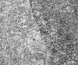
It is easy to observe that
acicular ferrite with a percentage above 40% was obtainable only after MAG
welding with controlled interpass temperature below 250°C. Typical structure of the weld is presented in
Figure 3.
Fig. 3.
Acicular ferrite (45%) in MAG weld
(shielding gas mixture 90% Ar-10% CO2,
controlled interpass temperature below 250°C)
In the last part of the research, WMD impact toughness was tested at -20 and -40°C. Only joints with a controlled interpass
temperature below 250°C were taken for testing (because only these
have no cracks) – Tables 9.
Tab. 9
Impact toughness for
MAG welding
|
Shielding gas |
Interpass temperature |
Impact toughness [J] at -20°C |
Impact toughness [J] at -40°C |
|
90% Ar-10% CO2 |
below 250°C |
82 |
51 |
|
82% Ar-18% CO2 |
below 250°C |
76 |
44 |
Analysing the table data, it can be observed that the impact toughness of the junction is more favourable when the shielding gas 90% Ar-10% CO2 is used. Only in this case, the fourth class of impact toughness is fulfilled with the breaking energy above 45 J at -40°C. This is due to the less oxidising nature of this sheath mixture as compared to the 82% Ar-18% CO2 mixture.
3. CONCLUSIONS
Joints were made of S355J + N steel, used in the construction of carriage components. Welding a thicker structure of this steel is not easy due to the (elevated) content of phosphorus and sulfur, which is twice as high as the accepted requirements for the quality of low alloy steel. Developing the welding method, it was decided to focus on the correct selection of the gas mixture and the thermodynamic conditions of the joint. Two argon mixtures with different carbon dioxide additions (90% Ar-10% CO2 and 82% Ar-18% CO2) were tested. It was decided that preheating before welding was not needed, but it was important to control the interpass temperature not to exceed 250°C. NDT tests showed that the joint has no welding defects and incompatibilities only when the interpass temperature is below 250°C. Thereafter, destructive tests were performed to check the correctness and quality of the joint. Joint hardness and tensile strength tests and bending tests were carried out. In all tested cases, it was confirmed that the joint is correctly done according to the nominal requirements for this type of design. The final stage of the research was to check the impact toughness of the joint, which showed that both mixtures used for welding are correct and allow to obtain a nominal value corresponding with the second impact class. To obtain the fourth impact strength class, a gas mixture should be used as a shielding gas, less oxidising the weld 90% Ar-10% CO2.
References
1.
Hadryś Damian. 2016. “Mechanical properties of plug welds after micro-jet cooling”.
Arch. Metall. Mater 61: 1771-1775.
2.
Hadryś Damian. 2015. “Impact load of welds
after micro-jet cooling”. Archives
of Metallurgy and Materials, 60 (4): 2525-2528.
3.
Samardžić I., M. Dunđer, M. Katinić, N. Krnić. 2017. “Weldability investigation on real
welded plates of fine-grained high-strength steel S960QL”.
Metalurgija
56(1-2):
207-210. ISSN: 0543-5846.
4.
Spišák
E., J. Majerníková, J. Slota. 2014. “Change of ears creation of AHSS steels after heat treatment of zinc coating”. Metalurgija
53(4): 473-476. ISSN: 0543-5846.
5.
Stanik Zbigniew. 2014.
“Mechatronic Systems, Mechanics and Materials”. Solid State Phenomena 210: 58-64.
6.
Evans Godfrey Matthew. 1994. ”Microstructure
and properties of ferritic steel welds containing Al and Ti”.
Oerlikon-Schweissmitt
130: 21–39.
7.
Fornalczyk A., J. Willner, J. Cebulski, D. Pasek, M. Saternus, P. Czech. 2016. “Structure and surface
state of different catalytic conveters applied in
cars”. The 5th international Lower Silesia-Saxony conference
“Advanced Metal Forming processes in automotive industry (AutoMetForm 2016)”: 327-333.
8.
Fornalczyk A., M. Saternus, J. Willner,
M. Fafiński, H. Kania, P. Czech. 2016. “The results of
platinum recovery from metal substrate catalytic converters by using
magneto-hydro-dynamic pump”. 25th Anniversary International Conference
on Metallurgy and Materials “METAL 2016”: 1382-1387. ISBN:
978-80-87294-67-3.
9.
Burdzik Rafał, Łukasz Konieczny, Zbigniew
Stanik, Piotr Folęga, Albert Smalcerz,
Aleksander Lisiecki. 2014. „Analysis
of impact of chosen parameters on the wear of camshaft”. Archives of Metallurgy and Materials 59 (3): 957-963.
10. Kasuya T., Y. Hashiba,
S. Ohkita, M. Fuji. 2001. “Hydrogen distribution in multipass submerged arc weld metals”. Science and Technology of Welding &
Joining 6(4):
261-266. DOI: 10.1179/136217101101538767.
11. Lukaszkowicz
Krzysztof, Leszek Dobrzański, et al. 2012. „Characterization and properties of PVD coatings applied to extrusion dies”. Vacuum 86: 2082-2088.
12. Evans Godfrey Matthew. 1992.
“The effect of micro-alloying
elements on the microstructure and properties of ferritic all-weld metal deposits”.
IIW Doc II-A-855-92: 1-20.
Received 27.03.2021; accepted in revised form 12.06.2021
![]()
Scientific
Journal of Silesian University of Technology. Series Transport is licensed
under a Creative Commons Attribution 4.0 International License