Article
citation information:
Puškár, M., Kopas, M., Šoltésová,
M., Lavčák, M. System for analysis and correction
of motor management. Scientific Journal
of Silesian University of Technology. Series Transport. 2021, 111, 129-136. ISSN: 0209-3324. DOI: https://doi.org/10.20858/sjsutst.2021.111.11.
Michal PUŠKÁR[1],
Melichar KOPAS[2],
Marieta ŠOLTÉSOVÁ[3], Matúš LAVČÁK[4]
SYSTEM
FOR ANALYSIS AND CORRECTION OF
MOTOR MANAGEMENT
Summary. The innovative system, which was developed for analysis and correction of motor
management, is determined
for the solution of practical
problems concerning the operation of the piston combustion
engines. Programming of the ignition
curves and fuel maps without relevant
feedback, namely, without information obtained from the engine operation, increases the risk of detonation combustion, which can destroy
the combustion engine. However, the main application area of this system is the development of
an algorithm, which is specified
for control of the combustion
process based on the HCCI technology (Homogenous Charge Compression Ignition). Nowadays, the functional principle of the HCCI engine is one of the most effective possibilities on how to reach higher
operational efficiency of
the gasoline engine, that is, closer
to the efficiency level of
the diesel driving units.
Keywords: system, analysis, correction, motor management
1. INTRODUCTION
Presently,
many production companies around the world offer a wide range of electronics,
including programmable electronic control units determined for installation in
various models of piston combustion engines [1-3]. The programmable electronic
control units enable to perform very detailed simulation of the engine ignition
curve using either the 2-dimensional or the 3-dimensional simulation method.
Application of the 2-dimensional method means that the actual value of the
ignition advance angle is a function of the engine operational speed. The
second possibility, that is, application of the 3-dimensional method, means
that the angle of advanced ignition is not only a function of the engine speed,
but also depends on the actual position of the throttle installed in the input
pipe [4]. The throttle position determines the real amount of the fuel-air
mixture that is delivered into the combustion engine.
However,
a relevant problem occurs in the real operation of the combustion engine. This
problem is that the values programmed during the simulation process (that is,
the values of advanced ignition at various engine speed levels), do not usually
correspond with reality. The individual impulses obtained from the measuring
sensor changes with the given type of combustion engine. For example,
variability of the impulse shape, which is typical for the input impulses as
well as their delay, especially at higher engine speed levels (above 10,000
rpm); cause significant deformation of the output data correctness [5-7].
Based
on this, an innovative system, which enables tuning the universal control unit
to the concrete type of the engine-working regime, was developed by our
research team. Further, this system defines the correction curve for the input
values during the programming of the ignition curves and fuel maps.
2. ANALYSIS OF IGNITION IMPULSE
First, it is
necessary to note the measuring of impulse produced by the impulse generator.
This generator is connected with the engine crankshaft. The measuring process
is based on the application of an oscilloscope. The main task of the measuring
procedure is the collection of real data, which describe the analysed
parameter. In the case that the values obtained from the measuring procedure
are utilised within the engine control process, hence, it is necessary to
ensure that the installed measuring apparatus fulfils the required metrological
characteristics.
Fig. 1. Generator
of impulses for combustion engine
Of course, this
requirement is equally valid for the application of the above-mentioned
oscilloscope. It is necessary to emphasise an important fact that every
deviation, which occurs during the measuring activity, has a negative impact on
the measuring process and it causes an incorrect function of the engine control
unit. There are two main constructional parts of the impulse generator: the
sensor of impulses and the rotor, which is directly connected with the
crankshaft (Figure 1).
The value of basic
advance is given by the setting of the generator. It corresponds to the
"base advance" angle. Figure 1 illustrates the top dead centre
position [6]. It is recommended to verify whether a real advance in the given
engine is following the advance, which was determined using a stroboscopic
lamp.
The sensor of
impulses is a very important part of the electronic ignition system. It is
necessary to apply such kind of sensor, which can satisfy the ascending edge
condition (that is, the change of voltage) within the interval from 0 to 1.5 V.
This requirement fulfils the inductive sensor of rotation [8-11].
An ignition spark
is generated by the system of ignition and the spark-coil according to the
impulses from the rotational sensor.

Fig. 2.
Signal obtained from impulse sensor (part above) and in CDI (part below)
Figure 2
illustrates a shape of the impulse coming from the sensor of impulses in such
form, which is presented from the oscilloscope. A specific position of the
rotor, namely, the position opposite the sensor, is situated at 32º before reaching the top dead centre. This situation
illustrates the left circle in Figure 2, whereby generation of the impulse
starts just in this moment. Amplitude of the impulse is increasing in the
negative direction regarding the central axis. After one half of amplitude
begins a rapid reversing in such a moment, when the rotor is not in
interference. The impulse amplitude further continues in the previous direction
to reach the maximum negative value, and consequently, it is returning back to
the central line. The impulse amplitude passes through the central line at
approx. 7º before the level of the top
dead centre. The above-described deviation creates a specific interval, which
is called “the trigger interval”, whereby this oscillation lasts
during approx. 25º within rotation of the
engine crankshaft. Finally, the positive amplitude occurs after crossing the
projection lug in the rotor. The lug is visible in Figure
The signal
obtained from the sensor is the input signal to the control unit to be
processed [12, 13]. The bottom part of Figure 2 illustrates the signals
modified in the universal programmable control unit CDI. Further presented in
the given figure is a mutual comparison of the processed signals and the
scanned signals. It is visible from the same figure that the final version of
the signal, which is processed in the control unit CDI, has the values situated
only in the positive part of the axis, namely, with three main amplitudes. It
is also evident that this signal is periodically repeating after each
revolution of the rotor, that is, after every 360º.
3. PRINCIPLE OF THE MEASURING METHOD
The described system, which is
determined for analysis and correction of motor
management (Figure 3), consists of the electric motor, sensor of
impulses, stroboscopic lamp, speed indicator and speed regulator. The rotor of
the electric motor is connected with the disc protractor. The disc protractor
generates an electric signal through a lug shaped in the form of a sector of a
circle.
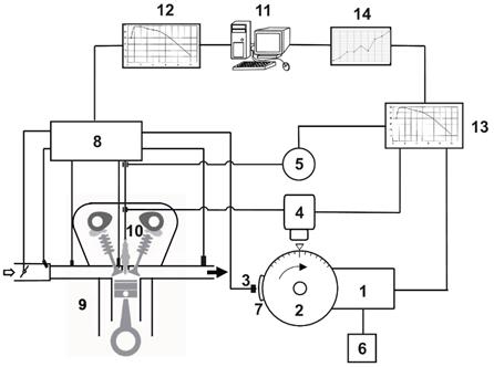
Fig. 3.
System for analysis and correction of motor
management
(1, 2 –
high-speed electric motor with disc protractor; 3 – impulse sensor; 4 –
generator of stroboscopic effect; 5, 6 – speed indicator with speed regulator; 7
– sector of circle, which generates impulses; 8 – control unit; 9
– combustion engine; 10 – spark plug; 11 – PC;
12 – input curve; 13 – real curve; 14 – correction curve)
The generated electric signal is
detected by the impulse sensor, which is jointed to the engine control unit.
The stroboscopic lamp is emitting a light ray oriented to the disc protractor
just at the moment of simulated ignition of the fuel-air mixture. The speed
indicator and the stroboscopic lamp are connected to the cable of the engine
spark plug. The speed regulator enables utilising the whole spectrum of the
engine speed. The time behaviour of the real ignition curve is recorded on the
disc protractor using the stroboscopic method. Consequently, there is utilised
the principle of comparison between the real ignition curve and the input
ignition curve, which is installed into the engine control unit by a personal
computer (PC). The result of this procedure is the correction curve, which
serves for modification of the input data.
The main advantage of this solution
is that it enables obtaining the correction curve relatively fast with a
satisfactory accuracy. The question of deviations concerning the real output
values of the ignition curve as well as the importance of the fuel map are
especially relevant in the high-speed engine operational area and they have a
significant influence on the operational stability of the HCCI
combustion process.
4. APPLICATION OF THE PRESENTED SYSTEM
The presented measuring method was
practically verified in the case of the experimental combustion engine. There
was applied the control unit (CDI) during the whole measuring process.
Regulation of the advanced ignition is based, in this case, on two adjustable
ignition curves within the interval from 0 to 90° at the engine speed level
from 100 to 15,000 rpm. It is possible to set all the functions and various
operational ignition regimes using a PC equipped with a special software
application called the Ignition Control. This application also enables to
obtain online visualisation of the most important engine operation values, that
is, the values of advanced ignition, engine speed as well as the inputs in
digital and analogue forms. The ignition system is connected to the PC using an
interface - USB cable [14-16].
There was programmed and implemented
into the control unit, the input ignition curve through the PC. This ignition
curve is a part of the control algorithm, which is utilised for control of the
combustion process. After the start, the speed of the electric motor with the
disc protractor was set on the required initial value using the speed regulator.
The stroboscopic lamp is emitting a light ray to the disc protractor at the
moment of simulated ignition of the fuel-air mixture. The result is a light
effect of a seeming stopping of the disc protractor in the simulated ignition
position. The disc protractor indicates the advanced ignition value, and at the
same time, the speed indicator offers the corresponding engine speed value. It
is obtained, in this way, one operational point of the real ignition curve. The
speed regulator allows performing of a sequential change of the engine speed
within the above-mentioned speed interval, and thus, it is possible to
investigate the whole behaviour of the real ignition curve. The real ignition
curve was compared with the programmed ignition curve using the PC and this
process of comparison resulted in the correlation curve. The correlation curve
serves for the input data modification.
5. CONCLUSIONS
The
innovative measuring process described in this article enables to perform very
precisely, a tuning procedure concerning the ignition control unit for each
kind of combustion engine. This measuring methodology represents a significant
contribution to the operational safety of the combustion engine. Namely, it
reduces the risk of detonation combustion due to the elimination of
incorrect outputs. In this way, it also significantly increased the global
operational reliability of the combustion engine, especially during the
application of the HCCI technology. This technology
utilises the principle of self-ignition of the homogenous fuel mixture using
the compression stroke. The homogenous fuel mixture is combusted in the whole
combustion volume at the same time, that is, there is combusted almost the
whole fuel mixture. Therefore, exploitation of the fuel is very effective,
however, there are some serious problems concerning the application of the HCCI technology. The most relevant of them are high
compression pressures, excessive heat release and demanding control of the
self-ignition process. Development of an algorithm, which is determined for the
operational control of the combustion process, is one of the main conditions
that are necessary for the practical and reliable application of the HCCI technology. The system described in this article
represents a significant contribution for better feedback regarding the control
components of motor management.
Acknowledgements
This work was supported
by the Slovak Research and Development Agency under Contract No. APVV-19-0328.
This article was written
in the framework of the Grant Projects: VEGA 1/0318/21 “Research and
development of innovations for more efficient utilization of renewable energy
sources and for reduction of the carbon footprint of vehicles” and KEGA 006TUKE-4/2020
“Implementation of Knowledge from Research Focused on Reduction of Motor
Vehicle Emissions into the Educational Process.”
References
1.
Puskar Michal,
Peter Bigos, Michal Kelemen,
Roman Tornhajzer, Martin Sima.
2014. „Measuring method for feedback provision during development of fuel
map in hexadecimal format for high-speed racing engines”. Measurement 50: 203-212. DOI: 10.1016/J.MEASUREMENT.2014.01.005.
2.
Brestovic Tomas, Natalia Jasminska, Maria Carnogurská,
Michal Puskar, Michal Kelemen, Milan Filo. 2014.
„Measuring of thermal characteristics for Peltier thermopile using
calorimetric method”. Measurement 53: 40-48. DOI: https://doi.org/10.1016/j.measurement.2014.03.021.
3.
Wierzbicki Sławomir. 2019. “Evaluation of the effectiveness
of on-board diagnostic systems in controlling exhaust gas emissions from motor
vehicles”. Diagnostyka 20(4): 75-79.
4.
Czech Piotr. 2013. „Intelligent
Approach to Valve Clearance Diagnostic in Cars”. Communications
in Computer and Information Science 395: 384-391.
DOI: https://doi.org/10.1007/978-3-642-41647-7_47.
Springer, Berlin, Heidelberg. ISBN: 978-3-642-41646-0; 978-3-642-41647-7. ISSN:
1865-0929. In: Mikulski Jerzy (eds), Activities of transport telematics,
13th International Conference on Transport Systems Telematics, Katowice Ustron,
Poland, October 23-26, 2013.
5.
Puskar Michal,
Tomas Brestovic, Natalia Jasminska.
2015. „Numerical simulation and experimental analysis of acoustic wave
influences on brake mean effective pressure in thrust-ejector inlet pipe of
combustion engine”. International
Journal of Vehicle Design 67(1): 63-76. DOI:
https://doi.org/ 10.1504/ijvd.2015.066479.
6.
Czech Piotr. 2011. „Diagnosing
of disturbances in the ignition
system by vibroacoustic signals
and radial basis function - preliminary research”. Communications
in Computer and Information Science 239: 110-117.
DOI: https://doi.org/10.1007/978-3-642-24660-9_13.
Springer, Berlin, Heidelberg. ISBN: 978-3-642-24659-3. ISSN: 1865-0929. In:
Mikulski Jerzy (eds), Modern transport telematics, 11th International Conference on Transport Systems Telematics, Katowice Ustron,
Poland, October 19-22, 2011.
7.
Czech Piotr. 2013. „Diagnosing
a car engine fuel injectors' damage”. Communications in Computer
and Information Science 395: 243-250. DOI: https://doi.org/10.1007/978-3-642-41647-7_30. Springer, Berlin,
Heidelberg. ISBN: 978-3-642-41646-0; 978-3-642-41647-7. ISSN: 1865-0929. In:
Mikulski Jerzy (eds), Activities of transport telematics, 13th International Conference on Transport Systems Telematics, Katowice Ustron,
Poland, October 23-26, 2013.
8.
Dodok Tomas, Nadezda
Cubonova, Miroslav Cisar,
Ivan Kuric, Ivan Zajacko.
2017. „Utilization of strategies to generate and optimize machining
sequences in CAD/CAM“. 12th
International scientific conference of young scientist on suitable, modern and
safe transport 192: 113-118. May 31-June 02, 2017. High Tatras,
Slovakia. DOI: 10.1016/j.proeng.2017.06.020.
9.
Kuric Ivan, Miroslav Cisar, Vladimir Tlach, et al.
2018. „Technical Diagnostics at the Department of Automation and
Production Systems“. 2nd
International Conference on Intelligent Systems in Production Engineering and
Maintenance (ISPEM) 835: 474-484. Sep 17-18,
2018. Wroclaw, Poland.
10.
Puskar Michal,
Andrej Jahnatek, Ivan Kuric,
et al. 2019. „Complex analysis focused on influence of biodiesel and its
mixture on regulated and unregulated emissions of motor vehicles with the aim
to protect air quality and environment”. Air Quality Atmosphere And Health 12(7):
855- 864.
11.
Brezinova Janette., Anna Guzanova. 2012. „Possibilities of utilization high
velocity oxygen fuel (HVOF) coatings in conditions of
thermal cycling loading“. Metalurgija 51(2): 211-215.
12.
Zivcak Jozef,
Martin Sarik, Radovan Hudak.
2016. „FEA simulation of thermal processes
during the direct metal laser sintering of Ti64
titanium powder“. Measurement 94:
893-901. DOI: 10.1016/j.measurement.2016.07.072.
13.
Toth Teodor,
Radovan Hudak, Jozef Zivcak. 2015. „Dimensional verification and quality
control of implants produced by additive manufacturing“.Quality innovation prosperity - Kvalita inovacia prosperita 19(1):
9-21. DOI: 10.12776/QIP.V19I1.393.
14.
Homisin Jaroslav, Peter Kassay, Michal Puskar, Robert Grega,
Jozef Krajnak, Matej Urbansky, Marek Moravic. 2016. „Continuous tuning of ship propulsion
system, by means of pneumatic tuner of torsional oscillation. Transactions of the Royal Institution of
Naval Architects Part A: International Journal of Maritime Engineering 378.
DOI: 10.3940/RINA.IJME.2016.A3.378.
15.
Puskar Michal,
Andrej Jahnatek, Jaroslava Kadarova, et al. 2019. „Environmental study focused
on the suitability of vehicle certifications using the new European driving
cycle (NEDC) with regard to the affair “dieselgate” and the risks of NOx emissions
in urban destinations“. Air Qual Atmos Health 12: 251-257.
DOI: https://doi.org/10.1007/s11869-018-0646-5.
16.
Puskar Michal,
Michal Fabian, Jaroslava Kadarova,
Peter Blistan, Melichar Kopas. 2017. „Autonomous vehicle with internal combustion
drive based on the homogeneous charge compression ignition technology“. International Journal of Advanced Robotic
Systems 14(5): 1-8. DOI: 10.1177/1729881417736896.
Received 19.02.2021; accepted in revised form 02.05.2021
![]()
Scientific
Journal of Silesian University of Technology. Series Transport is licensed
under a Creative Commons Attribution 4.0 International License