Article
citation information:
Sabziev, E. A control algorithm for
joint flight of a group of drones. Scientific
Journal of Silesian University of Technology. Series Transport. 2021, 110, 157-167. ISSN: 0209-3324. DOI: https://doi.org/10.20858/sjsutst.2021.110.13.
Elkhan SABZIEV[1]
A
CONTROL ALGORITHM FOR JOINT FLIGHT OF
A GROUP OF DRONES
Summary. Using drones in groups
in the military field is not a novel idea. A massive attack by a large
amount of equipment is known to be very difficult to prevent. Therefore, it is
a good tactic to sacrifice some of the relatively cheap drones to destroy
special enemy targets in a massive attack. This raises the issue of joint
control of the behaviour of a group of drones. This paper proposes a System of
Systems ideology-based decision-making system that allows to individually
control each drone in a group flight. An algorithm is developed that allows
controlling drones by controlling their speed.
Keywords: group flight, drone, algorithm, system of
systems
1.
INTRODUCTION
The idea of using drones in groups in the military field involves
interlinked drones working together to increase the success probability of a
military operation. Speaking of "interlinked" drones, it is assumed
that when performing a task, each drone acts as a separate technical device
making an independent decision based on information obtained as a result of
data exchange with other members (drones) of its group. In addition, it is
assumed that all drones can participate in the data exchange. In this regard,
there is a need for group control of those drones.
Performing any task by drones
requires, first, their group flight to the operation site, which creates the
problem of organising a joint flight of a group of drones. The essence of this
problem is that each drone in a group flight should not be controlled by an
operator individually, but rather all drones in a group should work
effectively, guided by the instructions received from the operator at the
beginning of the flight. The paper by Baxter et al. [1] published in 2007 can
be considered as one of the first published works in the field of joint flight
control of a group of drones. The paper discusses the issue of organising joint
control of 4 unmanned aerial vehicles by an operator from one computer.
Essentially, in this instance, the operator creates a radio link with each
drone and controls it directly. Naturally, a control system organised in this
manner does not allow increasing the number of drones.
Scientific and technical
literature uses such concepts as multi-agent systems [2, 3] and System of
Systems [4] to describe and control group behaviour of objects of the same
type. Both concepts refer to the form of organising joint operation of several
systems to accomplish one task. The main difference between these concepts is
that while the elements of multi-agent systems are programs, the elements of a
System of Systems are objects of various nature. In a particular case when the
elements of System of Systems are programs, it becomes a multi-agent system.
Recently published studies that regard drones as elements of a multi-agent
system include [5-6]. An extensive review of research on the organisation of
joint flight of drones using multi-agent ideology is given in [7].
This study is guided by the
System of Systems ideology. The principles of a single decision-making system
for drones performing joint flight are developed, and an algorithm for
controlling the speed of the drone based on the information received from its
neighbours flying nearby is given.
2. THE
ESSENCE OF THE PROBLEM OF CONTROL IN JOINT FLIGHT
The use of a centralised control system during the
flight of drones to a remote military operation zone imposes strict conditions
on the radio communication and data exchange system: it requires, on the one
hand, transferring large amounts of data to cover all drones, and on the other
hand, increased power of radio communications as well as a larger battery capacity
to power the drones’ systems.
As a rule, the flight route of a group of drones is
set by the operator as a broken line against the background of the map. The
movement of each drone in the group involves its flight along a trajectory so
that this trajectory is as close as possible to the route line, enabling the
drones to reach the end of the route without colliding with each other.
With this in mind, we proposed creating joint
control of drone flight based on the System of Systems ideology. This means that
to achieve a common goal, each drone in a group flight needs to have an
independent decision-making system based on information about other drones in
its immediate vicinity. For simplicity, this paper does not consider the
topography of the flight zone and stationary obstacles.
During a real flight, drones exchange data at
discrete instants in time. After each data exchange, the data would be
processed and a decision is made on how to change the control parameters of the
drone. The decision-making algorithm should be universal and not cause internal
conflict when applied to different drones in flight.
Furthermore, it should be noted that numerous works
have been devoted to the study of the hardware and software aspects of data
exchange, hence, we consider this issue to be resolved.
3. KEY
HYPOTHESES AND PRINCIPLES
As
mentioned earlier, the decision-making algorithm should be universal, the
results should be unambiguous regardless of the amount of input data, and the
results of processing performed on different drones should not contradict each
other. To this end, the following assumptions and principles have been
formulated.
·
All drones have the same flight characteristics
– their maximum speed, cruise speed, permissible acceleration
(acceleration capacity) are assumed to be identical.
·
The system clocks of all drones are synchronised
and the time difference between different drones due to technical issues is
negligible.
·
Data received (transmitted) by drones have a single
structure: "drone number", "moment of data transmission
(reception)", "flight speed", "current coordinates ".
In the process of data exchange, each drone receives a full set of information
about nearby drones in a single format.
·
Drone’s flight direction is a set of primary
and randomly oriented "auxiliary" directions along a set trajectory.
The auxiliary direction is formed by differences in the thrust forces of the
engines, delays in the decision-making system, as well as in the transmission
of commands to the drone’s actuating units, the impact of wind and other
similar random factors. The drone’s movement is controlled by changing
the value and direction of its current velocity.
4. NOTATION
For clarity, a formal number is assigned to each
drone participating in a group flight. Suppose that there is ![]() drones involved
in a group flight, and they are numbered as
drones involved
in a group flight, and they are numbered as ![]() . Their movement will be calculated starting from the given
moment
. Their movement will be calculated starting from the given
moment ![]() . We denote the coordinates of the
. We denote the coordinates of the ![]() -th drone at the starting moment
-th drone at the starting moment ![]() by
by ![]() .
.
Suppose
that the nodal points of the planned route of the group are given by the
operator in the form of the sequence ![]() . Here,
. Here, ![]() is the first
nodal point on the route,
is the first
nodal point on the route, ![]() is the
number of the last nodal point. The trajectory of the group’s movement is
set by the broken line
is the
number of the last nodal point. The trajectory of the group’s movement is
set by the broken line ![]() passing through
passing through ![]() nodal points
nodal points ![]() , here
, here ![]() is the
"central" point of the group of drones at the starting moment
is the
"central" point of the group of drones at the starting moment ![]() , its coordinates can be calculated as the arithmetic mean of
the numbers
, its coordinates can be calculated as the arithmetic mean of
the numbers ![]() .
.
Let
us denote the ![]() -th drone's maximum speed by
-th drone's maximum speed by ![]() and its cruise
speed (cruise speed is the optimal speed of an aircraft or ship with low fuel
consumption) by
and its cruise
speed (cruise speed is the optimal speed of an aircraft or ship with low fuel
consumption) by ![]() . Its coordinates at the instant of time
. Its coordinates at the instant of time ![]() and the
components of the velocity vector will be denoted by
and the
components of the velocity vector will be denoted by ![]() and
and ![]() , respectively. Further, we will also use vector notation of
velocity
, respectively. Further, we will also use vector notation of
velocity ![]() . Following the main hypotheses and assumptions about the
technical capabilities of drones, there is such
. Following the main hypotheses and assumptions about the
technical capabilities of drones, there is such ![]() that satisfies
the constraint
that satisfies
the constraint ![]() .
.
It
is assumed that the drone regularly receives complete information about the
surrounding drones once each discrete instant in time ![]() during the group
flight. These are the drones around the
during the group
flight. These are the drones around the ![]() -th drone that are less than the set distance
-th drone that are less than the set distance ![]() apart.
apart.
5. SAFE
JOINT FLIGHT CONDITIONS
Thus,
it is assumed that the ![]() -th drone must fly along the line
-th drone must fly along the line ![]() , starting from the point
, starting from the point ![]() , trying to get as close to this line as possible. The
following conditions will need to be fulfilled to ensure the drones do not
collide.
, trying to get as close to this line as possible. The
following conditions will need to be fulfilled to ensure the drones do not
collide.
·
Regular data exchange between drones occurs at
discrete instants in time ![]() ,
, ![]() .
.
·
Since the size of the drone is very small relative to
its flight boundaries, it can be described as a material point. At each instant
of movement ![]() , the location of the
, the location of the ![]() -th drone in space is determined with a certain accuracy by
navigation devices as a material point.
-th drone in space is determined with a certain accuracy by
navigation devices as a material point.
·
Each drone has an individual safety zone around it.
This zone is a 3D sphere at the location point of the centre drone. In Fig. 1,
the individual zone of the ![]() -th drone located at the instant
-th drone located at the instant ![]() at the point
at the point ![]() , is shown as a sphere with a radius of
, is shown as a sphere with a radius of ![]() .
.
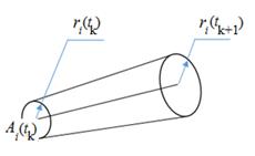
Fig. 1. Individual zone of the ![]() -th drone that it creates for other drones as the zone of
risk
-th drone that it creates for other drones as the zone of
risk
·
As the drone flies along the route, its individual
zone expands and forms a three-dimensional figure. This figure is a risk zone
for other drones. Depending on the current location and speed of the ![]() -th drone at the instant
-th drone at the instant ![]() , the boundaries of the risk zone it creates for other drones
can be estimated. This zone is the geometric locus of the spheres of the
individual zone moving in the direction of the vector
, the boundaries of the risk zone it creates for other drones
can be estimated. This zone is the geometric locus of the spheres of the
individual zone moving in the direction of the vector ![]() , starting from the point
, starting from the point ![]() , and with a radius that increases proportionally to the
distance travelled.
, and with a radius that increases proportionally to the
distance travelled.
·
Fig. 1 shows the risk zone created for other drones by
the movement of the ![]() -th drone in the period
-th drone in the period ![]() . The drone must fly in such a way as to progress
"along" the broken line
. The drone must fly in such a way as to progress
"along" the broken line ![]() , without entering the risk zone.
, without entering the risk zone.
·
The velocity vector of the ![]() -th drone consists of two components:
-th drone consists of two components: ![]() , where
, where ![]() is the velocity
vector parallel to the vector
is the velocity
vector parallel to the vector ![]() , and
, and ![]() is a vector
perpendicular to
is a vector
perpendicular to ![]() . For
. For ![]() and
and ![]() , the conditions
, the conditions ![]() ,
, ![]() are satisfied,
where
are satisfied,
where ![]() and
and ![]() are predetermined
numbers,
are predetermined
numbers, ![]() .
.
·
Flying along the segment ![]() , the drone must, upon reaching its final point – the
"transition plane", turn around and continue flying in the direction
, the drone must, upon reaching its final point – the
"transition plane", turn around and continue flying in the direction ![]() , and the risk zone created by the drones must be
"turned" (Fig. 2). By "transition plane", we understand a
plane passing through the point
, and the risk zone created by the drones must be
"turned" (Fig. 2). By "transition plane", we understand a
plane passing through the point ![]() and perpendicular
to the vector
and perpendicular
to the vector ![]() . It is assumed that when the drone reaches this plane, it
changes direction, turning towards the vector
. It is assumed that when the drone reaches this plane, it
changes direction, turning towards the vector ![]() .
.
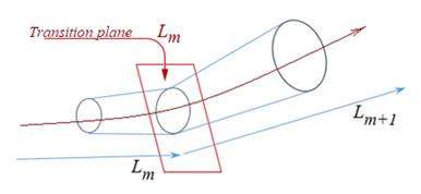
Fig. 2. Parallel
turning of the risk zone to the segments ![]() and
and ![]()
To
implement these principles, different approaches can be proposed; described
below is one of the possible options for a universal algorithm for determining
the control parameters for a joint flight of a group of drones.
6.
ALGORITHM OF THE DECISION-MAKING MECHANISM
Let
us give the rules for determining the flight path and control parameters
depending on the current position of the drone. Suppose that the flight
parameters of the ![]() -th drone at the instant of time
-th drone at the instant of time ![]() , its coordinates
, its coordinates ![]() relative to the
earth, the components of the velocity vector
relative to the
earth, the components of the velocity vector ![]() and the number of
the current direction of movement
and the number of
the current direction of movement ![]() along the
intended trajectory are known. This information can be obtained from the
drone’s navigation system and RAM device.
along the
intended trajectory are known. This information can be obtained from the
drone’s navigation system and RAM device.
Suppose
that the coordinates ![]() and the
components of the velocity vector
and the
components of the velocity vector ![]() of
of ![]() drones located at
the instant
drones located at
the instant ![]() in the immediate
vicinity of the
in the immediate
vicinity of the ![]() -th drone are also known. This information is obtained during
the data exchange between drones. The decision-making system can calculate
the
-th drone are also known. This information is obtained during
the data exchange between drones. The decision-making system can calculate
the ![]() -th drone by carrying out internal numbering
-th drone by carrying out internal numbering ![]() .
.
It
is assumed that the next data exchange will take place after a certain period
of time ![]() , so the drone must determine its control parameters for the
period
, so the drone must determine its control parameters for the
period ![]() based on the
above information.
based on the
above information.
For
simplicity, we will assume that at the beginning of the calculation period ![]() , that is, at the instant
, that is, at the instant ![]() , the radius of the individual zone for all drones is equal
to
, the radius of the individual zone for all drones is equal
to ![]() .
.
Let
us perform a transformation of coordinates to simplify the calculation
formulas. We rotate the coordinate axes around the point ![]() so that the
direction of movement is superimposed on the
so that the
direction of movement is superimposed on the ![]() axis, and the
point
axis, and the
point ![]() on
on ![]() . The transformation formula is written as follows:
. The transformation formula is written as follows:
 ,
,
 , (1)
, (1)
where ![]() ,
, ![]() ,
, ![]() ,
, ![]() , the quantities
, the quantities ![]() are components of
the vector
are components of
the vector ![]() . In formula (1) and in the formulas below, the prime symbol
indicates the new coordinates of the points after transformation. The
transition plane
. In formula (1) and in the formulas below, the prime symbol
indicates the new coordinates of the points after transformation. The
transition plane ![]() in this
transformation is represented as follows:
in this
transformation is represented as follows: ![]() .
.
While
moving along the trajectory, the drone can only move along one segment ![]() until the next
data exchange, in other words, it can fly between the transition planes or
change direction from
until the next
data exchange, in other words, it can fly between the transition planes or
change direction from ![]() to
to ![]() , that is, it can cross the transition plane
, that is, it can cross the transition plane ![]() . Both cases are discussed separately in the following
paragraphs.
. Both cases are discussed separately in the following
paragraphs.
After
calculating the drone velocity, the results must be expressed in the original
coordinate system by inverse transformation (1) and applying a parallel shift
relative to the point ![]() . However, we will not dwell on this transformation.
. However, we will not dwell on this transformation.
6.1. Drone’s flight between transition planes
Let
us first consider the case when the drone flies for a certain time ![]() along the segment
along the segment
![]() . Denote the set of drones flying around the
. Denote the set of drones flying around the ![]() -th drone by
-th drone by ![]() ; the condition
; the condition ![]() is satisfied for
them. Let us write the equation of the cone representing the boundaries of the
risk zone created by each
is satisfied for
them. Let us write the equation of the cone representing the boundaries of the
risk zone created by each ![]() drone. The axial
section of the cone is shown in Fig. 3.
drone. The axial
section of the cone is shown in Fig. 3.
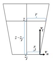
Fig. 3.
Intersection with the risk zone created by the ![]() -th drone along the
-th drone along the ![]() axis
axis
For
each ![]() , the conic surface is the geometric locus of the circle at
the centre point
, the conic surface is the geometric locus of the circle at
the centre point ![]() . Having calculated the radius
. Having calculated the radius ![]() of this circle,
we get
of this circle,
we get ![]() . Then the equation of the risk zone created by the
. Then the equation of the risk zone created by the ![]() -th drone is written as follows:
-th drone is written as follows:
![]() . (2)
. (2)
This formula allows
calculating the points at which the ![]() -th drone flying parallel to the direction
-th drone flying parallel to the direction ![]() will intersect
with the boundaries of the risk zone of the
will intersect
with the boundaries of the risk zone of the ![]() -th drone and finding among them the one closest to the point
-th drone and finding among them the one closest to the point
![]() . The coordinates
. The coordinates ![]() of this point are
calculated as follows:
of this point are
calculated as follows:
![]() . (3)
. (3)
It
is clear that ![]() is the risk zone
created by some
is the risk zone
created by some ![]() -th drone:
-th drone: ![]() . Two different options are possible depending on the values
of the quantities
. Two different options are possible depending on the values
of the quantities ![]() and
and ![]() . Let us consider each of these options separately. Suppose
that,
. Let us consider each of these options separately. Suppose
that,
![]() . (4)
. (4)
In this case, the
velocity at the instant ![]() for the
for the ![]() -th drone can be calculated as
-th drone can be calculated as
![]() , (5)
, (5)
and the drone will move at this
velocity for the entire period until the next data exchange session. If
inequality (3) is violated, other factors must be considered to calculate the
velocity. Suppose that ![]() . This means that if the
. This means that if the ![]() -th drone is flying parallel to the direction
-th drone is flying parallel to the direction ![]() , it will cross the boundaries of the risk zone of the
, it will cross the boundaries of the risk zone of the ![]() -th drone at a point
-th drone at a point ![]() . The
. The ![]() -th drone must change the direction of flight in order not to
get into the risk zone. We will assume that the flight of the
-th drone must change the direction of flight in order not to
get into the risk zone. We will assume that the flight of the ![]() -th drone can be planned along the generatrix (straight line)
of the cone representing the risk zone of the
-th drone can be planned along the generatrix (straight line)
of the cone representing the risk zone of the ![]() -th drone, passing through the point
-th drone, passing through the point ![]() , to the risk zone created by some other drone.
, to the risk zone created by some other drone.
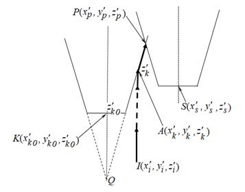
Fig. 4.
Trajectory calculation in case of crossing risk zones
In Fig. 4, this
trajectory is indicated by a bold line. Within the framework of these
possibilities, we will calculate the velocity vector suitable for continuing
the flight of the ![]() -th drone.
-th drone.
First, we find the
coordinates of the point ![]() . Obviously, the point
. Obviously, the point ![]() is located on the
surface of the corresponding cone representing the risk zone of the
is located on the
surface of the corresponding cone representing the risk zone of the ![]() -th drone and satisfies the equation of this cone:
-th drone and satisfies the equation of this cone:
![]() . (6)
. (6)
Let us find the
coordinates of the point of the apex ![]() of cone (6), such
that
of cone (6), such
that ![]() . If we take this into account in equation (4), we get
. If we take this into account in equation (4), we get ![]() . Then the equation of the straight line passing through the
points
. Then the equation of the straight line passing through the
points ![]() and
and ![]() will be:
will be:
 . (7)
. (7)
Now let us find the
coordinates of the point ![]() . The point
. The point ![]() is on line (7),
hence, and by expressing the unknowns
is on line (7),
hence, and by expressing the unknowns ![]() and
and ![]() by
by ![]() and substituting
these expressions into equation (2), we get:
and substituting
these expressions into equation (2), we get:
 ,
,  ,
, ![]() ,
,
![]() . (8)
. (8)
Here  ,
,
 ,
,
 .
.
It is clear from the
essence of the problem that for each ![]() , there is a unique solution within the framework of the
condition
, there is a unique solution within the framework of the
condition ![]() of equation (8).
Then the coordinates of the point
of equation (8).
Then the coordinates of the point ![]() can be calculated
as follows:
can be calculated
as follows:
![]() ,
,  ,
,  (9)
(9)
We can easily see
that if the condition
![]() (10)
(10)
is satisfied, the
drone will continue flying between the transition planes. Under condition (10),
the velocity of the drone in the period ![]() until the next
data exchange can be determined as follows:
until the next
data exchange can be determined as follows:
![]() (11)
(11)
However,
cases of violation of inequality (10) for the quantities ![]() ,
, ![]() , and
, and ![]() are possible:
are possible: ![]() or
or ![]() .
.
Considering
that the velocity ![]() is several times
less than the velocity
is several times
less than the velocity ![]() , in this case the speed can be adjusted so that the drone
continues to fly between the transition planes during
, in this case the speed can be adjusted so that the drone
continues to fly between the transition planes during ![]() . In this case, the velocity of the
. In this case, the velocity of the ![]() -th drone should be calculated as follows:
-th drone should be calculated as follows:
![]() (12)
(12)
6.2. Change of direction during flight
Let
us now consider the case when a drone flying along the segment ![]() between two
successive data exchanges reaches the transition plane and must change
direction. This case involves the fulfilment of the inequality
between two
successive data exchanges reaches the transition plane and must change
direction. This case involves the fulfilment of the inequality ![]() .
.
The
specific characteristic of this case is that the drone must change speed during
the period ![]() . Denote by
. Denote by ![]() and
and ![]() the velocities of
the drone before and after the transition plane
the velocities of
the drone before and after the transition plane ![]() , respectively, and by
, respectively, and by ![]() and
and ![]() the vectors
obtained after applying coordinate transformation (3) of velocities
the vectors
obtained after applying coordinate transformation (3) of velocities ![]() and
and ![]() . In this case, the velocity
. In this case, the velocity ![]() can be calculated
as
can be calculated
as
![]() , (13)
, (13)
this velocity
must be applied during the period ![]() . It is expected that during this time the
. It is expected that during this time the ![]() -th drone will reach the boundary point
-th drone will reach the boundary point ![]() of the transition
plane
of the transition
plane ![]() . The coordinates of this point relative to the original
coordinate system are as follows:
. The coordinates of this point relative to the original
coordinate system are as follows:
![]() (14)
(14)
Let
us determine the coordinates ![]() of the point, at
which each
of the point, at
which each ![]() drone passes
through the transition plane
drone passes
through the transition plane ![]() , and the probable radius of the risk zone created by the
moment of the transition.
, and the probable radius of the risk zone created by the
moment of the transition.
Based
on the coordinates ![]() and the velocity
and the velocity ![]() of the
of the ![]() -th drone at the moment of data exchange, we calculate the
coordinates
-th drone at the moment of data exchange, we calculate the
coordinates ![]() of the point it
needs to reach in the time
of the point it
needs to reach in the time ![]() and the probable
radius
and the probable
radius ![]() of the risk zone
at this time:
of the risk zone
at this time:
![]() (15)
(15)
These
points will be on the transition plane ![]() . Based on the flight plan, starting from this plane, the
drones must change their direction of movement to the direction of the vector
. Based on the flight plan, starting from this plane, the
drones must change their direction of movement to the direction of the vector ![]() . We can calculate the coordinates
. We can calculate the coordinates ![]() of
of ![]() drones relative
to the
drones relative
to the ![]() system. This
requires a transform by applying the matrix
system. This
requires a transform by applying the matrix ![]() to the vector
to the vector ![]() .
.
The movement of the ![]() -th drone, starting from the transition plane
-th drone, starting from the transition plane ![]() , can be considered as movement between the planes
, can be considered as movement between the planes ![]() and
and ![]() . Thus, the velocity
. Thus, the velocity ![]() of the drone for
the time
of the drone for
the time ![]() can be calculated
as in Section 6.1. Besides, it should be remembered that the appropriate
inverse transformations are applied to calculate the velocities
can be calculated
as in Section 6.1. Besides, it should be remembered that the appropriate
inverse transformations are applied to calculate the velocities ![]() and
and ![]() .
.
Finally, note that the values of the quantities ![]() and
and ![]() are determined
based on the drones’ technical indicators and the wind speed in the
flight and operation zone.
are determined
based on the drones’ technical indicators and the wind speed in the
flight and operation zone.
7. CONCLUSION
The proposed
decision-making algorithm shows that each drone participating in a joint flight
can control the safety of its flight based on information received during data
exchange sessions. This is possible since the computational algorithm is
universal and allows calculating the risk zone that other drones around each
drone can create with their movement. This design of the decision-making
mechanism eliminates the need for information about the flight performance of
remote drones. This, in turn, saves energy resources used in the data exchange
between drones.
References
1.
Baxter Jeremy W., Graham S. Horn, Daniel P. Leivers.
2007. Fly-by-Agent: Controlling a Pool of
UAVs via a Multi-Agent System. QinetiQ Ltd Malvern Technology Centre St
Andrews Road. Malvern. UK. P. 232-237.
2.
Rzevski G., P. Skobelev. 2014. Managing Complexity. Published by WIT Press. 217 p.
3.
Кузнецов А.В. 2018. Краткий обзор многоагентных моделей: Управление большими системами. Системный анализ. Выпуск 71. 44 С. [In Russian:
Kuznetsov A.V. An Overview of
Multi-Agent Models: Managing Large Systems. Sistemniy analiz].
4.
Alonso E., N. Karcanias, A.G. Hessami. 2013.
“Multi-agent systems: A new paradigm for Systems of Systems”. Proceedings of the Eighth International
Conference on Systems. Chengdu, China. P. 8-12.
5.
Argel A. Bandala, Elmer P. Dadios, Ryan Rhay P.
Vicerra, and Laurence A. Gan Lim. 2014. “Swarming Algorithm for Unmanned
Aerial Vehicle (UAV) Quadrotors. Swarm Behavior for Aggregation, Foraging,
Formation, and Tracking”. Journal
of Advanced Computational Intelligence and Intelligent Informatics 18(5):
745-750.
6.
Morozova T.Y., I.A. Ivanova, V.V. Nikonov, A.A.
Grishin. 2015. “Improvıng of the drones group control system”.
International Journal of Advanced Studies
5(1): 14-18.
7.
Mitch Campion, Prakash Ranganathan, Saleh Faruque.
“UAV swarm communication and control architectures: a review”. Journal of Unmanned Vehicle Systems
7(2):
93-106.
Received 19.07.2020; accepted in revised form 20.10.2020
![]()
Scientific
Journal of Silesian University of Technology. Series Transport is licensed
under a Creative Commons Attribution 4.0 International License