Article
citation information:
Dižo, J., Blatnický, M., Droździel,
P., Semenov, S., Mikhailov, E., Kurtulík,
J. Strength
analysis of an off-road lorry frame. Scientific
Journal of Silesian University of Technology. Series Transport. 2021, 110, 23-33. ISSN: 0209-3324. DOI: https://doi.org/10.20858/sjsutst.2021.110.2.
Ján DIŽO[1],
Miroslav BLATNICKÝ[2],
Paweł DROŹDZIEL[3],
Stanislav SEMENOV[4], Evgeny MIKHAILOV[5],
Jakub KURTULÍK[6]
STRENGTH
ANALYSIS OF AN OFF-ROAD LORRY FRAME
Summary. The lorry frame is the
main carrying part of a lorry, composed of several components. These components
are connected by joints into one structural unit and it forms the lorry
chassis. The contribution of this article is focused on the strength analyses
of a backbone frame, which is used on an off-road lorry chassis. Strength
analyses are carried out utilising the finite element method. This article
presents a created three-dimensional model of the frame and definition of
boundary conditions (loads, the definition of degrees of freedom) needed for
simulation computations. Results of the numerical calculations are the main
parts of this article. Attention is mainly centred on the distribution of
stresses of the frame under defined loads and its deformations.
Keywords: frame, off-road truck, strength analysis,
finite element method
1. INTRODUCTION
A lorry is a
vehicle whose structure is built to transport goods. However, these vehicles
are used to tow trailers of various kinds as well. Tractors of semitrailers belong to this
group of vehicles.
The chassis of
a lorry is the bottom as well as the carrying part of the vehicle, onto which
the cabin, body and drive-train are mounted. This unit is called the vehicle
underbody. Generally, it is composed of these units [23,36]:
- a frame – the basic carrying part of a lorry chassis,
it is loaded by many kinds of loads reliable fixation of the manipulator to a
chassis without its damage,
- a suspension system – a system of mechanisms, which
transmit loads generated during driving and also as results of dynamic forces,
- axles – it is composed of a pair of wheels with
significant participation on the wheel/road contact,
- a braking system – a system of mechanisms, which serve
for slowing down or stopping of the lorry and ensuring of a lorry in a parking
position,
- a
steering system – a system of mechanisms, which allows changing the
driving direction by means of a steering wheel, a system of linkages and
levers.
Sufficient
rigidity of the main carrying structure of a lorry chassis significantly
affects its driving properties as well as loading of the frame and various
lorry bodies [23,36].
2. THE LORRY
FRAME DESIGN
The
frame is the main carrying part of the lorry, which consists of several
elements. These elements are connected by welds joints, screw connections or
rivet joints to one unit. The main task of a lorry frame is its carrying
ability. The lorry frame design considers among others the power drive-train
type [1-3,13,16,19,34]. Therefore, the frame design
has to ensure sufficient rigidity and be as light as possible [6,24,27,33]. More so, it has to ensure that the centre of
gravity of the lorry be as low as possible, which affects the driving stability
of the lorry. The chassis of the lorry has to allow proper guidance and
ensure sufficient driving comfort.
In
the case of standard lorries, a ladder frame is
usually used to meet the abovementioned requirements in the best way. However,
there are such operational conditions of lorries that
operate in rough terrain conditions, for example, in the building industry as a
tipper, concrete mixer, and likewise in forestry, agriculture, army, rescue
services, etc. In these operating conditions, a lorry is submitted to the
combined loads, which cause in addition to bending loads also torque [17,18,30]. From the frame strength point of view, a ladder
frame structure is no longer able to withstand such difficult combined loads
reliably in comparison with operation on a metalled road. Hence, a backbone
chassis was developed.
The
backbone chassis of a lorry is a type of vehicle chassis, which instead of a
two-dimensional ladder structure, consists of a tubular backbone (usually
circular cross-section). It connects the front and rear axles (lorries are often multi-axle) as well as the suspension
system. The backbone chassis is the most used by the Tatra
Trucks company, which has applied this frame design to its off-road lorries for
many years [22,33].
3. THE
BACKBONE CHASSIS
As
mentioned above, the backbone chassis is the typical characteristic of Tatra off-road lorries. These
lorries are developed mainly for heavy off-road conditions, allowing high passability through terrains, high level of driving
comfort, high speeds over difficult terrain, high levels of vehicle stability
in turns and on slopes, minimum maintenance requirements, minimum possibility
of drive-train damages, etc. [22,33].
The
backbone chassis consists of these units:
- a central load-carrying tube,
- axles with independently suspended swinging half-axles
bolted together into a single unit.
The
central load-carrying tube can withstand high torsion and bending loads,
protecting lorry bodies from transmitted loads; its modular system enables the
assembly from two to multi-axle lorries with the
optional all-wheel drive. Further, the shafts of a drive-train system are
situated in the central tube, which protects them from external effects. Such a
technical solution provides high durability together with low maintenance costs
[22].
Off-road
lorries Tatra equipped with
the backbone chassis use independently suspended half-axles. In the basic
version, they are always driven and combined with locks. Differentials are
placed outside the axles in the central loading tube. Axles are equipped with a
pneumatic drum brake system. There are several load-bearing capacity versions
of this chassis. Lighter versions are equipped with a mechanical suspension
system, which consists either of torsion rods for versions with a single
steered front axle or of leaf springs for versions with two steered axles.
Heavier versions are equipped with a pneumatic suspension system, which
provides completely different driving characteristics. All kinds of suspension
systems are combined with telescopic dampers or torsion rods [22,33].
Figure
1 shows the Tatra off-road lorry whose frame is
analysed below.
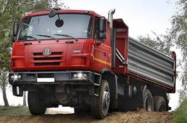
Fig. 1. Tatra off-road lorry [33]
4. STRENGTH
ANALYSIS OF THE BACKBONE CHASSIS FRAME
The
main purpose of the strength analysis of the frame is to determine the stress
distribution on the frame structure to identify critical locations with stress
concentration [9].
The
analysed frame is the main carrying part of the Tatra
off-road lorry (Fig. 1), which is built to transport goods up to the load
capacity of 15,700 kg. The total weight of the vehicle is 26,000 kg.
Fig. 2. A
three-dimensional model of the analysed frame
The
central load-carrying tube is thick-walled. It is combined with cross walls and
two longitudinal U profiles.
Profiles
and other components are made of structural steel S355J0
whose mechanical properties are listed in Tab. 1.
Tab.
1
Basic mechanical properties
of structural steel S355J0
|
Material |
Yield strength |
Ultimate strength |
Density |
Young’s modulus |
|
Structural steel |
355 |
470-630 |
7850 |
210,000 |
Strength
analyses of the frame were carried out in the ANSYS
software package [4,35]. It works based on the
finite element method (FEM) [26,28,31]. In this
software, it is possible to perform static analyses [11], modal [14,32] and other types of analyses of individual components [10,14,32],
structural unit and even entire mechanical systems [7,12].
The
realisation of analyses consists of several defined steps. First, the volume
geometry was created and contact couples between parts of the model were
defined. Afterwards, the FEM mesh was generated. Figure 3 depicts a mesh
model of the frame.
The
mesh model composed by quadratic tetrahedron elements with a size of
10 mm. Number of elements was 789,491 and number of nodes 1,484,614.
Another
step in analysing the frame was the definition of boundary conditions. Loads were
defined in the centres of gravity (CoG) as following
(Fig. 4):
- an empty tipping body: 25,000 N a central load-carrying
tube,
- a fully loaded tipping body: 157,000 N,
- an engine: 13,500 N,
- a cabin: 4,500 N.
The
strength analyses were performed for two loading states, that is, for an empty
carriage body and a fully loaded carriage body. When the empty carriage body is
considered, only the net weight of the tipping body acts on the analysed
structure.
|
|
|
|
a) |
b) |
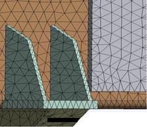
Fig. 3. (a) A
mesh model of the analysed frame, (b) FEM mesh detail
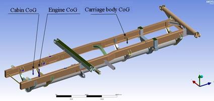
Fig. 4. Acting
loads on the analysed frame
Results
of strength analyses for the empty tipping body are shown in Fig. 5
and 6.
Fig. 5.
Distribution of von Misses stresses in the frame structure – the empty
tipping body
Fig. 6. Total
deflection of the frame structure – the empty tipping body
As
can be seen, the greatest value of the reduced stress (calculated according to
the von Misses hypothesis) is identified in the locations of torsion rods
joints in the plate and the location of the plate mounting to the central
tube. The reduced stress reached a value of 140.98 MPa (Fig. 5).
The
total deflection achieved in the frame structure for the first load case, that
is, for the empty tipping body, is 4.12 mm. It is detected in the
front part of the frame (Fig. 6).
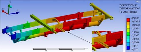
Fig.
7. Vertical deflection of the frame structure – the empty tipping body
Figure 7
shows the deflection of the frame structure for the first load case in the vertical
direction (y-axis). It shows that the
most loaded part of the frame is identified in the tipping body location,
between the location of rear leaf springs mounting and the torsion rods plate.
A part of the longitudinal profiles as well as triangular cross walls are
also loaded.
The
second loading case is considered for the fully loaded tipping body as
aforementioned. Results of strength analyses are shown in Fig. 8 and
Fig. 9.
Based
on the reached results, the greatest value of the reduced stress is similarly
detected in the same location as in the case of the empty tipping body.
However, in the second loading case, this stress reached the value of
253.36 MPa (Fig. 8).
The
total deflection of the frame structure for the second loading case reached the
value of 6.36 mm (Fig. 9). It is also detected in the front part of
the frame structure.
The
maximal value of 0.74 mm of the vertical deflection (y-direction) of the frame structure was identified in the rear leaf
springs mounting location (Fig. 10).
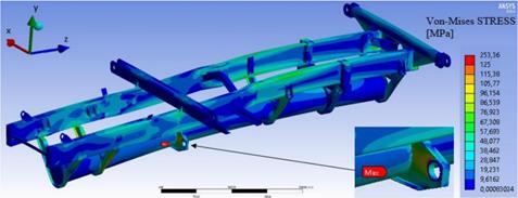
Fig. 8.
Distribution of von Misses stresses in the frame structure
– the fully loaded tipping body
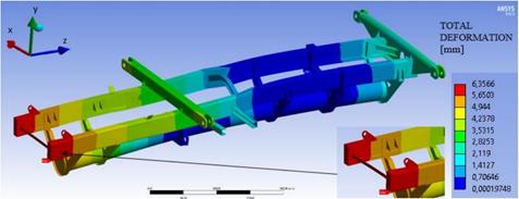
Fig. 9. Total
deflection of the frame structure – the fully loaded tipping body
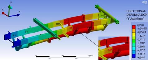
Fig. 10.
Vertical deflection of the frame structure – the fully loaded tipping
body
From
shown results of the strength analyses of the frame structure for the first and
second loading cases, it is obvious, that the value of the reduced stress
calculated according to the von Misses hypothesis increased from the value of
140.98 MPa (the empty tipping body) to the value of 253.36 MPa (the fully
loaded tipping body).
The
determined value of the total deflection in the critical location of the frame
structure increased from the value of 4.12 mm (the empty tipping body) to the
value of 6.36 mm (the fully loaded tipping body).
The
value of the vertical deflection (y direction) also increased, namely from the
value of 0.38 mm (the empty tipping body) to the value of 0.74 mm.
The
yield of strength (Re) of the steel S355J0 used for
the frame structure production is 355 MPa. The maximal value of the
determined value is 253.36 MPa. Thus, the performed static analyses of the
frame structure have shown that it meets the requirements of rigidity and
safety material within the safety factor of 1.4.
However,
the tipping lorry Tatra is designed for heavy
off-road operational conditions. Therefore, the chassis including the frame is
loaded with dynamic loads. Their characteristics, such amplitude and frequency
are stochastic and they will cause different loads in comparison with performed
static analyses [5,20,21]. Hence, future research in
this field should be focused on obtaining input data, which will simulate more
realistic loading of the frame structure. There are mainly loads in the
location of axles mounting, where wheel forces will act on the frame. Further,
efforts will be made to creating a virtual multibody model (MBS model) of the
lorry chassis. It is possible to expand the MBS model using the presented FEM
model of the frame [15,25,37], input dynamic loads to
the structure and investigate its behaviour under these defined loads.
5. CONCLUSION
The
solution of the presented problem consists of obtaining input data from a
customer. Based on these data, the engineering design and functional solution
of the manipulator were created. The important task was the design of the
compressor setting, which has to meet all requirements in term of its
dimensions and the possibility of compensation of all inaccuracies. Safety of
the device, protection of health and operator and ergonomic parameters were
other important aspects of the design. Compliance with the relevant standards
and internal regulations of the customer was a matter of course. Designs of the
rotating part of the manipulator, the control panel, the travel and the
pneumatic parts of the manipulator were realised together with the compliance
of the customer-required components from precisely specified manufacturers. The
next step in solving this problem would be the design of the pneumatic brake,
the selection of air treatment equipment, the creation of the pneumatic circuit
diagram, the FEM simulation of the steel plate, the adjustment mechanism and
the RPS pin console.
Source of
funding
This work was supported by the Cultural and
Educational Grant Agency of the Ministry of Education of the Slovak Republic in
the project No. KEGA 023ŽU-4/2020: Development of advanced virtual models
for studying and investigation of transport means operation characteristics.
References
1.
Barta Dalibor, Martin Mruzek,
Martin Kendra, Paweł Kordos,
Leszek Krzywonos. 2016. “Using of non-conventional
fuels in hybrid vehicle drives”. Advanced
in Science and Technology – Research Journal 10(32): 240-247. ISSN:
2299-8624. DOI: 10.12913/22998624/65108.
2.
Barta Dalibor,
Martin Mruzek, Robert Labuda,
Tomas Skrucany, Leszek Gardynski. 2018. “Possibility of increasing vehicle
energy balance using coasting”. Advances
in Science and Technology – Research Journal 12(1): 228-235. ISSN:
2299-8624. DOI: 10.12913/22998624/86215.
3.
Figlus Tomasz, Łukasz Kuczyński.
2018. “Selection of a
semi-trailer for the haulage of long oversize loads, taking into account an
analysis of operational damage”. XI International
Science-Technical Conference Automotive Safety. IEEE Proceedings Paper. DOI: 10.1109/AUTOSAFE.2018.8373342.
4.
Fomin Oleksij,
Juraj Gerlici, Alyona Lovska, Kateryna Kravchenko, Yuliia Fomina, Tomas Lack. 2019.
“Determination of the strength of the containers fittings of a flat wagon
loaded with containers”. 9th
International Scientific Conference on Research and Development of Mechanical
Elements and Systems IRMES 2019. University of Kragujevac. 5-7 September, Kragujevac,
Serbia. ISSN: 1757-8981.
DOI: 10.1088/1757-899X/659/1/012056.
5.
Fomin Oleksij,
Juraj Gerlici, Alyona Lovskaya, Kateryna Kravchenko, Oleksii Burlutski, Vladimir
Hauser. 2019. “Peculiarities of the mathematical modelling of dynamic
loading on containers in flat wagons transportation”. MATEC Web of Conferences 254. ISSN: 2261-1009. DOI:
10.1051/matecconf/201925402039.
6.
Gardynski Leszek,
Jacek Caban, Dalibor Barta. 2018. “Research of composite materials used in
the construction of vehicle bodywork”. Advanced in Science and Technology – Research Journal 12(3):
181-187. ISSN: 2299-8624. DOI:
10.12913/22998624/92096.
7.
Gerlici Juraj,
Tomas Lack, Jozef Harusinec.
2014. “Development of test stand prototype for rail vehicles brake
components testing”. Communications
– Scientific Letters of the University of Zilina
(Komunikacie) 16(3): 27-32. ISSN:
1335-4205.
8.
Gerlici Juraj,
Tomas Lack, Jozef Harušinec.
2012. “Test stand properties analysis for wheels tread wear in accordance
to the laboratory simulated railway operation”. Proceedings of the 13th Mini Conference on Vehicle System
Dynamics, Identification and Anomalies VSDIA 2012:
157-165. Budapest University of Technology and Economics. 5-7 November,
Budapest, Hungary. ISBN: 978-963313102-2.
9.
Gülenç B., H. Kocaman, B. Çevik, A. Durgutlu, T. Fındık.
2016. “The effect of cold and hot reformation process to mechanical
properties of deformed automobile chassis material”. Mechanika 22(5): 376-379.
10.
Handrik Marian, Peter Kopas, Vladmimir Baniari, Milan Vasko, Milan Saga.
2017. “Analysis of stress and strain of fatigue specimens localized in
the cross-sectional area of the gauge section testing on bi-axial fatigue
machine loaded in the high-cycle fatigue region”. Procedia Engineering 177: 516-519. ISSN: 1877-7058. DOI: 10.1016/j.proeng.2017.02.254.
11.
Jakubovicova Lenka,
Alzbeta Sapietova, Jan Moravec. 2018. “Static analysis of transmission tower
beam structure”. MATEC Web of Conference 244.
ISSN: 2261-236X. DOI:
10.1051/matecconf/201824401011.
12.
Jakubovicova Lenka,
Peter Zavadinka, Jan Jakubovic.
2016. “Transport duty cycle measurement of hybrid drive unit for mixing
drum”. Advanced Mechatronics
Solutions 393: 219-224. ISSN: 2194-5357. DOI:
10.1007/978-3-319-23923-1_33.
13.
Kalincak Daniel, Lubos Bartik, Juraj
Grencik. 2012. “The hybrid traction – the
way of fuel utilization improvement”. Facta Universitas – Series Mechanical
Engineering 10(2): 163-170. ISSN: 0354-2025.
14.
Klimenda Frantisek, Josef Soukup, Milan Zmindak, Blanka Skocilasova. 2018.
“Dissemination of shock waves in thin isotropic plates”. MATEC Web of Conferences 254. ISSN: 2261-236X. DOI: 10.1051/matecconf/201925405005.
15.
Kostrzewski Mariusz.
2018. “Analysis of selected acceleration signals measurements obtained
during supervised service conditions – study of hitherto approach”.
Journal of Vibroengineering
20(4): 1850-1866. ISSN: 1392-8716. DOI: 10.21595/jve.2018.19367.
16.
Kozioł, Mateusz, Tomasz Figlus. 2015. “Failure Progress of 3D Reinforced GFRP Laminate during Static Bending, Evaluated by Means of
Acoustic Emission and Vibrations Analysis”. Materials 8: 8751-8767. DOI: 10.3390/ma8125490.
17.
Kravchenko Alexander, Olga Sakhno, Alexander Lukichov. 2014.
“Research of dynamics of tire wear of trucks and prognostication of their
service life”. Transport Problems
7(4): 85-94. ISSN: 1896-0596.
18.
Kravchenko Alexander, Olga Sakhno, Alexander Lukichov. 2014.
“Trucks tires resource controlling by control of process of their
wearing-out”. Transport Problems
9(1): 83-93. ISSN: 1896-0596.
19.
Labuda Robert, Dalibor Barta, Andrej Kovalcik. 2010. “Effective use of the braking effect of
vehicle drivetrain at deceleration”. XLI.
International Scientific Conference of Czech and Slovak University Departments
and Institutions Dealing with the Research of Internal Combustion Engines (KOKA 2020): 206-211. Technical University Liberec.
06-07 September, Liberec, Czech Republic.
20.
Leitner Bohus,
Lucia Figuli. 2018. “Fatigue life prediction of
mechanical structures under stochastic loading”. MATEC Web of Conferences 157. ISSN: 2261-1009. DOI: 10.1051/matecconf/201815702024.
21.
Leitner Bohus.
2010. “A new approach to identification and modelling of machines dynamic
systems behaviour”. Proceedings of
the 19th International Scientific Conference on Transport Means
TRANSPORT MEANS 2010: 17-20. Kaunas University of Technology. 21-22
October, Kaunas, Lithuania. ISSN: 1822-296X.
22.
Leitner Bohuš.
2014. “Fatigue damage analysis and fatigue life prediction of lorry frame
under random excitation”. 18th
International Conference on Transport Means Transport Means 2014: 9-14.
Kaunas University of Technology. 23-24 October, Kaunas, Lithuania. ISBN: 1822-296X.
23.
Liščák Štefan,
Rostislav Matějka, Vladimír Rievaj, Marián Šulgan. 2006. Chassis of road vehicles (In Slovak). Žilina: University of Žilina.
ISBN: 80-8070-588-7.
24.
Melaika M., S. Nagurnas, R. Pečeliūnas,
N. Višniakov, G. Garbinčius.
2013. “Investigation on distribution of stresses in steel and aluminium
alloy arms of a car suspension system”. Mechanika 19(6): 632-640.
25.
Melnik Rafal,
Bogdan Sowinski. 2017. “Analysis of dynamics of
a metro vehicle model differential wheelsets”. Transport Problems 12(3): 113-124. ISSN: 1896-0596. DOI: 10.20858/tp.2017.12.3.11.
26.
Ren Yuan, Yongchang Yu, Binbin Zhao, Chuanhui Fan, He Li. 2017. “Finite element analysis and optimal
design for the frame of SX360 dump trucks”. Procedia Engineering 174: 638-647. ISSN:
1877-7058. DOI: 10.1016/j.proeng.2017.01.201.
27.
Savkin Alexey Nikolaevich, Alexander Gorobtsov,
KA Badikov. 2016. “Estimation of truck frame
fatigue life under service loading”. Procedia
Engineering 150: 318-323. ISSN: 1877-7058. DOI:
10.1016/j.proeng.2016.07.020.
28.
Stastniak Pavol,
Lukas Smetanka, Marian Moravcik.
2018. “Structural analysis of a main construction assemblies of the
new wagon prototype type Zans.” Manufacturing Technology 18(3): 510-517.
ISSN: 1213-2489. DOI: 10.21062/ujep/130.2018/a/1213-2489/MT/18/3/510.
29.
Suchanek Andrej, Jozef Harusinec, Maria Loulova, Peter Strazovec. 2018.
“Analysis of the distribution of temperature fields in the braked railway
wheel”. MATEC Web of Conference 157. ISSN: 2261-1009.
DOI: 10.1051/matecconf/201815702048.
30.
Suda Yoshihiro, Juraj Grencik. 1996. “The
mechanism of enhanced curving performance of unsymmetric
suspension trucks under acting traction/brake torque”. Vehicle System Dynamics 25 (SUPPL): 629-640. ISSN: 0042-3114. DOI: 10.1080/00423119608969225.
31.
Supardjo, Agus
Dwi Anggono,
Tri Widodo Besar. 2018. “Finite element
analysis of truck frame by using CATIA V5”. Proceeding
of the 4th International Conference on Engineering, Technology and
Industrial Application ICETIA 2017. Universitas Muhammandiyah
Surakarta. 13-14 December, Surakatra, Indonesia.
ISSN: 1551-7616. DOI: 10.1063/1.5042949.
32.
Svoboda Martin, Vaclav Schmid,
Josef Soukup, Milan Sapieta.
2018. “Modal analysis of the vehicle model”. Springer Proceedings in Mathematics & Statistics 249: 351-362.
ISSN: 2194-1009. DOI: 10.1007/978-3-319-96601-4_32.
33.
Tatra vehicle design.
Available at:
https://www.tatratrucks.com/why-tatra/tatra-vehicle-design/tatra-vehicle-design-1/.
34.
Varjan Pavol,
Jozef Gnap, Pavol Ďurana, Mariusz Kostrzewski. 2019.
“Research on the relationship between transport performance in road
freight transport and revenues from excise duty on diesel fuel in selected
European countries”. Transportation
Research Procedia 40: 1216-1223. ISSN: 2352-1457. DOI: 10.1016/j.trpro.2019.07.169.
35.
Vatulia Glib, Anatoliy Falendysh, Yevhen Orel, Mikhailo Pavliuchenkov. 2017. “Structural improvements in a
tank wagon with modern software packages”. 10th International Scientific Conference on
Transportation Science and Technology TRANSBALTICA
2017: 301-307. Vilnius Gediminas University of
Technology.
04-05 May, Vilnius, Lithuania. ISSN: 1877-7058. DOI:
10.1016/j.proeng.2017.04.379.
36.
Vlk František.
2006. Chassis of engine vehicles (In
Czech). Brno: František Vlk
Publishing. ISBN: 80-239-6464-X.
37.
Weyssenhoff Andrzej, Michal Opala, Seweryn Koziak, Rafal Melnik.
2019. “Characteristics and investigation of selected manufacturing
defects of passenger car tires”. Transportation
Research Procedia 40: 119-126. ISSN: 2352-1457. DOI: 10.1016/j.trpro.2019.07.020.
Received 17.08.2020; accepted in revised form 12.11.2020
![]()
Scientific
Journal of Silesian University of Technology. Series Transport is licensed
under a Creative Commons Attribution 4.0 International License