Article
citation information:
Cieśla, M., Opasiak, T. Mining machines elements
packing and securing on platform container. Scientific
Journal of Silesian University of Technology. Series Transport. 2021, 110, 05-21. ISSN: 0209-3324. DOI: https://doi.org/10.20858/sjsutst.2021.110.1.
Maria CIEŚLA[1],
Tadeusz OPASIAK[2]
MINING
MACHINES ELEMENTS PACKING AND SECURING ON PLATFORM CONTAINER
Summary. The scientific purpose
of this paper was to analyse the problem related to intermodal transportation
of mining components packed in containers or other cargo transport units
coupled with the problem of its proper securing. In this article, the issue of
exposing the load to the effects of inertia forces which might cause
unintentional movement is presented. The methods of securing the heavy load in
cargo transport units are reviewed in the context of cargo immobilisation
possibilities while reducing the load sensitivity to mechanical forces. The
research part of this article presents the methods of packing and securing an
atypical load, which is a part of a mining machine weighing 18t. This paper
presents the results of calculations of inertia forces acting on the
transported cargo, packed on a container platform. Based on the results,
the cross fixing method was selected to secure the cargo and further decisions
were made on the type and quantity of conveyor lashings necessary for the safe
and correct carriage of the atypical load.
Keywords: mining machines securing, lashing selection,
platform container
1. INTRODUCTION
Road transport
vehicles are characterised by widespread availability, flexibility and speed.
Due to the very large diversity of goods and means of transport used, the
method of attachment must be adapted to the needs every time to maintain
maximum safety for both the traffic load, vehicle and other road users.
However, the results of vehicle inspections show that some of the loads carried
are not properly secured on road vehicles. It is estimated that about 25% of
accidents involving trucks result from improper cargo protection [2, 20].
The issue of
freight transport security deserves special attention due to the huge, negative
consequences that entail, for example, losing a heavy load during an emergency
and uncontrolled situation. It is important to determine the impact of
unsecured or incorrectly secured load packages in any transport unit on the
effects in the form of collisions and accidents. More so, it is worth realising
that responsibility for errors arising from unsecured loads, which, according
to the European and global law, concerns all participants in the transport
chain. Shippers, who usually pack goods for shipments are similarly responsible
for the loads’ safety in their supply chains [1, 2, 13, 19]. Human error
[2-4, 6, 14, 21] and the problem of causality [7] in the analysis of accidents
are widely investigated, providing enrichment of knowledge about methods,
procedures and tools allowing incident and accident prevention or prediction [8].
The knowledge
of cargo and packing dynamics has improved over the years [10]. Although there
are many methods and tools supporting cargo security [5, 22], during road
transportation, packed cargo is exposed to other independent random factors.
One is the impact of inertia forces that can cause movement of packaged goods.
The direction of these forces depends on changes in the speed vector of the
vehicle, and in particular, in the direction of the vehicle during braking,
towards the rear of the vehicle during the start-up, or facing transversely to
the vehicle when the transport vehicle is travelling on a curvilinear arc. In
each of the specified cases, the vector of inertia forces takes the direction
of the acceleration vector and its value is proportional to the value of the
vector resulting from the velocity. In addition, the load can be influenced by
the forces resulting from the movement of the vehicle on the road with its
significant inclination and uneven ground. However, there are some studies
focused on non-lashing cargo securing methods [9, 11, 24].
Load
sensitivities for mechanical effects can be reduced by appropriate
immobilisation, that is, by employing suitable fastening elements. These
fastening elements include fastening belts, chain hoists, rope hoists, locking
elements, etc.
By selecting
appropriate methods and tools for securing specific loads, it should be
emphasised, that improper attachment of the load could result in a dangerous
road situation; often resulting in loss of life or health of its participants.
Currently,
legal acts are regulating the requirements for proper protection of loads
during their transportation. Within the European Union, the legal issue of
cargo carriage is regulated by EN-12195. In many countries, this standard has
been obligatory for many years, but still not fully respected by the road
hauliers community. However, it is known that the responsibility for properly
securing the transported cargo lies directly on the carrier. Surprisingly, the
fact remains that dangerous road events still occur, which can be traced to
erroneously secured loads, the reason being lack of knowledge of the problem.
These errors often arise at the loading stage and are often identified for
non-typical loads. Load conditions are extremely important for assessing the
carrier's reliability [12, 15, 23].
This article
presents a practical example of correct safeguarding of an atypical, 18t load
based on the calculated inertia forces acting on the transported cargo that is
placed on the container platform. Securing the load was done with the cross
fixing method.
2.
NECESSITY OF CARGO IMMOBILISATION
Transportation
of machines or other devices, which are usually oversized or extremely
expensive, consists of complex actions involving the movement of cargo and
handling operations (loading, unloading and reloading). Such transportation requires
specialised knowledge and equipment and every part of the process should be
carefully planned [15].
Fig.
1 presents the essential elements of significant transportation process
planning. All elements indicated, affect the quality of the transported goods
and the quality of transport service.
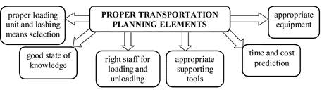
Fig. 1. The basic elements of proper and safe transportation planning
When
planning both recurring and single shipments, a proper loading unit must be
selected and adapted to the type of load and the mode of transport. The
appropriate choice of means of transport (loading unit) for the shipment is
influenced by several factors, such as mode of transport, type of package,
delivery time, density and quantity of the product, requirements for previous
loads, additional equipment, load and securing type or vulnerability to
the external transport conditions. Some of them refer to the conditions of
transporting goods, and others to the packages or transport units used or even
to the requirements for equipment and supplies [16].
Requirements
for equipment, supplies, and loading/unloading technique should be confirmed
with the carrier to maximise optimisation [12]. This information will help the
carrier easily organise the transportation of specific goods. For some
products, the package or transport unit used must be specially designed to
maintain safety in the transport process. Ensuring safe transport depends on
many factors, including the correct selection of packaging or transport unit
and fixing means [17]. The decision, however, depends on the forces acting on
the load.
2.1.
Proper load securing
Securing
of loads during transport is reduced to balance the inertial forces acting on
the load when the vehicle is moving during
acceleration, braking, cornering or overtaking manoeuvres, etc. The
frictional forces that occur between the surface of the cargo floor of the
vehicle and the lower surface of the load are often insufficient to ensure that
the load does not move. Vertical movements of the load during driving due to
bumps and vibrations reduce the frictional force resulting from contact. For
fixing packages or loads on vehicles, elastic belts, ropes or chains, equipped
with mechanical tensioning devices (latches, clamps, stabilisers tensioners)
are used. The carrier responsible for securing the cargo before transport
selects the appropriate number of fixing lashings by him or herself,
considering the mass of the transported load and its external dimensions, which
affects the choice of type and strength parameters of the fastening elements as
the basis of the decision. These principles refer to different types of
cargoes, except liquid cargoes and gas. The most common cargoes, their stowage
and calculation are container cargoes, reefer cargoes, bulk cargoes including
grain and grain products, heavy lift cargoes, timber cargoes, steel cargoes and
ro-ro cargoes [18].
The
appropriate computational analysis is required to determine the forces
transmitted by the load securing elements. This analysis must consider the
following three basic situations that are usually encountered during road
transport:
− braking of the vehicle while
driving straight ahead,
− braking on the curve of the road
when the load on the vehicle is inertia, both in the driving direction and in
the lateral direction outside the arc,
− intensive braking of the vehicle
when driving straight ahead on uneven surfaces,
− vibration of the vehicle causing
reduction of the load pressing the load to the floor of the cargo hold, thus
reducing the friction between the cargo and the cargo area.
These
problems refer not only to the cargo packed inside transport units but also to the
transport units themselves (egg containers) that have to be properly secured [19].
2.2. Forces
acting on packed cargo in transport
The
maximum acceleration
acting on the load while driving is determined by the acceleration product g and the acceleration factor C as defined in the standards [3, 19].
Acceleration factors are regulated by European standards and the IMO, and
differences in values are detailed in Table 1. In addition to the guidelines
contained in the IMO, the United Nations Economic Commission for Europe
recommends using the EN 12195-1 standard in which it has drawn up the European
Commission guidelines on cargo security, and the differences between those
provisions are shown in Fig. 2. Many experts from the European Commission and
scientists worked to elaborate parameters acceptable to obtain the European
standard [1, 3, 19].
Fig.
2. Accelerations acting on the transported cargo in road transport according to
standards
The
German standard, VDI2700, explains the basic forces acting on the cargo, its
proper location and the practical way of installing the fastening devices.
Standard VDI2701 refers to load fixing devices, and the VDI2702 standard
describes the method of calculating the forces required to correctly load the
most common loads with no complicated shapes. Compared to
the EN 12195-1:2010 standard, VDI is more
complex with typical examples and drawings showing how a particular type of
transported cargo should be properly secured, for example, metal circles, large
panes of glass, steel pipes, etc.
Road
Transport Inspection and similar institutions
checks are very accurate at the security control of cargo, which greatly
contributes to the improvement of safety in international transport since the
vehicle with improperly secured load is stopped in the parking lot and cannot
set out on a further route until it is rectified. This
is related to vehicle downtime and the need to supply the driver with
appropriate fastening means.
Tab.
1
Normalised
values of the acceleration factor C depending on
the direction of inertia of the
moving vehicle
|
Direction of inertia force |
Acceleration
factor value C |
|
|
IMO |
EN
12195-1 |
|
|
In the direction of the longitudinal movement,
at the moment of braking |
C=1.0 |
C=0.8 |
|
In the direction of the opposite longitudinal
movement at the moment of starting |
C=0.5 |
C=0.5
(+0.1) |
|
In the transverse direction when driving on
the arc of the road |
||
|
Vertical direction when driving on uneven
roads |
C=1.0 |
C=1.0 |
3. CONTAINER
PACKING AND SECURING OF MINING CONVEYOR
– A CASE STUDY
3.1.
Load characteristics
The
case study in view is based on an order received by a multimodal
transport operator from a global mining machinery and equipment manufacturer
specialising in underground mining, open-pit mining, and bulk cargo transport
and handling. The subject of the order was the transport from Poland to Jakarta
Port in Indonesia of five coal conveyors to carry coal in the open-pit mines.
The whole project was divided into four stages, including multimodal transport.
The transported machines were divided into 122 separate load units due to their
size. Transport took place on standard semi-trailers: tarpaulin of dimensions:
width: 2.48 m, height: 2.70 m, length of 13.6 m and container and cargo units
40 feet plate-type Flat Rack Containers or multi-purpose containers.
The
untypical load analysed in detail in this article is the opencast mine belt
conveyor system of which loading by a reach stacker is shown in Fig. 3. The mass
of the load is mL=18 000 kg, width d=3.2 m, height h=3.0 m and length
l=9.5 m.
3.2.
Selection of cargo securing method
When
attaching an atypical load to an open container
platform, it is important to consider inertia forces acting on the cargo during
its transportation. The theoretically transported cargo can be immobilised by
belt anchorage or appropriate cargo blocking. The load
should be secured by the carrier with elastic fastening elements using
the strap cross fixing method shown in Fig. 4. The surface of the loading platform is made of
painted steel sheet on which wooden supports are laid. Basing on the friction
coefficient table, the coefficient of friction μ=0.20 was calculated for
further estimations. Each of the fastening elements was stressed by a perforce
of Fw=1000 N.

Fig.
3. Belt conveyor drive system for open-pit mine loading process
Fig.
4. Fastening of cargo on a 40 ft Flat Track container
Atypical load should be secured with ten lashing elements in the form of straps (1,
1’, 2, 2’, 3, 3’, 4, 4’, 5, 5’) according to the
scheme in Fig. 5.
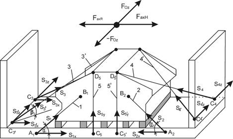
Fig.
5. Scheme of belt conveyor system securing method on a container platform
For further
analysis, the following indications were determined according to Fig. 5:
− S1, S1’,
S2, S2’, S3, S3’, S4,
S4’ – tensile forces in fixed lashings no.
1,1’,2,2’,3,3’,4,4’;
− S1x, S1x’,
S2x, S2x’, S3x, S3x’, S4x,
S4x’ – force components of S1, S1’,
S2, S2’, S3, S3’, S4,
S4’, acting respectively in the directions of the axis Ox;
− S3z, S3z’,
S4z, S4z’ – force components of S3,
S3’, S4, S4’ acting respectively
in the directions of the axis Oz;
− S1y, S1y’,
S2y, S2y’ – force components of S1,
S1’, S2, S2’, acting respectively
in the directions of the axis Oy;
− α1, α2
– angles between the lashings S1, S1’, S2,
S2’ and the plane of a container platform;
− β3x, β3’x, β4x, β4’x,–
angles between the axis Ox and the lashings projection on the
platform plane;
− β3z, β3’z, β4z, β4’z
– angles between the axis Oz and the lashings projection on
the platform plane.
3.3. Forces acting on the transported cargo
In the
longitudinal direction, the Fax inertia force acts on the load that
occurs during the braking FaxH and the acceleration FaxR
of the vehicle. While driving along the curvilinear path, centrifugal force Foz
is created, because the uneven surface of the road is a source of inertial
force Fby acting vertically. The values of
the forces of inertia are calculated as the product of the acceleration of
gravity C and derived from the load being transported QL according to the formula:
![]() (1)
(1)
The
values of Cxyz acceleration factors are normalised for the different
directions of inertial forces and the values were shown in Table 1 according to
the European standard.
3.4.
Calculation and selection of lashings for conveyor attachment on a container
platform
The cargo on
the container platform of the vehicle should be protected against slipping
while driving, to ensure the safety of the driver, the traffic and to secure
the load from possible damage. Different methods of fixing cargo on means of
transport are used in transport. The basic ones are: blocking, anchoring using
lashing, increasing the value of friction force of the load on the floor of the
body by the belt lashing method. In practice, combinations of these methods are
usually used. The purpose of this combination is to improve the efficiency of
the loaded cargo.
For
the mounting of the conveyor belt drive system, the cross anchoring method with
belt lashing was used. The cross anchoring method allows
attaching a heavyweight load using only four lashings that secure the load from
moving in both the transverse and the longitudinal directions. However, a
necessary condition for using this kind of protection is that the load has
special handles to fix the lashings used.
The selection
of cross anchoring lashing is to determine the minimum value of the LC lashing
capacity for each of the lashes located at the front (LPp) and the
back (LCt) of the container platform. To determine the lashing
capacity, it is necessary to analyse the inertia forces of the transported load
at the time of the most unfavourable conditions (like roadblock overcoming)
occurring in road transport. During breaking, the inertia force Faxh,
is determined by the following relation (2) (Fig. 6) and is calculated as
follows:
![]() (2)
(2)
where: ax - accelerated deceleration
at braking, mL - load mass.
Therefore,
while braking the Faxh inertia
force acts on the load with 141 264 N.
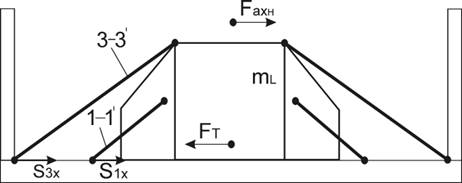
Fig.
6. Diagram showing forces reaction at the moment of braking
At the moment
of braking, the load is secured with 1, 1', and 3, 3’ lashings. In addition to FaxH
inertial force also opposes the FT
frictional force between the surface of the platform container and the wooden
sleepers under load. The friction force FT (3) is directed
opposite to the force causing the load shifting according to the relation (Fig.
7).
![]() (3)
(3)
For wooden
beams and metal substrates, the coefficient of friction is in the range
µ=0.2-0.5. The most unfavourable value was considered, that is,
µ=0.2. In the case of cargo resting horizontally on the platform, the
load force N and the gravity of the load G are equal (N=G). Apart from these
forces, in this case, the load was additionally compressed by the 5 and
5’ belt tension. Then on the force of pressure N, in addition to the
gravity G, there is also the pressing force Pn, derived from the
tension of the belts 5 and 5’. Thus, the load pressure on the substrate,
including the fixing straps, is:
![]() (4)
(4)
where: Pn - additional force pressing
the load to the cargo platform of the container.
Belt
tensioners increase the clamping force by an
additional value of Pn = 5000 N (standard tension force STF). After substituting the appropriate size and calculating the
frictional force, FT has the following
value:
![]() =36 316
N (5)
=36 316
N (5)
The frictional
force, after considering the forces from the load and the pressing straps, is FT=36 316
N. At the moment of braking, after taking into account the force of friction of
the load and the pressing of the belts, the final inertial force FaxH
is applied to the transported load with the following values according to the
following relation:
![]() (6)
(6)
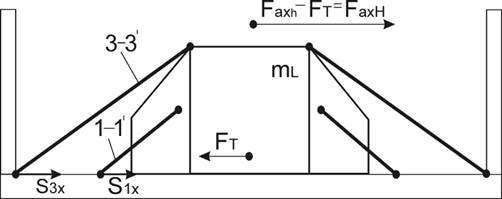
Fig.
7. Scheme of inertia force at the moment of braking
The
resulting value
(6) is inertial force FaxH that acts directly on the load at the time of braking and to
which should be secured with lashing equipment no. 3, 3’ and 1, 1’.
After determining the magnitude of the inertia force acting on the load at the
moment of deceleration, the centrifugal force Foz acting on the load
at the moment of travel on the curve is determined according to the relation
(Fig. 8):
![]() (7)
(7)
where: mL - load mass, v - speed of the vehicle with the load, R - radius of the road arc.
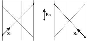
Fig.
8. Scheme of the lashings reaction system exhausts to
the centrifugal force on the curve of the road
Fig.
8 shows that at the time
of driving on a curve road, centrifugal force Foz
influences the 3’ and 4’ lashing rods.
To determine the centrifugal force, the most disadvantageous road conditions
are assumed. The calculation assumes that the load can travel at maximum speed
v=80 km/h=22.2 m/s. This speed applies to motorways, expressways and 2-lane
roads outside the built-up areas of Poland. For roads
having the minimum speed curve radiuses are R=250 m. By substituting
these values for the dependence (7), the centrifugal force at the level Foz=35 520
N is obtained. On the other hand, considering the European standard and other
adverse road conditions related to sudden lane change such as avoiding an
obstacle, the centrifugal force is:
![]() (8)
(8)
Taking
into account the frictional force of FT, the final centrifugal force
Foz acting on the considered load is:
![]() (9)
(9)
The
determined values of forces acting on the conveyor drive system on a container
platform are presented in Table 2.
Tab.
2
Values of forces acting on a conveyor drive system packed on a container
platform
|
Direction
of force |
Force
value |
|
In the direction of the longitudinal movement,
at the moment of braking |
|
|
In the direction of the opposite longitudinal
movement at the moment of starting |
|
|
In the transverse direction when driving on
the arc of the road |
|
|
Vertical direction when driving on uneven
roads |
|
Sensors
of vectors of the reaction forces in lashings no. 1, 1’, 2, 2’, 3,
3’, 4 and 4’ are opposed to the return forces during transport
loads on the platform of the container. The inertia
force Foz is directed
forward and its effect is transferred to the cross-lashings no. 4, 4’ and
longitudinal lashings no. 2, 2’. Foz centrifugal force acts transversely to the direction
of travel, and its operation is transferred to the cross lashings no. 3 and 4. When
Foz centrifugal force changes, the reactions will occur in 3’
and 4’ lashings. Tilt angles of lashings are required to determine the
reaction forces. Fig. 9 shows the angles β1,
β2, describing the arrangement of cargo lashing in
the Oxz plane at reaction point C.
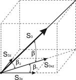
Fig.
9. Angles of lashing no. 3 alignment at the C3’ attachment
point
Reactions
considered at points C and C’ are the condition
of the load when the transported load on the container platform is affected by
the forward inertia force FaxH as
a result of the vehicle braking. The reactions at points C and C’ have
the same values (S3x=S3’x) since
the fixing lashing are arranged symmetrically. Strength
S3 was
decomposed into components acting in directions Ox,
Oz.
![]() (10)
(10)
![]() (11)
(11)
Similarly,
the S1 force in the direction of Ox and Oz was decomposed
into the force of the reaction of lashings 1 and 2 at points C1 and
C2.
![]() (12)
(12)
![]() (13)
(13)
The
S3x, S3x’ and S1x, S1x’
reaction forces maintain the charge in equilibrium when the inertial force at
the moment of braking FaxH is acting in the longitudinal direction.
The load remains in balance if:
![]() (14)
(14)
When S1=S1’,
S3=S3’, then the equation takes the following form:
![]() (15)
(15)
After
substituting the relations defined in equation (10) and (12) into equation
(15), we obtain:
![]() (16)
(16)
Equation
(16) presents the state of equilibrium at the moment the vehicle brakes. To
determine the forces in the S3 and
S1 lashings, tensile forces in lashings 3 and 4
arising from the centrifugal force at the moment of the arc or other lane
change manoeuvre must be determined.
When
driving on the arc of the road, lashings 3 and 4 are tensed under the influence
of the centrifugal force Foz, based on the dependence:
![]() (17)
(17)
After substituting dependence (11) and
assuming that S3z=S4z due to the symmetry of the attached
load, the equation (17) takes the following form:
![]() (18)
(18)
After transforming the equation (18) to S3,
we obtain the equation of the force in fixing lashing 3 and simultaneously in
lashing 4.
![]() =52 083.3
N (19)
=52 083.3
N (19)
It is clear from the calculation that the fixing lashings 3
and 4 have a tensile strength of 52,083.3 N. It follows that the forces acting
on the lashings of cross attachment S3,3’=52 083.3 N. If
the load acting on the 3 and 4 lashings is known, the force that tenses the 1
and 1’ lashings can be determined. Due to the symmetry, only S1 may be
calculated. After substituting the force S3 for the equation and the corresponding
transformation, we obtain the force S1,1’=20 290.85 N.
The analysis shows that for
the conveyor drive system transported on the container in the individual
attachment lashings force values appear as presented in Table 3.
Following the analysis,
associated with the forces, selection of appropriate fixing equipment should be
done according to lashing capacity (LC).
Tab.
3
Size of forces calculated on
individual lashings securing conveyor drive system
|
No.
of fixing lashing |
Determination
of tensile force of fixing cable |
Value
of maximum forces in tension [N] |
|
1 |
S1 |
20 291 |
|
1’ |
S1’ |
|
|
2 |
S2 |
|
|
2’ |
S2’ |
|
|
3 |
S3 |
52 083 |
|
3’ |
S3’ |
|
|
4 |
S4 |
|
|
4’ |
S4’ |
|
|
5 |
S5 |
22
500 |
|
5’ |
S5’ |
3.5. Selection of lashings securing transported cargo
To
secure the conveyor on a container, according to the guidelines contained in
the standard, the following fixing lashings should be applied: S1,
S1’ and S2, S2’, lashings
should have a tensile strength of S1,2 =20 291 N,
lashings S3, S3’ and
S4, S4’ should have a tensile strength of
S3,4=52 083 N and lashing S5=22 500
N.
Lashing
straps recommended by the carrier was selected for conveyor attachment. Lashing
straps usually consist of artificial fibres (usually polyester according to EN
12195-2). Each tape harness is labelled with the appropriate information, shown
in Fig. 10, which is lashing capacity (LC) in decaNewtons (daN-
official force unit corresponding to 1 kg), standard tension force (STF) which is obtained when the manual force is applied to the
tensioner (SHF) [3, 19].
|
Breaking
force 4000
kg |
|
LC
1600 daN |
|
SHF
50 daN / STF 400 daN |
|
100%
POLYESTER |
|
LGL
10 m |
|
!
NOT FOR LIFTING ! |
|
IRU
CIT |
|
VAT No. XXXYYY-YYYY |
|
2017 |
|
EN 12195-2 |
Fig.
10. Cargo lashing belt label according to the EN 12195-2 standard
Fixing equipment
in the form of fastening belts should be made following the EN 12195-2
standard. Companies that manufacture these types of fastening belts have the
straps in their assortments in the following ranges:
− lashing
strap width from 25 to 75 mm,
− lashing strap
maximum load from 250 to
10 000 daN,
− safety factor of the
securing straps is 2.
When
attaching an 18t load on conveyor drive system, the following fastening belts
should be used [12]:
a.
for lashings: S1, S1’ and S2, S2’
one-piece belt with manual tensioner was used (Fig. 11)
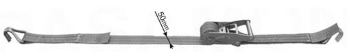
Fig.
11. Fastening strap used for lashings S1, S1’
and S2, S2’
This
type of lashing strap has the following parameters and implementations used
(Table 4):
− strap width 50 mm,
− lashing capacity LC=2
000 daN.
Tab.
4
Fastening
strap types used for lashings S1, S1’
and S2, S2’ of conveyor securing
|
LC
- lashing capacity |
Implementation possibilities |
||
|
2000 [daN] |
4000 [daN] |
4000 [daN] |
|
|
|
|
|
Two-piece with profile hooks |
|
Two-piece with U-type hooks |
|||
|
Two-piece with carabiners hooks |
|||
|
One-piece with a closed circuit |
|||
b.
for lashings: S3, S3’
and S4, S4’, the following fastening straps
were used (Fig. 12):
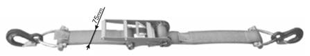
Fig.
12. Fastening strap used for lashings S3, S3’ and
S4, S4’
This
type of lashing strap has the following parameters and implementations used
(Table 5):
− strap width 75 mm,
− lashing capacity LC=5
000 daN.
Tab.
5
Fastening
strap types used for lashings S3, S3’
and S4, S4’ of conveyor
securing
|
LC
- lashing capacity |
Implementation possibilities |
||
|
5000 [daN] |
10000 [daN] |
10000 [daN] |
|
|
|
|
|
Two-piece with forged security hooks |
|
Two-piece with profile hooks |
|||
|
One-piece with a closed circuit |
|||
c.
for lashings: S5 and S5’
fastening straps of the following parameters should be used (Fig. 13): strap width - 50 mm, lashing
capacity LC=2 500 daN with different types shown in Table 6.
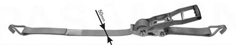
Fig.
13. Fastening strap used for lashings S5
and S5’
Tab.
6
Fastening
strap types used for lashings S5 and S5’
of conveyor securing
|
LC
- lashing capacity |
Implementation possibilities |
||
|
2500 [daN] |
5000 [daN] |
5000 [daN] |
|
|
|
|
|
Two-piece with profile hooks |
|
Two-piece with U-type hooks |
|||
|
Two-piece with carabiners hooks |
|||
|
One-piece with a closed circuit |
|||
For
load safety, the use of a similar procedure for choosing the form of security
and fixing means selection is recommended, analysing each case separately at
the planning stage of the transport process according to standardisation [1, 3,
19].
4.
CONCLUSIONS
This article
is focused on
intermodal transportation of mining components packed in containers or other
cargo transport units together with the problem of its proper securing. Using
appropriate equipment, method of cargo securing and correct transport unit are
very important elements among the six key factors mentioned as most important
of proper and safe transportation planning. The decision of packaging and
fixing means selection, however, depends on the forces acting on the load. EN
12195-1 standard is usually used for calculation of securing forces which
contains the European Commission guidelines on cargo security. However, many
carriers use the VDI2700 German standard where the basic forces acting on the
cargo, practical way of proper location and installing the fastening devices
are explained. Furthermore, this
article presents a case study of container packing and securing of a mining
conveyor, which was sent from Poland to Indonesia. First, the strap cross fixing method was determined with five
lashings. Thereafter, considering the friction forces of the load and the
lashing pressing forces, final inertial force (FaxH=104 948 N)
while vehicle braking was calculated. It should be
secured with lashing equipment no. 3, 3’ and 1, 1’. While driving
on a curve road, centrifugal force (Foz=53 684 N) influences the 3’ and 4’ lashing rods.
Then, forces acting on the lashings of
cross attachment S3,3’=52 083.3 N were
determined and are the same for lashings 4 and 4’. Basing on this
knowledge, lashing strap of 75 mm width and lashing capacity LC=5 000 daN
was selected for cargo securing. Similarly, forces acting on lashings 1,
1’ and 2, 2’ were determined (S1,1’=20 291 N)
and appropriate strap of 50 mm width and 2 000 daN lashing capacity was
proposed. For lashings 5 and 5’ (S5,5’=22 500 N),
strap with 50 mm width and LC=2 500 daN lashing capacity is proposed. Finally,
various types of usable selected belts with different hook variants were
presented.
References
1.
European Best Practice Guidelines on Cargo
Securing for Road Transport. 2014. European Commission, Directorate-General for
Energy and Transport,
ISBN: 978-92-79-43665-9. DOI: 10.2832/80373.
2.
Grunau Peter. 2015. Cargo Handling and Stowage: A Guide for Loading, Handling, Stowage,
Securing, and Transportation of Different Types of Cargoes, Except Liquid
Cargoes and Gas. BoD–Books on Demand. ISBN: 9783739217574.
3.
IMO/ILO/UN ECE Guidelines for Packing of Cargo Transport Units (CTUs)
(International Maritime Organization. London. 1997. ISBN: 92-801-1443-3).
4.
Jagelcak Juraj, Jozef Gnap. 2011. Different
measures for load securing create barriers in international road freight
transport. Archives of Transport System Telematics. 4(2): 10-17. ISSN:
1899-8208.
5.
Jagelcak Juraj. 2007. „Equation of the Standard EN 12195-1 Stipulates
Unreasonable Demands for Cargo Securing”. Communications – Scientific Letters of the University of Zilina
(Komunikacie) 9(4): 30-33. ISSN: 1335-4205.
6.
Jagelcak Juraj. 2015. Loading and fastening of freight in road transport. 2nd edition.
ISBN: 978-80-554-1083-8.
7.
Jia Junbo. 2007. „Investigations of vehicle securing without lashings
for Ro-Ro ships”. Journal of marine
science and technology 12(1): 43-57.
DOI 10.1007/s00773-006-0240-7.
8.
Mao Li, Runtian Jing. 2009. „Simulation Analysis for Cargo
Mechanical State during Transportation”. In: Logistics: The Emerging Frontiers of Transportation and Development in
China. Edited by Rongfang (Rachel) Liu, Jin Zhang, Changqian Guan. P. 821-827.
DOI: https://doi.org/10.1061/9780784409961.
9.
Nieoczyma Aleksander, Jacek Cabanb, Jan Vrabelc.
2019. „The
problem of proper cargo securing in road transport – case study”. Transportation Research Procedia 40:
1510-1517. DOI: https://doi.org/10.1016/j.trpro.2019.07.209.
10.
Polzin Steven E. 2011. Security considerations in transportation planning: A white paper. P.
12-36. Luxembourg: Publications Office of the European Union.
ISBN: 978-92-79-18270-9. DOI: 10.2832/30955.
11.
Rievaj Vladimir, Ján Vrabel,
František Synak, Ladislav Bartuska. 2018. „The Effects of vehicle load on driving
characteristics”. Advances in
science and technology – research journal 12(1): 142-149. DOI:
10.12913/22998624/80896.
12.
Safe
Packing of Cargo Transport Units (CTUs) –
COURSE, Model course 3.18. International Maritime Organization. London. 2001.
ISBN: 92-801-5116-9.
13.
Saruchera Fanny. 2020. “Determinants of
effective high-risk cargo logistics at sea ports: A case study”. Journal of Transport and Supply Chain
Management 14: a488. DOI: https://doi.org/10.4102/jtscm.v14i0.488.
14.
Sidney W.A. Dekker.
2004. Ten questions about human error: A
new view of human factors and system safety. Human
Factors in Transportation Series. London. CRC Press. ISBN: 0805847456.
15.
Singh Paul, Jay Singh, John Antle, Erin Topper.
2014. ”Load Securement and Packaging Methods to Reduce Risk of Damage and
Personal Injury for Cargo Freight in Truck, Container and Intermodal
Shipments”. Journal of Applied Packaging Research 6(1): Article 6.
DOI: 10.14448/japr.01.0005.
16.
Shtykov Victor Pavlovich. 2014. ”The
carrier's liability for failure to vehicles to transport cargo”. Life Science Journal 11(9): 292-294.
17.
Stajniak Maciej, Adam Koliński. 2016.
”The impact of transport processes standardization on supply chain
efficiency”. LogForum 12(1): 37-46. DOI: 10.17270/J.LOG.2016.1.4.
18.
Stapleton Drew M., Vivek Pande, Dennis O'Brien.
2014. ”EXW, FOB or FCA? Choosing the right Incoterm and why it matters to
maritime shippers”. Journal
of Transportation Law, Logistics, and Policy 81(3): 227-248. ISSN:
1078-5906.
19.
STN EN 12195-1:2011. Load restraint assemblies on road vehicles – Safety – Part 1: Calculation of
securing forces.
20.
Stokłosa
Józef, Grzegorz Koszałka, Leszek Gil. 2012. ”Analiza sił
w elementach mocujących ładunki na pojazdach samochodowych”. Postępy Nauki i Techniki
12:
94-100. [In English: “Analysis of forces in elements used for fastening
loads on road vehicles”].
21.
Strauch Barry. 2017. Investigating human error: Incidents, accidents, and complex systems.
London. CRC Press. ISBN: 978-1-4724-5868-1.
22.
Vlkovský Martin, Teodora Ivanuša,
Vlastimil Neumann, Pavel Foltin, Hanna Vlachová. 2017.
”Optimizating cargo security during transport using dataloggers”. Journal of Transportation Security 10:
63-71. Springer Science+Business Media. DOI: 10.1007/s12198-017-0179-4.
23.
Vlkovsky Martin, Katerina Pochobradska, Pavel
Foltin, Vaclav Zajicek. 2016. ”The cargo securing based on European
standards and its applicability in off-road transport conditions”. 3rd International Conference on Traffic
and Transport Engineering (ICTTE). 24-25 November 2016: 603-607. Belgrade,
Serbia: Scientific research center LDT Belgrade. ISBN: 978-86-916153-3-8.
24.
Zong Cheng-Giang, Zhang Hong-Wei, Huang Chao-Zhi,
Dong Jin-Song. 2017. ”Research on the influence of cargo securing force
with typical road alignments and vehicle working conditions”. 4th International Conference on
Transportation Information and Safety (ICTIS): 27-32. Banff, AB. DOI: 10.1109/ICTIS.2017.8047737.
Received 03.08.2020; accepted in revised form 20.10.2020
![]()
Scientific
Journal of Silesian University of Technology. Series Transport is licensed
under a Creative Commons Attribution 4.0 International License