Article
citation information:
Pashayev, A., Sabziev, E. Refinement of the parameters of a
mathematical model of quadcopter dynamics. Scientific
Journal of Silesian University of Technology. Series Transport. 2020, 109, 141-151. ISSN: 0209-3324. DOI: https://doi.org/10.20858/sjsutst.2020.109.13.
Adalat PASHAYEV[1],
Elkhan SABZIEV[2]
REFINEMENT
OF THE PARAMETERS OF A MATHEMATICAL MODEL OF QUADCOPTER DYNAMICS
Summary. Errors in the
calculation of the parameters of quadcopter control models at design stage
significantly change the desired aerodynamic properties of the drone and make
it difficult to control its flight along the intended path. Therefore, to
calculate the adequate operation modes of the blades, it becomes necessary to
refine some parameters of the mathematical model of the drone as accurately as
possible. This paper shows the possibility of using control parameters
(rotational speed of the blades) and information received from navigation
devices of the drone to refine the values of the parameters of the mathematical
model of the drone. For this purpose, a mathematical model of a quadcopter
is built, and the problem of refining the parameters of its dynamic model
is investigated based on the information received from navigation devices and
the control parameters in the initial period of its flight. From the results
obtained from several consecutive measurements, a system of equations
expressing a mathematical model is solved. The mean value of the corresponding
solutions of the system of three-dimensional linear equations obtained at
different time intervals is the refined value of the parameters.
Keywords: mathematical model, identification, moment of
inertia, windage, quadrocopter
1. INTRODUCTION
The low cost
of unmanned aerial vehicles (drones) has given impetus to their widespread use
for military purposes. The possibility of equipping them with appropriate
hardware makes it possible for them to perform various tasks. Quadcopters
should be mentioned among such currently widely used vehicles. As a rule,
quadcopters are equipped with navigation devices (gyroscope, accelerometer,
etc.), which allow obtaining information related to the drone’s location
and aerial orientation and control its flight.
Dynamic
mathematical models describe the control and movement of the quadcopter. In
this study, the drone is considered as a solid, and its mathematical model
expresses the relationship between the thrust generated by the motor and
acceleration, air drag, torque, rotational speed and velocity of the drone
relative to the earth. There is a wide range of studies dealing with the
dynamic modelling of drones. For instance, [1] is devoted to the building of a
mathematical model of a drone to solve the problem of eliminating its deviation
from the intended flight path. In [2], a mathematical model was built to
control the stability and flight path of a quadcopter. In the paper, feedback
data related to the orientation of the drone is given in the form of Euler
angles. In the mathematical model built in [3], the aerodynamic forces acting
on the drone are not considered, and the case of its flight at low speeds was
studied. In [4], a mathematical model that defines the spatial position of the
quadcopter by Euler angles was developed and used to create a flight simulation
program. In [5], a mathematical model was developed, the quadcopter’s
spatial position being expressed by Euler angles, and a controller stabilising
the altitude and orientation of the drone was developed based on this model.
Several
currently designed drone models provide for the use of MPU-9250 type devices
[6]. Since this device does not measure Euler angles, it is impossible to
directly apply the results of the above studies to solving problems of
quadcopter control when using it. Thus, the accelerometer and gyroscope of
MPU-9250 allow calculating the loads that occur during movement, as well as the
rate of change of Krylov rotation angles (roll, pitch and yaw) [7, P.9], which
determine the spatial position of the drone, and current orientation angles by
integrating these speeds.
A mathematical
model of the quadcopter control problem is built in this paper based on
feedback data received from an MPU-9250 type device. The rotational speeds of
the quadcopter blades are used as control parameters. It is assumed that:
·
the drone has 4 symmetrically fixed identical
motors that rotate its blades;
·
for clarity, if we indicate the drone motors as
shown in Fig. 1, blades 1 and 3 rotate clockwise, and blades 2 and 4
counterclockwise;
·
due to the small angular rotational velocities,
the gyroscopic forces created by the movement of the drone can be neglected;
·
gravity and aerodynamic drag affect the centre
of mass of the drone, so these forces do not create a torque;
·
the mass of the drone is distributed only along
its arms, in other words, the drone's rotary inertia matrix has a diagonal
shape.
The dynamic
model of a quadcopter is expressed by numerous parameters. These parameters are
usually calculated using empirical formulas at the drone design stage. Stable
drone control requires these parameters to be known as accurately as possible.
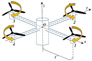
Fig. 1. Quadcopter schematic
Therefore, this paper explores the possibility
of using the control parameters (rotational speed of the blades) and the data
obtained from navigation devices of the drone to refine the values of the
parameters of the mathematical model of the drone.
2.
MATHEMATICAL MODEL OF THE DRONE
To determine the position of the
quadcopter relative to the ground and build a dynamic model, a
fixed-in-the-earth right-handed normal ![]() coordinate system is used.
For clarity, it is assumed that the
coordinate system is used.
For clarity, it is assumed that the ![]() axis is directed vertically upward
in the considered point, and the
axis is directed vertically upward
in the considered point, and the ![]() and
and ![]() axes are directed so that the
axes are directed so that the ![]() plane is perpendicular to
plane is perpendicular to ![]() , forming a right-handed coordinate system.
, forming a right-handed coordinate system.
We
denote by ![]() ,
, ![]() ,
, ![]() the quadcopter’s current
coordinates relative to the
the quadcopter’s current
coordinates relative to the ![]() system at the considered instant
system at the considered instant ![]() , and the components of the velocity vector
by
, and the components of the velocity vector
by ![]() ,
, ![]() ,
, ![]() . It
is obvious that,
. It
is obvious that,
 (1)
(1)
The mathematical model of drone
control provides for setting such a relationship between the flight path ![]() expressed by the coordinates in the
expressed by the coordinates in the ![]() system and the angular rotational
velocities of the blades
system and the angular rotational
velocities of the blades ![]() that
the following two problems can be solved:
that
the following two problems can be solved:
·
the
calculation of the drone’s flight path ![]() according to the angular rotational
velocities
according to the angular rotational
velocities ![]() ;
;
·
the
calculation of the angular rotational velocities ![]() for the execution of the given flight
path
for the execution of the given flight
path ![]() .
.
To specify the physical (inertial)
characteristics of the quadcopter, we introduce a rectangular right-handed ![]() coordinate system fixed to it [7, P.23].
The quadcopter can be described schematically as shown in Fig. 1. Suppose that
the origin of coordinates is located in the centre of the drone, the
coordinate system fixed to it [7, P.23].
The quadcopter can be described schematically as shown in Fig. 1. Suppose that
the origin of coordinates is located in the centre of the drone, the ![]() and
and ![]() axes are directed along its
“arms”, and the
axes are directed along its
“arms”, and the ![]() axis is directed upward perpendicular to
the
axis is directed upward perpendicular to
the ![]() plane.
plane.
As mentioned above, when designing a drone
control system, MPU-9250 type devices are used to provide feedback [6]. These
devices allow expressing the spatial position (orientation) of the drone by the
yaw angle ![]() , the pitch angle
, the pitch angle ![]() , the roll angle
, the roll angle ![]() . The definition of yaw, pitch and
roll angles is given in [7, P.9]. These angles virtually indicate the spatial
position of the
. The definition of yaw, pitch and
roll angles is given in [7, P.9]. These angles virtually indicate the spatial
position of the ![]() coordinate system fixed to the drone
relative to the normal
coordinate system fixed to the drone
relative to the normal ![]() coordinate system. Matrix (2) can be used
to find in the
coordinate system. Matrix (2) can be used
to find in the ![]() coordinate system the components of the
vector given in the fixed-in-the-earth
coordinate system the components of the
vector given in the fixed-in-the-earth ![]() coordinate system. For simplicity, for
the angle
coordinate system. For simplicity, for
the angle ![]() under consideration,
under consideration, ![]() and
and ![]() are written instead of
are written instead of ![]() and
and ![]() from here next.
from here next.
 . (2)
. (2)
To build the drone control model, we write
the equations of its movement relative to the ![]() coordinate system [9, P.128]:
coordinate system [9, P.128]:
![]() , (3)
, (3)
![]() , (4)
, (4)
where ![]() is the mass of the drone,
is the mass of the drone, ![]() is the rotary inertia matrix,
is the rotary inertia matrix, ![]() is the velocity of the drone,
is the velocity of the drone, ![]() is the angular rotational velocity of the
drone,
is the angular rotational velocity of the
drone, ![]() is the sum of the forces acting on the
drone,
is the sum of the forces acting on the
drone, ![]() is the moment created by the forces
acting on the drone. Equation (3) expresses the balance of forces, and equation
(4) expresses the balance of moments. The relationship between the velocities
is the moment created by the forces
acting on the drone. Equation (3) expresses the balance of forces, and equation
(4) expresses the balance of moments. The relationship between the velocities ![]() and
and ![]() is determined by the following equality:
is determined by the following equality:
![]() . (5)
. (5)
The position of the drone relative
to the ![]() coordinate system can be identified with
the position of the
coordinate system can be identified with
the position of the ![]() coordinate system relative to
coordinate system relative to ![]() . Taking
this into account, the angular velocity
. Taking
this into account, the angular velocity ![]() and the angular acceleration
and the angular acceleration ![]() of the drone relative to
of the drone relative to ![]() can be calculated as follows:
can be calculated as follows:
 ,
,  . (6)
. (6)
Let us give the procedure of
calculation of the vectors ![]() and
and ![]() on the right-hand side of the system of
equations (3)-(4).
on the right-hand side of the system of
equations (3)-(4).
Following the above conditions for
the direction of rotation of the drone’s blades, the propelling force
created by its motors is always oriented in the direction of the ![]() axis of the fixed
axis of the fixed ![]() coordinate system:
coordinate system:
 , (7)
, (7)
where ![]() is a coefficient determined
experimentally,
is a coefficient determined
experimentally, ![]() is the rotational speed of the blades of
the
is the rotational speed of the blades of
the ![]() -th
motor. Here and thereafter, the asterisk indicates the transposition operation.
-th
motor. Here and thereafter, the asterisk indicates the transposition operation.
The aerodynamic drag is directed
opposite to the movement of the drone:
![]() , (8)
, (8)
where ![]() is the drag coefficient, which is
proportional to the area of the projected plane perpendicular to the direction
of the drone’s movement and depends on its aerodynamic shape. In the
general case, the relationship between the coefficient
is the drag coefficient, which is
proportional to the area of the projected plane perpendicular to the direction
of the drone’s movement and depends on its aerodynamic shape. In the
general case, the relationship between the coefficient ![]() and the aerodynamic shape is very complex
and depending on the direction of movement for the drone under consideration,
its value can be determined experimentally [10]. Usually, for simplicity, this
coefficient is assumed to be identical in all directions. Therefore, the force
and the aerodynamic shape is very complex
and depending on the direction of movement for the drone under consideration,
its value can be determined experimentally [10]. Usually, for simplicity, this
coefficient is assumed to be identical in all directions. Therefore, the force ![]() can be broken into the following
components:
can be broken into the following
components:
![]() . (9)
. (9)
Regardless of the spatial position,
gravity acting on the drone is always directed vertically to the earth. Using
the transformation matrix (1), we can obtain the following formula for
expressing gravity relative to the ![]() coordinate system:
coordinate system:
![]() . (10)
. (10)
As mentioned above, it is assumed
that gravity and aerodynamic drag affect the centre of mass of the drone, so
these forces do not create a torque. Since the drone's motors are fixed to it,
the torque generated by the rotation of the blades can be expressed in the ![]() coordinate system as follows:
coordinate system as follows:
 , (11)
where ![]() is the length of the arms of the drone,
and
is the length of the arms of the drone,
and ![]() is a coefficient determined
experimentally.
is a coefficient determined
experimentally.
Also, according to the condition that the
drone rotary inertia matrix has a diagonal shape, it can be written as the
following diagonal matrix:
 . (12)
According to equality (6)
 (13)
(13)
If we write the values in equations
(3)-(4) in terms of components, we can obtain the following system of
differential equations for the dynamic model of the drone:
 (14)
(14)
 (15)
(15)
Based on equations (4), we can
write equations expressing the components of the drone’s velocity vector
relative to the earth:
 (16)
(16)
To solve system (1), (6)-(16) by
the functions ![]() ,
, ![]() , their initial values for a certain moment
, their initial values for a certain moment ![]() must be given:
must be given:
 (17)
(17)
 (18)
(18)
 (19)
(19)
 (20)
(20)
System (1), (6)-(20), being a
Cauchy problem written for a system of ordinary differential equations,
expresses the dynamic model of a drone.
3. STATEMENT OF THE PROBLEM OF PARAMETER REFINEMENT (IDENTIFICATION)
Depending on the tasks
performed, devices connected to the quadcopter (photo and video camera, radio
repeater, packages of various shapes, etc.) can to some extent change their
aerodynamic and technical characteristics. In this regard, the values of some
parameters of the mathematical model of a quadcopter can differ from the
calculated indicators.
The dynamic model of a
quadcopter is expressed by several parameters, including the total mass of the
drone, the components of the moment of inertia, the coefficient of
proportionality between the rotational speed of the blades and the lifting
force that they create, and other quantities. These values, in turn, depend on
the size of the drone, the mass of its parts, the distribution of these parts
relative to the centre of gravity and other factors. They can be determined
experimentally or calculated analytically in the framework of hypotheses put
forward in building the mathematical model. However, the errors in finding
these parameters significantly change the aerodynamic properties of the drone,
which makes it difficult to control its flight along the intended path.
The change in aerodynamic
properties is reflected in the fact that the rotation of the blades in design
modes is not enough for the drone to move along the intended path, and these
modes need to be altered. In essence, it is necessary to refine some parameters
of the mathematical model of the drone as accurately as possible to calculate
adequate modes of operation of the blades. Mathematically, this is considered
an inverse problem. Thus, the possibility of using the control parameters
(rotational speed of the blades) and the data from navigation devices of the
drone to refine the values of the parameters of the mathematical model of the
drone is investigated in the following paragraphs.
An analysis of the dynamic
model of a quadcopter written in the form of system (1), (6)-(20) above shows
that the quantities in the model are divided into three groups.
The first group includes
control parameters ![]() adjusted by the operator controlling the drone.
adjusted by the operator controlling the drone.
The second group includes the
quantities calculated based on the loads ![]() measured by navigation devices and the
derivatives of Krylov orientation angles
measured by navigation devices and the
derivatives of Krylov orientation angles ![]() . The application of the operations
. The application of the operations ![]() ,
, ![]() ,
, ![]() ,
, ![]() ,
, ![]() ,
, ![]() ,
, ![]() ,
, ![]() ,
, ![]() ,
, ![]() ,
, ![]() ,
, ![]() ,
, ![]() ,
, ![]() ,
, ![]() allows calculating all the other
quantities included in the mathematical model.
allows calculating all the other
quantities included in the mathematical model.
The third group includes
the quantities ![]() , which describe the physical and technical
characteristics of the quadcopter and are considered unchangeable (constant)
throughout the flight. Note the following two considerations concerning these
variables.
, which describe the physical and technical
characteristics of the quadcopter and are considered unchangeable (constant)
throughout the flight. Note the following two considerations concerning these
variables.
I. Since the asymmetric
design of the quadcopter substantially disrupts the stability of its flight,
serious attention is paid to this issue, and from this point of view, we can
assume with great accuracy that ![]() .
.
II. Equations (8) that
determine the quadcopter’s orientation are invariant concerning the
relations ![]() and
and ![]() .
.
With these
considerations in mind, refining the values of the parameters of the dynamic
model of a quadcopter implies finding the quantities ![]()
![]() with sufficient accuracy. The initial
approximate values of these quantities are assumed to be known and to solve the
problem of parameter refinement, one can conduct flight experiments, adjusting
the control parameters, and use measurements of navigation devices.
with sufficient accuracy. The initial
approximate values of these quantities are assumed to be known and to solve the
problem of parameter refinement, one can conduct flight experiments, adjusting
the control parameters, and use measurements of navigation devices.
4. SOLUTION OF THE PROBLEM
Data coming from navigation
devices is calculated at discrete instants in time, and the controller
processor spends a certain amount of time on these calculations. In this
regard, in the practical solution of the theoretical continuous mathematical
model from the previous sections, a discrete analogue must be written.
Data received from
navigation devices can be attributed with sufficiently high accuracy to the
same time instants ![]() , where
, where ![]() is a time discrete, a known quantity,
is a time discrete, a known quantity, ![]() . To calculate the refined value of the
constants in the mathematical model, we can consider the time instants
. To calculate the refined value of the
constants in the mathematical model, we can consider the time instants ![]() , which differ from each other by the control
parameters of the identical flight, where
, which differ from each other by the control
parameters of the identical flight, where ![]() is a natural number.
is a natural number.
First, let us give the
calculation procedure for the quantities ![]() . If we group system (14) according to the
sought-for quantities and replace the coefficients with finite differences for
each considered
. If we group system (14) according to the
sought-for quantities and replace the coefficients with finite differences for
each considered ![]() , we get:
, we get:
 (21)
(21)
For each time instant ![]()
 (22)
(22)
where
![]() ,
, ![]() ,
, ![]() ,
, ![]() ,
, ![]() ,
, ![]() ,
,  ,
, ![]() ,
, ![]() ,
, ![]() .
.
The index ![]() below indicates that the
bracketed expression should be written as finite differences at the considered
point
below indicates that the
bracketed expression should be written as finite differences at the considered
point ![]() . It should be noted that due to errors in
the measurements of the navigation devices, system (22) can degenerate at some
values of
. It should be noted that due to errors in
the measurements of the navigation devices, system (22) can degenerate at some
values of ![]() . Except in cases of degeneracy, the mean
value of the solutions found for different
. Except in cases of degeneracy, the mean
value of the solutions found for different ![]() can be taken as the refined
value of the quantities
can be taken as the refined
value of the quantities ![]() .
.
Further, we consider the
problem of calculating the relations ![]() and
and ![]() using the found coefficient
using the found coefficient ![]() . If we express the second-order derivatives
of orientation angles in equations (15) by the quantities
. If we express the second-order derivatives
of orientation angles in equations (15) by the quantities ![]() and rewrite them for the relations
and rewrite them for the relations ![]() , we obtain:
, we obtain:
 (23)
(23)
or for every moment ![]() :
:
 (24)
(24)
where
![]() ,
, ![]() ,
, ![]() ,
,
![]() ,
,
![]() ,
,
![]() ,
,
![]() ,
,
![]() .
.
It should also be noted
that due to errors in the measurements of navigation devices, system (24) can
degenerate for some values of ![]() . Except in cases of degeneracy, the mean
value of the solutions found for different
. Except in cases of degeneracy, the mean
value of the solutions found for different ![]() can be taken as the refined
value of the relations
can be taken as the refined
value of the relations ![]() and
and ![]() .
.
5. CONCLUSION
The
dynamic model of a quadcopter is built in this paper, using the rotational
speeds of the blades of the quadcopter motors, which are the control
parameters, the loads measured by the accelerometer and the Krylov angles (yaw,
pitch and roll angles) measured by the gyroscopes, which are the feedback data.
The group of invariant quantities that are part of the mathematical model of
the drone defining the dynamics of its movement is determined, and the
possibility of determining their values as a result of flight experiments is
substantiated.
References
1.
Hoffmann Gabriel M.,
Haomiao Huang, Steven L. Waslander, Claire J. Tomlin. "Quadrotor
Helicopter
Flight Dynamics and Control: Theory and Experiment". AIAA Guidance, Navigation and Control Conference and
Exhibit.
20-23 August 2007, Hilton Head, South Carolina. 20 P.
2.
Teppo
Luukkonen. "Modelling and Control of
Quadcopter". School of Science, Espoo. August 22, 2011. P. 26.
3.
Marcelo De Lellis
Costa de Oliveira. "Modeling, Identification and
Control of a Quadrotor Aircraft" Czech Technical
University in Prague. Master’s Thesis.
Prague. June 2011. 75 P.
4.
Гурьянов
А.Е. 2014. "Моделирование
управления
квадрокоптером". Инженерный
вестник 8: 523-534. [In Russian: Guryanov
A.Y. 2014. "Quadcopter control modeling". Inzhenerniy Vestnik
8: 522-534].
5.
Гэн К., Н.А.
Чулин. "Алгоритмы
стаблизации
для
автоматического
управления
траекторным
движением
квадрокоптера". 2015. Наука и
Образование.
МГТУ
им.Н.Э.Баумана.
Электронный
журнал. 5: 218-235. [In Russian: Gen K., N.A. Chulin. 2015. "Stabilization algorithms for automatic control of the quadcopter
trajectory movement". Nauka i Obrazovaniye. N.E. Bauman MSTU. Electronic
journal 5: 218-235].
6.
MPU-9250 Nine-Axis (Gyro + Accelerometer + Compass)
MEMS MotionTracking™ Device. Available at: https://invensense.tdk.com/products/motion-tracking/9-axis/mpu-9250/.
7.
Ефимов
В.В. "Основы
авиации.
Часть I. Основы
аэродинамики
и динамики
полета летательных
аппаратов".
Москва: МГТУ
ГА, 2003. [In Russian: Yefimov V.V. "The basics
of aviation. Part I. Fundamentals of aerodynamics and flight dynamics of
aircraft". Moscow: MSTU GA, 2003].
8.
"Динамика
летательных
аппаратов в
атмосфере.
Термины,
определения
и
обозначения". ГОСТ
20058-80. Москва. 1980. 52 С. [In Russian:
"Dynamics of aerial vehicles in the atmosphere.
Terms, definitions and designations". GOST 20058-80.
Moscow. 1980. 52 P.].
9.
Бухгольц
Н.Н. "Основной
курс
теоретической
механики". Ч.1. М.:
Наука. 1965. 468 С. [In Russian: Buchholz N.N. "The basic course
theoretical mechanics". Part 1. M.: Nauka.
1965. 468 P.].
10.
Бедржицкий Е.Л., Б.С. Дубов, А.Н. Радциг. "Теория и практика аэродинамического эксперимента". М.: МАИ. 1990. 216 с. ISBN:
5-7035-0003-6. [In Russian: Bedrzhitsky E.L., B.S. Dubov, A.N. Radtsig.
"Theory and practice of aerodynamic experiments". M.: MAI. 1990. 216 P. ISBN: 5-7035-0003-6].
Received 11.07.2020; accepted in revised form 28.10.2020
![]()
Scientific
Journal of Silesian University of Technology. Series Transport is licensed
under a Creative Commons Attribution 4.0 International License