Article
citation information:
Mantič, M., Kuľka, J.,
Kopas, M., Faltinová, E., Hrabovský, L. Limit states of steel supporting
structure for bridge cranes. Scientific
Journal of Silesian University of Technology. Series Transport. 2020, 108, 141-158. ISSN: 0209-3324. DOI: https://doi.org/10.20858/sjsutst.2020.108.13.
Martin MANTIČ[1],
Jozef KUĽKA[2],
Melichar KOPAS[3],
Eva FALTINOVÁ[4],
Leopold HRABOVSKÝ[5]
LIMIT
STATES OF STEEL SUPPORTING STRUCTURE FOR
BRIDGE CRANES
Summary. This paper describes a question of evaluation
necessity of bridge cranes using the method of limit deformation state and
oscillation damping. The solution was performed by means of theoretical
analysis and an experimental verification at the selected bridge crane. The
final result sounds that in the case of a correct strength computing of given
bridge crane, it is not necessary to also check deformation and damping of
oscillation as well.
Keywords: oscillation, damping, energy, experiment,
deflection, time
1. INTRODUCTION
The questions concerning
vibrations of the bridge cranes are analysed in many professional works from
various authors. For example, vibrations of the crane girder, which are
occurring as a consequence of the crane travel on the crane track, are
described by the authors in the works [1-3].
Scientific investigation
of crane oscillations, together with the presentation of possibilities on how
to eliminate these oscillations using a suitable form of the crane control
strategy, is presented in [4-7].
Other methods, which are
determined for the elimination of the crane oscillations by optimisation of the
crane control components and mechanisms, are introduced in [8-10].
Different proposals of a
dynamic model relating to the abovementioned problems are given in [11-14] and
the corresponding experimental methods are in
[15, 16].
Another
interesting approach to the investigation of mechanical vibration, damage of
transport machine parts and generation of failures is presented in [17-27].
Other
experimental studies dealing with the mechanical properties of a layered beam,
which is partially treated with a damping element based on a granular
material, offers [28].
The author of [29], is
focused on the assessment of vibration control performance using enhanced smart
constrained layer damping treatment with edge elements. The non-linear dynamics
of a crane is investigated in the contribution [30].
The commonly used or
standard approach to the solution of a damping process represents the
application of the logarithmic decrement, which enables estimation of the
damping ratio from a time history of the oscillation process.
Analysis of this method
and optimisation of the parameters during the processing and evaluation of the
results is presented in [31, 32].
A new algorithm OMI
(Optimization in Multiple Intervals), which is intended for computation of the
logarithmic decrement concerning the exponentially damped harmonic
oscillations, is described as well as compared with the classic computational
methods in the publications [33, 34].
According to these
articles, it is possible to say that the OMI algorithm is proved to be the best
solution in the computation of the logarithmic decrement and the resonant
frequency for high damping levels. Moreover, it is possible to take into
consideration, a typical causal relation between the wear process and wear
damage of constructional parts, which is introduced for example in [35].
The existing STN 27 0103 [36] informs the
design of steel crane structures according to two groups of limit states.
For
the first group of limit states, which lead to the loss of loading capacity or
the loss of position stability, the following criteria are central to the
design of steel supporting structure:
·
strength and stability,
·
fatigue strength,
·
position stability.
For
the second group of limit states, the following criteria are crucial:
·
static deformation (deflection, displacement, and twisting),
·
dynamic structure response (steel structure frequency, amplitude,
and damping).
The second group of limit states is outlined in the Article
X of the standard only in section 66, which states as follows:
“Deformation and oscillation damping must not affect operational safety
and must not interfere with proper crane function with regard to its work
specifications”. In Annex VIII, the standard recommends how to approach
the bridge crane evaluation.
To a great extent, the STN 27 0103 [36]
overlaps with the German DIN standard 15018 “Krane. Grundsätze
für Stahlwerke. Berechnung“ [37]
in the calculation procedures. This DIN, however, does not specify checking for
the limit state of deformation and damping.
This article lays out the theoretical analysis which
consequently ties into the experimental analysis on a particular bridge crane.
2. OSCILLATION
DAMPING OF A STEEL SUPPORTING STRUCTURE IN A BRIDGE CRANE
A degree of freedom in a
flexible system is conceived as a number of independent coordinates which
determine the location of all the system’s masses.
If the continuous
distribution of the flexible elements is small in comparison with the masses
distributed in the individual points, then the flexible element mass (m) can be
downplayed and only the coordinates of the masses distributed in the points
examined.
Let us propose that the
resistance of the surroundings is directly proportional to the speed in the
following relation:
Fresist = – k.v , where k > 0,
(1)
k – the damping
coefficient (kg.s-1).
The resistance force counters the speed which is
expressed by the minus sign in this formulation. If the acting restoring force
is directly proportional to the displacement, the equation of motion is as
follows:
![]() ,
(2)
,
(2)
c – spring stiffness (N.m-1).
Once the substitution is applied:
where b is the damping coefficient and the ω0 constant is the natural
angular frequency, that is, the angular frequency of the undamped harmonic
oscillator.
After the adjustment, we get the following equation of motion:
![]() .
(4)
.
(4)
The solution to the homogenous second order
differential equation points to the following formulation:
x = eλt, ![]() ,
, ![]() .
(5)
.
(5)
After we apply the function to Equation 4, we
get the following characteristic equation:
![]() ,
(6)
,
(6)
with this solution:
![]() .
(7)
.
(7)
The two ![]() values correspond to the general solution
to Equation 4 in the linear combination:
values correspond to the general solution
to Equation 4 in the linear combination:
![]() (8)
(8)
provided that λ1 ≠ λ2.
According to the extent of the damping, the
following scenarios can play out:
Ø
The damping is large and b2 – ![]() > 0, then both solutions of
the characteristic equation
> 0, then both solutions of
the characteristic equation ![]() are real numbers, and x has no
periodical element. Theoretically, in time t
→
are real numbers, and x has no
periodical element. Theoretically, in time t
→![]() the body gets back to the equilibrium position x = 0. If the damping is this large, the motion is called
aperiodic. Oscillation does not occur at all.
the body gets back to the equilibrium position x = 0. If the damping is this large, the motion is called
aperiodic. Oscillation does not occur at all.
Ø
The damping is such that b2 – ![]() = 0. In such a case, mathematics informs the solution to Equation 4 as the
function x = e-bt as well
as the function x = t.e-bt.
The general solution is their linear combination in the following form:
= 0. In such a case, mathematics informs the solution to Equation 4 as the
function x = e-bt as well
as the function x = t.e-bt.
The general solution is their linear combination in the following form:
![]() . (9)
. (9)
This motion is called critical aperiodic motion.
Ø
Damped oscillatory motion
occurs only when damping is small, if b2
– ![]() < 0. Then:
< 0. Then:
![]() where
where ![]() . (10)
. (10)
The general solution to the equation of motion
is expressed as follows:
![]() .
(11)
.
(11)
Along the lines of this procedure similar to the
harmonic oscillator case, substitution and adjustment bring forward the real
formulation of the general solution:
![]() .
(12)
.
(12)
The angular frequency ![]() is
smaller than the angular frequency at the undamped oscillation of the same
system, and the amplitude which also changes, exponentially decays away over
time:
is
smaller than the angular frequency at the undamped oscillation of the same
system, and the amplitude which also changes, exponentially decays away over
time:
![]() .
(13)
.
(13)
Damped oscillatory motion cannot be considered
periodic because the oscillating point does not reach its original
displacement. The motion here is quasiperiodic, and the T period can only be
conceived as a time interval, past which a mass point passes the equilibrium
position.
The damped oscillation period is:
![]() .
(14)
.
(14)
It is true that T > T0, where T0
is a period of natural oscillations.
If the damping is small, the period practically equals the period of
undamped oscillations. The period increases with growing damping.
The ratio of amplitudes of two consequent
maximum displacements are denoted as ![]() and
called damping.
and
called damping.
![]() .
(15)
.
(15)
The natural damping logarithm is the logarithmic
damping decrement δ.
δ = ln![]() = bT.
(16)
= bT.
(16)
From the dependence of amplitude on time (13),
it is apparent that the oscillation amplitude decreases e-times over a time
interval which equals 1/b. The
inverted value of the logarithmic damping decrement expresses the number of
oscillations, during which the oscillation amplitude changes e-times. The
greater the logarithmic damping decrement, the fewer the number of oscillations
necessary for a particular decrease of the amplitude.
The total mechanical energy of the oscillating oscillator
is proportional to the square of the amplitude. If the energy of the oscillator
with damping in the point in time t = 0
equalled E0, then the
mechanical energy of the oscillator decreases with increasing time according to
the equation:
![]() .
(17)
.
(17)
Friction causes energy dissipation; mechanical energy of
the oscillatory motion changes to thermal energy and the motion gradually
decays. For motion to be maintained in the oscillating system, then energy must
be supplied to it in a suitable way. Experiments confirm that for most
mechanical materials, the value of the dissipated energy during a single
oscillation cycle does not depend on frequency but that it is just the function
of the oscillation amplitude. On the other hand, it is damping that is used in
technical practices to eliminate undesirable vibrations.
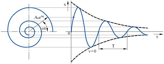
Fig. 1. Dependence of amplitude on time at damped
oscillation
3. COMPUTER
AND EXPERIMENTAL APPLICATION ON THE REAL BRIDGE CRANE
Basic data about the
electrical bridge crane under examination:
Capacity Q = 500,000 N
Span of the crane L = 28,200 mm
Crane travel speed vtravel = 0.416 m/s
Lifting speed vlift = 0.0333 m/s
Trolley mass mtrolley = 6,680 kg
Main girder gravity G1 = 294,800 N
Main cross beam gravity G2 = 41,240 N
The calculated static values of the cross-section for the main girder
without stiffeners and the rails are illustrated in Fig. 2.
3.1. Calculating damping for the steel supporting crane
structure
According to STN 27 0103 titled “Design of
crane steel structures” – Calculation by limit states, Article X
– Steel supporting structure calculation based on the II. group of the
serviceability limit states – deformation: deformation and oscillation
damping must not affect operational safety and must not interfere with proper
crane function in regard to its work specifications”. The recommended
approach to the bridge crane evaluation is outlined in Annex VIII of the
referenced standard.
The new shape of the girder caused by
deformation is not detrimental to the operation if the deflections are smaller
than the recommended values outlined in [28] and are
caused by a random nominal loading, which includes as follows:
·
rated loading,
·
constant loading,
·
loading brought about by
natural mass, and the movable parts, which move in relation to the movement of
the load.
|
|
zT = 812.5 mm A = 55 556 mm2 Jy =
2.2396 x 1010 mm4 Jz = 4.
396 x 109 mm4 |
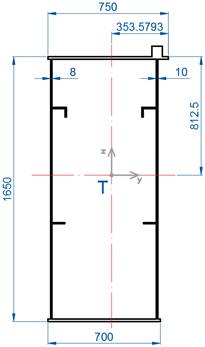
Fig. 2. Cross-section view of the
main girder in the bridge crane
For the electrical bridge crane (50t x 28.2 m)
with two main girders, along the top of which the trolley travels, the ratio
between the maximum deflection from random nominal loading in relation to
length, based on [37] can reach L/700
at most, that is, maximum deflection can reach:
![]() (18)
(18)
Such a deflection is not detrimental to the
crane operation. A steel supporting structure ought to meet the conditions of
damping while oscillating. For cranes with box girders, it is recommended that
the amplitude, after the nominal load of the oscillating bridge is set aside,
sank in the middle of the bridge within 15 s to 0.5 mm at most. The damping
time for a single-mass substitution system is determined by the following relation:
![]() (19)
(19)
![]() (20)
(20)
where
![]() is the maximum deflection of the girder from
rated loading in (mm),
is the maximum deflection of the girder from
rated loading in (mm),
f is
the frequency of natural oscillations in the girder (s-1),
![]() is
the logarithmic decrement of oscillation damping which depends on the ratio
between the girder height and length.
is
the logarithmic decrement of oscillation damping which depends on the ratio
between the girder height and length.
For the 50t x 28.2 m crane, the bridge girder height is h = 1650 mm (Fig. 2), hence, the ratio h/L = 1650/28200 = 0.0585.
Welded plate box girders are braced with a
compression boom, with a height to length ratio greater than 1:20. Based on [36], the
logarithmic damping decrement ![]() .
.
A girder spring constant can be determined by the following relation:
![]() (Nm-1)
(21)
(Nm-1)
(21)
where
E = 2.1 x 10⁵ MPa is
the elastic modulus,
L = 28 200 mm is
the bridge length,
![]() = 2.2396 x 1010 mm4
is
the axial quadratic cross-sectional moment in relation to the neutral axis.
= 2.2396 x 1010 mm4
is
the axial quadratic cross-sectional moment in relation to the neutral axis.
Then c0
= 10066619.79 Nm-1.
The reduced mass of the girder, trolley, and all
mass oscillating with the girder, once the rated load is set aside, is
determined by the following relation:
![]() (kg)
(22)
(kg)
(22)
where
q – girder mass per length (kg.mm-1),
i – number of girders along which the trolley
travels,
mtrolley – the trolley’s natural mass
without load, including the mass which the trolley retains once the load is set
aside.
To determine the reduced mass of the girders,
the gravity of the individual crane components was relayed from the static
calculation of the equipment, according to which the girder mass where there
are no crane trolley units:
![]() (kg) .
(23)
(kg) .
(23)
The second girder’s mass includes the mass
of the crane travel units, of the switchgear, of the walkway, and of the
trolley wire (relayed from the static calculation):
![]() (kg).
(24)
(kg).
(24)
If we consider that the drawing documentation
for the trolley mass mtrolley
= 6680 kg, then the reduced mass of the girder without the travel units and the
walkway is:
![]() (kg)
(25)
(kg)
(25)
and for the girder with the travel units:
![]() (kg) .
(26)
(kg) .
(26)
The relationships (20) and (21) are used to
determine natural frequencies of the respective beams f1 = 4.847 Hz, f2
= 3.142 Hz.
Damping period of the respective girders
established from the value of the maximum static deformation from the rated
load is as follows:
![]() (mm) .
(27)
(mm) .
(27)
The damping period for the first and the second
girder equals:
![]() ,
,
![]() .
(28)
.
(28)
Because the damping period in both cases is
shorter than 15 s, the steel supporting crane structure meets the conditions
for the oscillation damping according to [36].
3.2. Experimental evaluation of damping in a steel supporting
crane structure
Fig. 3 shows the strain-gauge measurement that
was proposed and made on the electrical bridge crane with box girders. The
proposed methodology enables us to determine the stresses and to identify the
extent of the deflection caused by the suspended load, the amplitude of the
oscillating bridge in the middle of its span after unloading or lifting the
load, and the time of amplitude damping required for reaching a 0.5 mm
oscillation. Furthermore, Fig. 3 shows where the sensors were applied in a
diagram. Strain-gauge sensors were placed on the edges of the top beam flange
along the axis of the bridge symmetry. To measure, we used HBM strain-gauge
sensors, bonding cement (X60), measuring apparatus (Spider8) and the evaluation
software (Catman) also from HBM.
Strain-gauge measurement was made under the
following loading:
·
loading of the crane with a
trolley without load,
·
loading with a 48,000 kg load.
The measuring apparatus was balanced in the
empty trolley mode in the middle of the bridge length. The measured incremental
values of relative deformation were used by the Catman software to evaluate and
visualise time changes of normal stress increments in the points illustrated in
Fig. 3.
The measured time sequences of the relative
deformation were used to calculate normal stresses in the points of the
single-axis stress of the main girder.
Fig. 4 illustrates the time changes of
incremental stress during intermittent lifting of the 48,000 kg load in the
points of measurements 1, 2, 3 and 4.
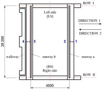
Fig. 3. Sensors in position on the crane
Because the load consisted of long slabs, which
could touch the ground at the start of the lift, the dynamic behaviour was
different from the repeated start of lifting if the load is suspended on a wire
rope.
A detailed examination of the time sequences
suggests that the extent of the oscillation amplitude at repeated lifts changes
with the length of the wound wire rope.
The measurement mode ends when the load is
lowered, during which the process of girder completing the oscillation does not
align with the theory of damped oscillation.
It is caused by the fact that the load touched
the ground again with some of its ends, and only then the load was completely
lowered onto the ground.
Damping is also affected by the suppleness of
the wire rope, which significantly reduces the time of damping to the required
amplitude.
With regard to the evaluation of the oscillation
amplitude and the damping time to the permissible 0.5 mm oscillation range
amplitude specified in [36], it is necessary to transform the stress time
sequence in the girders as shown in Fig. 4 into deforming the structure, that
is, into deflection time sequences.
Due to the small 1,390 mm trolley wheelbase and
the 28,200 mm bridge length, concentration of load mass into a point in the
middle of the bridge length.
Deflection in the middle of the girder w:
![]() (29)
(29)
where:
F – weight of half a load Q = 470,880 N,
L – bridge length 28,200 mm,
z – distance from the neutral axis to the top
beam flange,
![]() – measured relative
deformation in the point where the strain-gauge sensor is located,
– measured relative
deformation in the point where the strain-gauge sensor is located,
E – elastic modulus for the girder material,
![]() – stress in the point
where the strain-gauge sensor is located is equal.
– stress in the point
where the strain-gauge sensor is located is equal.
![]() (MPa).
(30)
(MPa).
(30)
Fig. 5 shows the time sequence of the deflection in the interval between 26
and 91 s for the sensor no. 2 in the time sequence of the crane girder
deflections brought about by the 48,000 kg load established from the
measured values in the measurement points 1, 2, 3 and 4 corresponding to the stress
increments.
The relation (29) considers the cross-section according to Fig. 2, where
the cross-sectional characteristic similarly considers the rail, the top and
the bottom longitudinal stiffening.
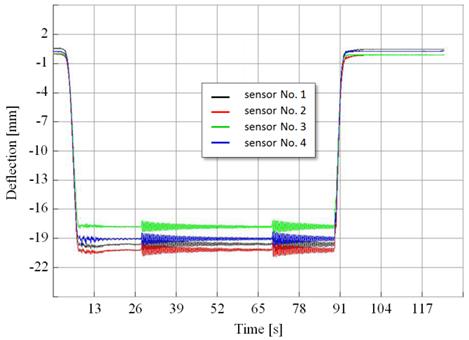
Fig. 4. Time dependence of deflections
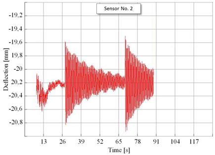
Fig. 5. Measurement interval for sensor No. 2
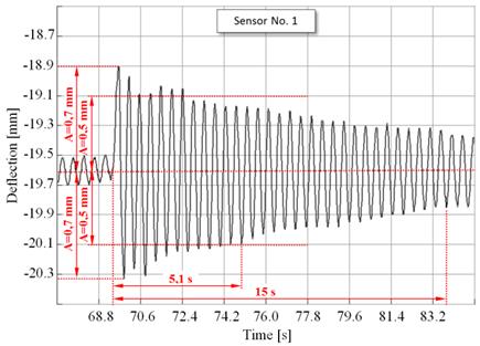
Fig. 6. Time sequence of deflections (Sensor No. 1)
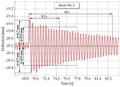
Fig. 7. Time sequence of deflection (Sensor No. 2)
3.3. Strain-gauge measurement evaluation
Figs. 6 and 9 show selected intervals of deflection time
sequences established from stresses at lifting from Fig. 4, which can be used
to determine the system dynamic characteristics. It involves determining the
natural angular frequency with respect to damping, natural frequency, and
natural oscillation period while considering the real damping in the girders
and in the mutual relations. The diagrams shown in Figs. 6 to 9 clearly depicts
the following periods of natural girder oscillation for the individual girders:
T1 = 0.4s and T2 = 0.47s. The amplitude sequence of the consecutive cycles
can be used to establish the logarithmic damping decrements, which is, however,
contingent on the potential influence of the oscillation amplitude. It is
necessary to state, however, that the values established by the strain-gauge
measurement are affected by the measure of suppleness, or conversely, the
stiffness of the wire rope, which translates into these quantities.
The values of cycle period established
experimentally are greater than the values acquired by the analytical
calculation. Other quantities are tied to the value by a precisely defined
dependence, and therefore, do not require further commentary.
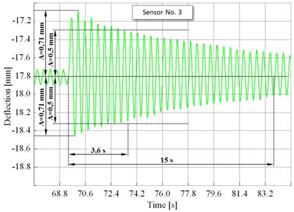
Fig. 8. Time sequence of deflections (Sensor No. 3)
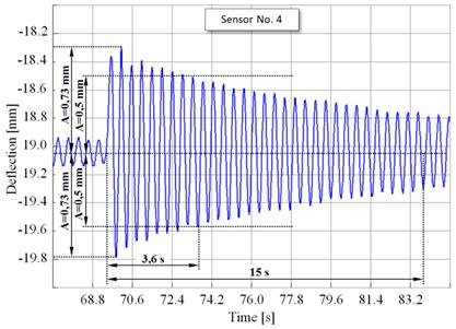
Fig. 9. Time sequence of deflections (Sensor No. 4)
3.4. Strain-gauge measurement evaluation
Figs. 6 and 9 show selected intervals of deflection time
sequences established from stresses at lifting from Fig. 4, which can be used
to determine the system dynamic characteristics. It involves determining the
natural angular frequency with respect to damping, natural frequency, and
natural oscillation period while considering the real damping in the girders
and in the mutual relations.
The diagrams shown in Figs. 6 to 9 clearly shows the
following periods of natural girder oscillation for the individual girders: T1 = 0.4s and T2 = 0.47s. The amplitude sequence of the consecutive cycles
can be used to establish the logarithmic damping decrements, which is, however,
contingent on the potential influence of the oscillation amplitude.
It is necessary to state, however, that the
values established by the strain-gauge measurement are affected by the measure
of suppleness, or conversely, the stiffness of the wire rope, which translates
into these quantities. The values of cycle period established experimentally
are greater than the values acquired by the analytical calculation. Other
quantities are tied to the value by a precisely defined dependence, and
therefore, do not require further elaboration.
4. SUMMARY AND CONCLUSION
When the structures are evaluated by
serviceability limit states and they are accessible by the operators or the
public, they must be designed to prevent personal discomfort (ex. natural
frequencies of the internal organs that are identical to the frequency of the
structure) caused by the dynamic effects of loading expressed by acceleration
(or speed) and frequency.
The crucial natural frequencies of the structure
and its parts ought to be sufficiently different from the frequencies of the
actuating forces to prevent resonance, which is also especially important from
the perspective of structural fatigue loading.
The standard [36] lists that
there are two limit values of natural frequency and specifically 3 and 5 Hz. It
also states that for the girders with a span L ≤ 10m, the criteria could be deemed met if the specified
extent of the deflection does not exceed 10 or 28 mm. It also points out that
in special cases, a dynamic calculation is needed to show that the resulting
acceleration and the frequency do not cause significant personal discomfort or
failure of the equipment or its parts. Furthermore, the value of relative
internal resistance is affected in no small measure by the losses of overcoming
passive resistance in relations between structural elements, which the
experimental measurement confirmed as well.
It follows that in fact, these relative
quantities of internal resistance are greater; hence, the greater values of the
logarithmic damping decrement. These are the actual reasons why it is
impossible not to take into consideration Section X
and Annex No.VII from the standard [36]. It can be concluded that provided the steel
supporting structure of the bridge crane complies strength-wise, it complies
also in terms of the second limit state of deformation and damping.
Acknowledgements
This article was elaborated in the framework of
the Grant Project VEGA 1/0110/18.
References
1.
He
Wei. 2018. „Vertical dynamics of a single-span beam
subjected to moving mass-suspended payload system with variable speeds”. Journal of Sound and Vibration 418:
36-54. ISSN: 0022-460X. DOI: https://doi.org/10.1016/j.jsv.2017.12.030.
2.
Michaltsos
George, Dimitrios Sophianopoulos,
Anthony Kounadis. 1996. „The effect of a moving mass and other parameters on the
dynamic response of a simply supported beam”. Journal of Sound and Vibration 191(3): 357-362. ISSN: 0022-460X.
DOI: https://doi.org/10.1006/jsvi.1996.0127.
3.
Wu
Jia-Jang. 2005. „Dynamic analysis of an inclined beam
due to moving loads”. Journal of
Sound and Vibration 288(1-2): 107-131. ISSN 0022-460X. DOI: https://doi.org/10.1016/j.jsv.2004.12.020.
4.
Fodor
Szabol, Carlos Vázquez, Leonid Freidovich, Nariman Sepehri. 2016. „Towards oscillation reduction in
forestry cranes”. BATH/ASME 2016
Symposium on Fluid Power and Motion Control. University of Bath, UK. 7-9
september 2016, Bath, UK. ISBN: 978-07918-5006-0. DOI: https://doi.org/10.1115/FPMC2016-1792.
5.
Hussien
Sharifah Yuslinda Syed, Rozaimi Ghazali, Hazriq Izzuan Jaafar, Chong Chee Soon.
2016. „Analysis of 3D gantry crane system by
PID and VSC for positioning trolley and oscillation reduction”. Journal of Telecommunication, Electronic and
Computer Engineering 8(7): 139-143. ISSN: 2180-1843.
6.
Masoud
Ziyad N. 2007. „Oscillation control of quay-side container cranes using
cable-length manipulation”. Journal
of Dynamic Systems, Measurement and Control 129(2): 224-228. ISSN:
0022-0434. DOI: https://doi.org/10.1115/1.2432362.
7.
Hu
Youmin, Bo Wu, Joshua C. Vaughan, WilliamE. Singhose. 2013. „Oscillation suppressing for an energy
efficient bridge crane using input shaping”. 9th Asian Control Conference (ASCC 2013). IEEE Advancing Technology
for Humanity. 23-26 June 2013. Istanbul, Turkey. ISBN:
978-1-4673-5767-8. DOI:
http://doi.org/10.1109/ASCC.2013.6606196.
8.
Chen
Yung-Feng, An-Chyau Huang.
2014. „Oscillation
reduction for overhead cranes with time-varying payload and rope length“.
Journal of the Chinese Institute of Engineers 37(2): 259-267. ISSN: 0253-3839. DOI: https://doi.org/10.1080/02533839.2012.757049.
9.
Singhose
William, Dooroo Kim, Michael Kenison. 2008. „Input shaping control of
double-pendulum bridge crane oscillations”. Journal of Dynamic Systems, Measurement, and Control 130(3). ISSN:
0022-0434. DOI: http://doi.org/10.1115/1.2907363.
10. Kiviluoto Sami, Lasse Eriksson, Heikki
N. Koivo. 2015. „Modelling and control of vertical oscillation in
overhead cranes”. American Control
Conference: 1290-1295. AACC American Automatic Control Council. 1-3 July
2015. Chicago, Illinois. ISBN: 978-1-4799-8685-9.
11. Zrnic Nenad Dj, Vlada M. Gašic,
Srdjan M. Bošnjak. 2015. „Dynamic response of a gantry crane system
due to a moving body considered as moving oscillator”. Archives of Civil and Mechanical Engineering
15(1): 243-250. ISSN: 1644-9665. DOI: https://doi.org/10.1016/j.acme.2014.02.002.
12. Gašic Vlada, Nenad Zrnic,
Aleksandar Obradovič, Srdan Bošnjak. 2011. „Consideration of
moving oscillator problem in dynamic responses of bridge crane”. FME Transactions 39(1): 17-24. ISSN:
1451-2092. DOI: https://doi.org/10.1016/j.acme.2014.02.002.
13. Jaafar Hazriq Jaafar, Z. Mohamed, J.J.
Jamian, Amar Faiz Zainal Abidin,
Anuar Mohamed Kassim, Z. Ab Ghani. 2013. „Dynamic behaviour of a
nonlinear gantry crane system”. Procedia
Technology 11: 419-425. ISSN: 1877-7058. DOI: http://doi.org/10.1016/j.protcy.2013.12.211.
14. Hu Youmin, Bo Wu, Joshua Vaughan,
Willam E. Singhose. 2013. „Oscillation suppressing for an energy
efficient bridge crane using input shaping”. 9th Asian Control Conference (ASCC). Asian Control Association. 23
June 2013 Istanbul, Turkey. ISBN:
978-1-4673-5767-8. DOI: http://doi.org/10.1109/ASCC.2013.6606196.
15. Padula Fabrizio, Antonio Visioli,
Domenico Facchinetti, Alberto Saleri. 2015. „A dynamic inversion
approach for oscillation-free control of overhead cranes”. 20th IEEE International Conference on Emerging
Technologies and Factory Automation (ETFA
2015): 337-343. IEEE Industrial Electronics Society (IES). 08-11 September
2015, Luxembourg City, Luxembourg. ISBN: 978-1-4673-7930-4.
16. Ece Mehmet Cem, Metin Aydogdu, Vedat
Taskin. 2007. „Vibration of a variable cross-section beam”. Mechanics Research Communications 34(1):
78-84. ISSN: 0093-6413. DOI: http://doi.org/10.1016/j.mechrescom.2006.06.005.
17. Grega Robert, Jozef
Krajňák, Lucia Žuľová, Gabriel Fedorko, Vieroslav Molnár. 2017. „Failure
analysis of driveshaft of truck body caused by vibrations”. Engineering Failure Analysis 79:
208-215. ISSN: 1350-6307. DOI: https://doi.org/10.1016/j.engfailanal.2017.04.023.
18. Czech P. 2013. “Diagnosing a car engine fuel
injectors' damage”. Communications in Computer and Information Science 395: 243-250. DOI:
https://doi.org/10.1007/978-3-642-41647-7_30. Springer, Berlin, Heidelberg.
ISBN: 978-3-642-41646-0; 978-3-642-41647-7. ISSN: 1865-0929. In: Mikulski Jerzy
(eds), Activities of transport telematics,
13th International Conference on Transport Systems Telematics, Katowice Ustron,
Poland, October 23-26, 2013.
19. Czech P. 2012. “Determination of the course
of pressure in an internal combustion engine cylinder with the use of vibration
effects and radial basis function - preliminary research”. Communications in
Computer and Information Science 329:
175-182. DOI: https://doi.org/10.1007/978-3-642-34050-5_21. Springer, Berlin,
Heidelberg. ISBN: 978-3-642-34049-9. ISSN: 1865-0929. In: Mikulski Jerzy (eds),
Telematics in the transport environment,
12th International Conference on Transport Systems Telematics, Katowice Ustron,
Poland, October 10-13, 2012.
20. Haniszewski Tomasz. 2017. „Modeling the dynamics of cargo lifting process by overhead crane for
dynamic overload factor estimation”. Journal of Vibroengineering
19(1): 75-86. DOI: 10.21595/jve.2016.17310. ISSN: 1392-8716.
21. Gąska Damian, Tomasz Haniszewski. 2016.
“Modelling studies on the use of aluminium alloys in lightweight
load-carrying crane structures”. Transport
Problems 11(3): 13-20. DOI: 10.20858/tp.2016.11.3.2. ISSN: 1896-0596.
22. Haniszewski Tomasz, Damian Gaska. 2017.
“Numerical modelling of I-Beam jib crane with local stresses in wheel
supporting flanges - influence of hoisting speed”. Nase More 64(1): 7-13. DOI: 10.17818/NM/2017/1.2. ISSN: 0469-6255.
23. Kosicka E.,
Kozłowski E., Mazurkiewicz D. 2015. „The use of stationary tests for analysis of monitored residual
processes”. Eksploatacja i
Niezawodnosc – Maintenance and Reliability 17(4): 604-609.
DOI: http://dx.doi.org/10.17531/ein.2015.4.17.
24. Mazurkiewicz D. 2014. „Computer-aided
maintenance and reliability management systems for conveyor belts”. Eksploatacja i Niezawodnosc – Maintenance and
Reliability
16(3): 377-382.
25. Mazurkiewicz D. 2010. „Tests of extendability
and strength of adhesive-sealed joints in the context of developing a computer
system for monitoring the condition of belt joints during conveyor
operation”. Eksploatacja i
Niezawodnosc – Maintenance and Reliability 3: 34-39.
26. Czech P. 2011. “Diagnosing of disturbances in
the ignition system by vibroacoustic signals and radial basis function -
preliminary research”. Communications
in Computer and Information Science 239: 110-117. DOI:
https://doi.org/10.1007/978-3-642-24660-9_13. Springer, Berlin, Heidelberg.
ISBN: 978-3-642-24659-3. ISSN: 1865-0929. In: Mikulski Jerzy (eds), Modern transport telematics, 11th International
Conference on Transport Systems Telematics, Katowice Ustron, Poland, October
19-22, 2011.
27. Czech
Piotr. 2011. „An intelligent approach to wear of piston-cylinder assembly
diagnosis based on entropy of wavelet packet and probabilistic neural networks”.
Communications in Computer and
Information Science 239: 102-109. DOI:
https://doi.org/10.1007/978-3-642-24660-9_12. Springer, Berlin, Heidelberg.
ISBN: 978-3-642-24659-3. ISSN: 1865-0929. In: Mikulski Jerzy (eds), Modern transport telematics, 11th International
Conference on Transport Systems Telematics, Katowice Ustron, Poland, October
19-22, 2011.
28. Bajkowski Jacek Mateusz, Bartlomiej
Dyniewicz, Czeslaw I. Bajer. 2015. „Damping properties of a beam
with vacuum-packed granular damper”. Journal
of Sound and Vibration 341: 74-85. ISSN: 0022-460X. DOI: https://doi.org/10.1016/j.jsv.2016.05.006.
29. Balamurugan Varadarajan, Sadagopan
Narayanan. 2002. „Active-pasive hybrid damping in beams with enhanced
smart constrained layer treatment”. Engineering
Structures 24(3): 355-363. ISSN: 0022141-0296. DOI: https://doi.org/10.1016/S0141-0296(01)00101-8.
30. Blackbur D., W. Singhose, J. Kitchen,
V. Patrangenaru, J. Lawrence, T. Kamoi, A. Taura. 2010. „Command shaping
for nonlinear crane dynamics”. Journal
of Vibration and Control 16(4): 477-501. ISSN 1077-5463. DOI: http://doi.org/10.1177/1077546309106142.
31. Tweten Denis. J., Zach Ballard, Brian
P. Mann. 2014. „Minimizing error in the logarithmic decrement method
through uncertainty propagation”. Journal
of Sound and Vibration 333(13): 2804-2811. ISSN: 0022-460X. DOI: https://doi.org/10.1016/j.jsv.2014.02.024.
32. Magalas Leszek B., T. Malinowski. 2003.
„Measurement techniques of the logarithmic decrement”. Solid State Phenomena 89: 247-260. ISSN:
1662-9779. DOI: https://doi.org/10.4028/www.scientific.net/SSP.89.247.
33. Stanislawczyk A. 2006. „Advanced
techniques for determining high and extreme high damping: OMI – a new
algorithm to compute the logarithmic decrement”. Key Engineering Materials 319. ISSN: 1662-9795. DOI: https://doi.org/10.4028/www.scientific.net/KEM.319.231.
34. Magalas Leszek B., Mariusz Majewski.
2015. „Hilbert-twin-a novel hilbert transform-based method to compute
envelope of free decaying oscillations embedded in noise, and the logarithmic
decrement in high-resolution mechanical spectroscopy HRMS”. Archives of Metallurgy and Materials
60(2): 1091-1098. ISSN: 1733-3490. DOI: 10.1515/amm-2015-0265.
35. Lan Qingqun, Manicka Dhanasekar,
Yunendar Aryo Handoko. 2019. „Wear damage of out-of-round wheels in rail
wagons under braking”. Engineering
Failure Analysis 102: 170-186. ISSN: 1350-6307. DOI: https://doi.org/10.1016/j.engfailanal.2019.04.019.
36. STN 27 0103: 1989. Navrhování ocelových konstrukcí
jeřábů. Výpočet
podle mezních stavů. Praha. Úřad pro normalizaci a
měření. [In Slovak: STN 27 0103: 1989. Design of Steel Crane Structures. Calculation According to Limit States. Praha. Czech Office for Standardisation and Measuring].
37. DIN 15 018: 1984. Krane. Grundsätze für
Stahltragwerke. Berechnung. Berlin. Deutsches Institut für Normung.
[In German: DIN 15 018: 1984. Cranes. Steel Supporting Structures. Calculations. Berlin.
German Institute for Standardisation].
Received 11.03.2020; accepted in revised form 12.05.2020
![]()
Scientific
Journal of Silesian University of Technology. Series Transport is licensed
under a Creative Commons Attribution 4.0 International License