Article
citation information:
Puškár, M., Kopas, M.,
Puškár, D., Šoltésová, M. Influence of various
homogenisation system configurations on output parameters of an experimental
engine. Scientific Journal of Silesian
University of Technology. Series Transport. 2020, 107, 135-152. ISSN: 0209-3324. DOI: https://doi.org/10.20858/sjsutst.2020.107.10.
Michal PUŠKÁR[1],
Melichar KOPAS[2], Dušan
PUŠKÁR[3], Marieta
ŠOLTÉSOVÁ4
INFLUENCE
OF VARIOUS HOMOGENISATION SYSTEM CONFIGURATIONS ON OUTPUT PARAMETERS OF
AN EXPERIMENTAL ENGINE
Summary. This article analyses the influence of various
configurations concerning the homogenisation system on the output parameters of
an experimental engine. The results presented in this article were obtained
using experimental dynamometric measurement. A modular approach to the
individual measurements consists of a sequential formation of the
homogenisation system configurations. The experimentally obtained results are
matches with the analytical relations, which are described in the related
literature. These results can be presented for a wide spectrum of high-powerful
engines because the homogenisation system does not depend on the construction
and design arrangement of the engine itself. The analysed system was
successfully applied in the motorcycles and it is a subject of the patent
application.
Keywords: homogenisation system, output parameters,
experimental engine
1. INTRODUCTION
In
this paper, results from the measurement of a high-powerful racing combustion
engine are presented. These results were obtained by means of the system
EW&C, which is operating as the data-recording process. This measuring
equipment senses and records information during the engine working operation
under real conditions and operational loading. A modular approach to the
individual measuring consists of a sequential assembly of the individual
components belonging to the engine inlet and exhaust system. An investigation
of the individual configuration influences of both systems is performed by
means of the sequential experimental measuring. The measurement of the exhaust
pipe was based on the application of a tuned racing exhaust system. To perform
experiments oriented to the inlet system, a new system of the thrust-ejector
suction was developed to solve problems connected with an insufficient feeding
of a cylinder with a fresh mixture. The pressure of air, which is sucked into
the engine, is changed from the atmospheric value to the overpressure level.
This phenomenon causes an increase of the engine power output and torque.
According to the gained results, a relation between the newly developed inlet
pipe and increasing of the engine torque was investigated. Furthermore, the
experimentally obtained results align with the analytical relations described
in the relevant literature. These results can be presented for a wide spectrum
of high-powerful engines because the air inlet system is independent on the
engine design and arrangement. The analysed system was successful in the
motorbike applications. This can be seen in the positive results registered in
the previous year as well as the patent application concerning this new design
arrangement
2. EXPERIMENTAL MODEL AND MEASURING
DEVICES
An analysis of
the engine performance, as well as criteria for development of the inlet and
exhaust pipe system, require deep knowledge of acoustics of both systems. The
up-to-date known information from this area can be summarised into several
conclusions.
In many
scientific articles, experimental results and theoretical models of the
acoustic waves and their impact on global efficiency of the piston combustion
engines are presented. The fundamental information sources about the instable
gas dynamics in internal distribution channels of combustion engines were
presented during the ’50s of the last century. Measuring methods of the
local throughput in the pipe, together with computerised calculations, were
improved considerably during the ’80s [1]. A complete overview of topical
knowledge oriented to the analysis and proposal of the inlet (suction) and
exhaust systems of the internal combustion engine was published at the end of
the ’90s [2]. The theoretical Principia of one-dimensional acoustic
models were described at the turn of the centuries. Then, the more complicated
non-linear dynamic gas models were successfully transformed into simpler linear
acoustic models [3, 4].
Very interesting
results were obtained also by means of the Euler's equation solution for a
pipe. This solution offered a high level of result reliability [5]. A principle
of this methodology consists of solution of velocities and pressure equations
with regard to the frequency using a method of matrix transfer, taking into
consideration the theoretical limits for real values of the high-pressure
levels in the exhaust gas system. This solution seems to be the most suitable
method for analysis of the inlet and exhaust system with regard to noise
reduction [6].
Some scientific
works demonstrate acceptable conformity of the linear acoustic models with the
experiments performed in the inlet and exhaust pipe of the piston combustion
engines [7]. A wide range of the experimental tests and practical applications
support the development criteria for the proposal of new theories. There are
consistent efforts at integrating results obtained from research activities
performed in the area of resonance and acoustic feedback among the inlet parts.
Similarly, the abovementioned amount of information enables proposal of new
methods for the projection of the inlet and exhaust systems of the piston
engines [8].
A complex view
on design and simulation of the high-power engines, including a proposal of the
empirical methods for designers as well as the experimental data on the
efficiency of the high-speed engines are summarised in the literature [9].
In spite of the
present large amounts of publications and professional articles, only a small
amount of measured data concerning mutual interrelations and influences among
the individual parts of the inlet system are available. An arrangement of the
inlet system is independent, usually on a constructional and technological
conception of the engine itself in the case of high-power combustion engines.
This article presents an experimental study of the high-power combustion engine
applied in the motorbike, specified for racing purposes. In this article, the
influence of the various inlet and exhaust systems, as well as their individual
components on the volumetric efficiency, was investigated. This investigation
was performed by means of various measurements using a data-recording system.
Several various
inlet and exhaust system configurations were tested during this research
process. The final complete configuration of the inlet system presented in Fig.
1, is a result of our own long-time development process. Another output of the
successful development activities is the patent application of this invention
that was registered in the previous year. This patent concerns a conceptual
arrangement of the newly developed system.
This
experimental analysis was realised according to various remarks and problem
solutions occurring during realisation of various engine design [10].
The high-power racing
motorbike engine was chosen for practical tests to perform individual
experimental measurements. This engine is based on a serial engine production.
2.1. Inlet and Exhaust Systems
Motorcar engines usually use a system of supercharging that is based on turbine driven by exhaust gases, that is, turbocharging or turbo. This system can also be applied in motorbike engines, however, with various attendant problems with the final supercharging effect becoming insufficient. A possible solution to this task offers a system of thrust loading suction, which is applied for high-power motorbike engines due to its simplicity. A disadvantage of such solution is a fact that the sufficient level of overpressure, which is necessary for the production of an efficient engine power output, is generated only at high-speed levels of the vehicle (over 120 km·h-1 at least and over 150 km·h-1 in an ideal case). If the speed value is under these limits, the effect is almost none and vice-versa in such a situation, an undesirable under-pressure in the intake system would occur.
It is necessary, therefore, to develop a new system that will be able to generate the required effect of the pressurised air inlet during lower speeds as well as without the motion of the vehicle.
The newly developed inlet system installed in the engine, together with the resonance exhaust system as well as the motorbike silhouette are visible in Fig. 1. The blue arrows mark flows of fresh incoming air; the red arrows illustrate the streaming of exhaust gases in the resonance exhaust system. This inlet system is a subject of the registered patent application with the title “System of the thrust-ejector suction”. This invention consists of the following design proposal: the suction inlet (1) is installed at the frontal surface of the vehicle. The suction inlet is connected with the inlet pipe (2), which is jointed with the ejector (3). The ejector is fixed to the compression pipeline (4). The compression pipeline is connected air-tightly with the air accumulator (airbox) (5) and with the diffuser of the carburettor coming to the airbox.
Fig. 1. The developed inlet system with the engine and
resonance exhaust system
A supposed advantage of this construction is the possibility of partial supercharging of the vehicle in a static state. This assumption is based on the results obtained during testing of the engine prototype equipped with this new system. It was necessary to increase the amount of the delivered fuel during stationary measurements on the engine power brake because the new system reduced the fuel mixture as a result of the pressurised air inlet. The increasing values of the engine torque were recorded by means of the data-recording during the performed experiments (Fig. 14).
Fig. 2 offers a more complex description of the individual parts of the inlet and exhaust system. The complete inlet system with the external and internal air part is divided into the three main subsystems: the secondary pipeline, the airbox and the primary pipeline. The secondary pipeline feeds outer air from the frontal surface of the motorbike to the airbox. The airbox is an airtight box, which connects the secondary pipeline with the primary pipeline including the carburettor and the set of membrane suction valve. The geometrical characteristics of the inlet and exhaust channels in the engine cylinder were modified to improve the aerodynamic power output.
The exhaust pipe is a classic resonance exhaust system with the components described in details in Fig. 2.
Tab. 1 presents the main dimensions of the inlet and exhaust system of this engine. The silencer is an absorptive type made from external steel shell with thickness 1 mm. It is filled by an absorptive inlet, which covers the steel tube with the perforated middle part.
Fig. 2. Components of the intake and exhaust system
3. MEASURING EQUIPMENT
The engine was tested in a real loading by means of an EW&C system. It is a data-recording system, that is, a piece of equipment, which senses information during the engine working operation under real conditions and it simultaneously saves (recording), the necessary information into the internal memory. The data-recording system enables monitoring of all important combustion engine parameters, namely; the engine power output and the engine torque in dependence on the engine speed. Also, the exhaust system temperature and its time behaviour are measured as well as many other parameters. The concrete number and kind of recorded parameters depend on the type and amount of sensors installed in the given engine. Fig. 3 illustrates a fundamental scheme of the equipment used for data measuring, elaboration and evaluation.
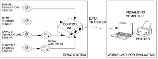
Fig. 3. Scheme of the EW&C system
It is evident from this figure that the principle of this system operation consists of monitoring of the actual engine speed, the temperature of the exhaust system and the speed gear. An additional input parameter is the throttle position in the carburettor. The measuring system is able to create a record of the current engine operation by means of the abovementioned measured data taking into consideration the next supplemental information (for example, the wheel circuit, gear ratios of the individual speed gears, the curve of air resistance and mass of the motorcycle). This operational record is continuously saved to the system internal memory and copied into the PC after measurement. The time behaviour of the engine operation is displayed on the monitor. Each point of the obtained record represents a multi-functional source of information about the momentary speed, exhaust system temperature and the engine power output, which is measured on the crankshaft.
In the framework of the whole speed spectrum range, it was necessary to conduct several tests to perform the power output analysis of the various inlet and exhaust system configurations. Every measurement had to be repeated three times at least for accuracy verification and reliability. All tests are running at the 4th speed gear, which ensures operational stability in the whole speed spectrum considering the special racing requirements. The experimental measurements presented in this paper are described in the form of the output diagrams created according to the similarity of two basic parameters: the break mean effective pressure bmep and the piston speed um. The diagrams are assembled using the factor values bmepmax = 1.77 MPa and ummax = 21.6 m·s-1, that is, by means of the maximum values of the break mean effective pressure and the piston speed. These data were obtained from the engine testing at the 4th speed gear and after the specific racing adjustment. A sketch of the appropriate testing configurations of both systems is a component part of the characteristics. All the relevant relations between the engine power output and the engine speed as well as between the engine torque and the engine speed can be obtained from the abovementioned curves.
4. MEASURING EQUIPMENT
Numerous design configurations were tested to analyse the influence of the inlet and exhaust system components. These systems were disassembled into the individual parts first. Thereafter, the individual components were mounted together into the partial systems and in this way, the final configuration was designed as illustrated in Fig. 2.
Fig. 4. Scheme of the inlet and exhaust pipe
Fig. 5. Main dimensions of the inlet and exhaust pipe
Tab. 1
Main dimensions of
inlet and exhaust system
|
System |
Subsystem |
Mark
(Fig.
4, 5) |
Length
[mm] |
Input diameter [mm] |
Output diameter [mm] |
||
|
Inlet |
External air section |
Inlet port |
Fi |
40 |
70 |
65 |
|
|
Inlet pipe |
Ei |
270 |
65 |
65 |
|||
|
Ejector |
Ci |
75 |
65 |
40 |
|||
|
Di |
25 |
40 |
40 |
||||
|
Compress pipe |
Bi |
475 |
65 |
65 |
|||
|
Connecting pipe |
Ai |
75 |
65 |
55 |
|||
|
Air filter |
|
Length x Width x High (185 x
110 x 200) [mm] |
|||||
|
Internal air path |
Primary pipe (Include carburettor) |
Primary |
200 |
28 |
55 |
||
|
Exhaust |
Primary pipe |
Standard |
Ae |
430 |
40 |
75 |
|
|
Trim |
420 |
||||||
|
Expansion cone |
Be |
178 |
75 |
130 |
|||
|
Cylinder part |
Ce |
98 |
130 |
130 |
|||
|
Compression cone |
De |
210 |
130 |
24 |
|||
|
Exhaust pipe |
Ee |
82 |
24 |
24 |
|||
|
Silencer |
Fe |
200 |
24 |
24 |
|||
The
scheme of the inlet and exhaust pipe is depicted in Fig. 4. The secondary inlet
pipe is presented in the upper part of the figure and the exhaust system at the
bottom part. Both pipelines are divided into subsystems, marked Ai,e –
Fi,e. The main dimensions of all pipe subsystems are given in Tab. 1. Following
these dimensions, a graphical dependence between the pipe diameter and its
distance from the cylinder was created. This relation is visible in
Fig. 5.
The
complete configuration of the inlet and exhaust system is shown in Fig. 2. The
configuration was chosen to obtain more information about the engine power
output of the inlet and exhaust pipe. The output information obtained from this
configuration, including values of the optimal temperature interval (Fig. 6),
was compared with the outputs from other subsystem configurations or with other
temperature intervals, (Figs. 6-13).
Taken
into consideration a linear relation between the bmep and the torque, the peaks
of the bmep correspond to the maximums of the torque and efficiency. This is
neglected in this case resulting in a reduction in the engine speed due to
mechanical loses. It is possible, therefore, to estimate the peaks of the
curves by means of the simplified equations derived from the theoretical wave
models [2]. The ideal natural frequencies typical for the inlet system of
combustion engines are calculated in the literature [10]. The inlet of air from the primary pipe
is jointed with the secondary pipe by means of the connecting chamber
(airbox). During the suction time,
a wave effect is generated, which creates a maximal volumetric efficiency of
the air inlet.
The
maximal wave frequencies can be approximated according to the following
Equations 1 and 2:
![]() (1)
(1)
![]() (2)
(2)
where:
ω is the natural
frequency of the system,
lp and lsec are the primary and
secondary lengths of pipes in section Apr
and Asec,
Vpl is the volume of
the connecting chamber between the primary and the secondary tube,
cs is the speed of
sound.
Equation
2 does not offer any useful information in this case because the frequency
value ω for the whole system is deep under the minimal operational speed
of the engine. Instead, the air streaming is illustrated in Fig. 1 by means of
the primary pipe length. Furthermore, Equation 1 enables to define the maximum
point of the volumetric efficiency.
The
wave effect is able to increase the volumetric efficiency because it generates
the resonance phenomena as a result of the pressure impulses arising during
closing of the membrane valve. The newest publication [12] defines Equation 3
of speed Ni for variable
parts of the inlet pipe, where ni
is a number of pressure impulses entering the pipe during 720° rotation of
the crankshaft:
 (3)
(3)
where:
lp is the total pipe
length, which is divided into the j pipe subsystems with the constant section Ai and length each of them is
Kjlp,
Ap is the piston
area,
um(Ni) is the
piston speed.
The
number and position of the impulse peaks can be defined by means of Equation 2.
It is possible to say, according to our experiences, that this simplified
relation also requires an additional tuning. However, it should be sufficient
for a practical proposal of the racing engine pipes.
5. ACOUSTICS IN EXHAUST PIPE
The
silencer influence on the torque during the optimal operational temperature
using the complete set of the inlet and exhaust system is demonstrated in Fig.
9. A relevant difference among the braking torque values without and with the
silencer was not observed. Some deviations are visible but they are in limits
and can be regarded as measuring errors. This system arrangement is useful only
for obtaining information and it is not applicable for practical purposes due
to noise restrictions. Equation 3 is valid for the inlet pipe. The simplified
analytical Equation 4, is appropriate for tuning of the exhaust pipe:
 (4)
(4)
The
tuning regime N with the 83% value of
the ummax (peak on the right in Fig. 6) is an assumption for
Equation 4, whereas the average value of the exhaust gas temperature Te is from
the interval 520°C÷620°C and the length of the exhaust gas is
le. The initial analysis of the exhaust system was oriented to the
determination of an optimal temperature interval in the exhaust system.
The
speed of sound waves increases when the temperature is higher. This fact is in
accordance with the theory of waving considering the relation (5) between the
speed of sound waves and the air temperature:
![]() (5)
(5)
where:
C is the speed of
sound waves,
K = 1.4,
R is the universal
gas constant,
T is the
temperature,
M is the molar
mass.
If the
exhaust pipe is defined with regard to its shape and dimensions, hence, in this
case, there exists theoretically such temperature interval, which is limited by
the maximum and minimum temperature values. The output engine characteristics
are optimal in this interval. With regard to this assumption, the measurements
focused on determination of the temperature interval were performed; this is
optimal for the given exhaust system. The thermal sensor was installed in the
point of maximal temperature in the exhaust system, that is, in the area of the
primary pipe, approx. 150 mm from the upper edge of the exhaust channel (Fig.
2).
The
increasing temperature of the exhaust system accelerates the resonance wave
propagations. The back-wave in the exhaust pipe is returning faster. This way,
the process of the cylinder reverse scavenging is also accelerated and the
exhaust pipe is shortening theoretically. If the engine speed is increasing
during the optimal regime, then the exhaust system temperature must be higher.
Thus, the exhaust system is shorter theoretically at higher speed and longer
theoretically (with a lower temperature) in slower engine speed.
Fig. 6
graphically illustrates a comparison of the output parameters of the complete
inlet and exhaust pipes for two various temperature intervals. The vertical
axis represents a ratio between the break mean effective pressure bmep and the
maximum of the break mean effective pressure bmepmax, that is, the ratio value bmep/bmepmax. The horizontal
axis represents a ratio between the piston speed um and the maximum of the
piston speed ummax, that is, the ratio value um/ ummax. The
continuous curve describes the output parameters for the exhaust system
temperature interval between 520°C and 620°C. The dashed curve is valid
for the interval between 420°C and 520°C.
A
significant difference among the output parameters is visible after comparison
of both curves. The optimal output values are reached in the temperature
interval between 520°C and 620°C. The engine torque is reduced
significantly to the level 75% of the um/ummax
if the temperature is below 520°C. The output characteristic is improved up
to the level 90% of the um/ummax.
Another problem is in the point 95%, where the torque is dropped steeply. This
phenomenon causes braking of the engine and it can be critical for the racing
engines because the sudden decrease of the torque arises in the framework of
the operational speed range. The Fig. 7 compares the output parameters for the
temperature interval of the exhaust pipe between 520°C to 620°C with
the output parameters for higher temperatures, specifically from 620°C to
720°C. The differences among the output parameters are also important in
the case of overcooled exhaust system (Fig. 6). If the exhaust pipe is
overheated, then the engine torque rises up to level 68% of the um/ummax, which is
analogous to the optimal temperature interval. The characteristic is improved from 68%
up to 75% and after this point, it declines steeply to the local minimum value.
After this decline, the curve rises again up to peak 92%, which is identical to
the compared temperature interval between 520°C and 620°C. According to
the analysis of the obtained results, it is possible to say that for this
engine, the optimal interval of operational temperatures in the exhaust pipe is
from 520°C to 620°C. However, in the limit points of this temperature
interval, that is, in the points 520°C and 620°C the output
characteristics are not optimal. The best behaviour of the torque is reached in
the middle value of the temperature interval, that is, at point 570°C.
Between 420°C and 520°C, the exhaust system overcooled. The engine
characteristics are improved significantly for higher temperatures and the
exhaust pipe is shortened theoretically. The output characteristic is
relatively suitable between 620°C and 720°C despite the fact of reduced
torque at 68% of um/ummax. This
statement is true, especially for temperature 620°C. If the temperature
increases further, the system becomes overheated and the exhaust pipe is
enormously theoretically shortened. The optimal value of the exhaust system
temperature was applied in all of the next experimental measurements (Fig.
8-14) and the curve obtained between the temperatures from 520°C to
620°C (Figs. 6 and 7) served as the base for the next comparisons.
Fig. 8
illustrates the comparison of output parameters for the complete system of the
inlet and exhaust pipe, however, in the second case the exhaust pipe is
shortened about 10 mm in the primary pipe area. The continuous curve represents
a comparative output of the complete system at optimal operational interval.
The dashed characteristic means an output of the shortened exhaust pipe
according to the scheme in the bottom part of Fig. 8. It is evident from the
comparison of these characteristics that the output curve was shifted into the
area of higher engine speed due to shortening of the exhaust pipe. The maximal
peak was shifted to the right about approx. 4% of the um/ummax.
The
fourth graph concerning the exhaust system is in Fig. 9. It is focused on the
influence of the silencer on the output characteristic. The output
characteristic of the complete system without the silencer is dashed. Both
comparative curves are almost identical. Removing the silencer caused a drop of
the engine torque at value interval from 60% to 66% of the um/ummax.
Fig. 6. Dimensionless bmep for various temperature states
of the exhaust system
Fig. 7. Dimensionless bmep for various temperature states
of the exhaust system
Fig. 8. Dimensionless bmep for various lengths of the
exhaust system
Fig. 9. Dimensionless bmep for various arrangements of the exhaust system
6. INFLUENCE OF THE INLET SYSTEM
Application
of turbocharging for motorbike engines is problematic; therefore, the thrust
loading system is used. This system has its own disadvantages, however, the
thrust-ejector suction system was subsequently developed and patented (Fig. 2).
This system was applied for the racing motorbike (Fig. 1). The main idea of
this new solution is its use for the suction process, the phenomenon of the
exhaust gases oscillation, which is typical for the exhaust pipe. The principle
of the thrust-ejector system is as follows: the suction air flows through the
inlet hole (1) due to underpressure. The air streams in the inlet pipe (2) to
the ejector (3) whereas its speed is increased due to the contracted ejector
cross-section. The suction air follows through the compression pipe (4) into the
airbox (5), then directly to the carburettor (Fig. 1). The experimental
measurements performed in this section are adapted to various configurations of
inlet pipes.
According
to the obtained experimental results, it is possible to say that the inlet pipe
influence on the final values of the engine torque is less than the influence
of the exhaust system.
Fig. 10
compares the output characteristic of the complete suction and the exhaust
system (continuous line) with the basic configuration characteristic (dashed
line). It is evident from the comparison of these curves that the engine torque
behaviour has got two points of its maximum, specifically, the values 68% and
83% of the um/ummax.
Fig. 11
demonstrates output parameters in the case of the comparison between the
complete configuration of the inlet/exhaust piping with the atmospheric air
intake and the same system with the pressurised air intake (overpressure value
is 80 kPa – dashed curve). In this case, the increment of torque was in
the critical area 88% of the um/ummax.
Fig. 12
illustrates the results of the measurements performed after removing the
secondary part from the inlet pipe with the airbox intact. The dashed output
characteristic shows a significant reduction of the torque at 75% and the increase
to 82% of the um/ummax.
The
final part of the measuring was focused on the investigation of the air filter
influence (Fig. 13). The dashed curve was measured with the installed air
filter and it is identical with the compared characteristic at values over 78%
of the um/ummax. A
moderate decrease of the curve (up to this value) in comparison to the
reference curve due to the suction resistance of the air filter can be seen.
The final comparison offers an evaluation between the patented inlet system and the basic configuration (Fig. 14). The continuous curve illustrates the basic configuration, which has the best increase of power output value up to 65% of the um/ummax. From this point, a positive impact of supercharging is evident, that is, a distinctive growth of the engine torque except point 75%, where both curves are in a single-point contact. Correspondingly, both outputs are common as far as in maximal values at 92% of the um/ummax.
Fig. 10. Dimensionless bmep for various configurations of
the inlet and exhaust system
Fig. 11. Dimensionless bmep for various configurations of
the inlet and exhaust system
Fig. 12. Dimensionless bmep for various configurations of
the inlet system
Fig. 13. Dimensionless bmep for various configurations of
the airbox
Fig. 14. Dimensionless bmep for an illustration of the
global gains of the patented inlet system
7. CONCLUSIONS
Presented
in this article are the analytical relations and experimental measurements
obtained and performed during testing of various configurations of the inlet
and exhaust system specified for a racing engine. Several systems were developed
and analysed individually. The measurements were focused on:
1.
Analysis of the exhaust system:
-
determination of the optimal operational interval,
-
changing of the exhaust pipeline length,
-
influence of the silencer.
2.
Investigation of the developed and patented air inlet system:
-
comparison of the complete system with the basic version,
-
influence of the pressurised air intake,
-
influence of the secondary inlet pipe,
-
influence of the air filter.
The
low-level temperature in the exhaust pipe means that the mixture is very rich
(redundancy of the fuel), hence, the mixture burns imperfectly. The high temperature in the exhaust pipe
corresponds to the lean mixture, it burns down in the exhaust pipe and this
process lasts longer (lack of fuel).
The
optimal temperature in the exhaust pipe is related to the optimal mixture
composition and such mixture is able to transform heat to mechanical energy
with high efficiency. Comprehensively, it is evident that the exhaust pipe
temperature is substantial for the power output engine characteristic. It is
necessary to ensure an optimal interval of this temperature. The shortening of
the exhaust system length in the area of the exhaust tube enables shifting of
the engine torque towards a higher operational engine speed. This allows
variability of the power output curve according to the concrete requirement of
the given transport vehicle. The influence of the silencer is markedly
predominant in the area of low-level engine speed.
The
system thrust-ejector air inlet is specified for all single-track vehicles
equipped with the piston combustion engine. This system is designed in such a
way that makes it possible to improve the filling of the cylinder with fresh
fuel mixture (fuel with air), that is, it has a direct impact on the growth of
the engine power output. Application of this newly developed system improves
the technical level and reliability of these engines. The best results were
recorded at high speeds. Fig. 14 presents the global benefit of this technical
solution in comparison to the basic version. The importance of the inlet system
for the racing engine tuning and improvement is very considerable despite the
fact that a benefit in the area of the inlet system is not as essential as in
the area of the exhaust system.
Acknowledgements
This work was supported by the Slovak Research and Development Agency
under contract No. APVV-16-0259.
The article was written in the framework of Grant Projects: APVV-16-0259
“Research and development of combustion technology based on controlled
homogenous charge compression ignition in order to reduce nitrogen oxide
emissions of motor vehicles”, VEGA 1/0473/17 “Research and
development of technology for homogeneous charge self-ignition using
compression in order to increase engine efficiency and to reduce vehicle
emissions” and KEGA 006TUKE-4/2020 “Implementation of Knowledge
from Research Focused on Reduction of Motor Vehicle Emissions into the
Educational Process.”
References
1.
Toman R., M.
Polóni, A. Chríbik. 2017. “Preliminary study on combustion
and overall parameters of syngas fuel mixtures for spark ignition combustion
engine”. Acta Polytechnica
57(1): 38-48. ISSN: 1210-2709. DOI: http://dx.doi.org/10.14311/AP.2017.57.0038.
2.
Chríbik A.,
M. Polóni, J. Lach, B. Ragan. 2014. “The effect of adding hydrogen
on the performance and the cyclic variability of a spark ignition engine
powered by natural gas”. Acta
Polytechnica 54(1): 10-14. ISSN: 1210-2709. DOI: http://dx.doi.org/10.14311/AP.2014.54.0010.
3.
Czech P. 2011.
“Diagnosing of disturbances in the ignition system by vibroacoustic
signals and radial basis function - preliminary research”. Communications in Computer and Information
Science 239: 110-117. DOI: https://doi.org/10.1007/978-3-642-24660-9_13.
Springer, Berlin, Heidelberg. ISBN: 978-3-642-24659-3. ISSN: 1865-0929. In:
Mikulski Jerzy (eds), Modern transport
telematics, 11th International Conference on Transport Systems Telematics,
Katowice Ustron, Poland, October 19-22, 2011.
4.
Czech Piotr. 2011. „An intelligent approach to wear of
piston-cylinder assembly diagnosis based on entropy of wavelet packet and
probabilistic neural networks”. Communications
in Computer and Information Science 239: 102-109. DOI:
https://doi.org/10.1007/978-3-642-24660-9_12. Springer, Berlin, Heidelberg.
ISBN: 978-3-642-24659-3. ISSN: 1865-0929. In: Mikulski Jerzy (eds), Modern transport telematics, 11th
International Conference on Transport Systems Telematics, Katowice Ustron,
Poland, October 19-22, 2011.
5.
Sinay Juraj,
Michal Puškár, Melichar Kopas. 2018. „Reduction of the NOx
emissions in vehicle diesel engine in order to fulfill future rules concerning
emissions released into air”. Science
of The Total Environment 624: 1421-1428. DOI:
https://doi.org/10.1016/j.scitotenv.2017.12.266.
6.
Czech P. 2012.
“Determination of the course of pressure in an internal combustion engine
cylinder with the use of vibration effects and radial basis function -
preliminary research”. Communications
in Computer and Information Science 329: 175-182. DOI:
https://doi.org/10.1007/978-3-642-34050-5_21. Springer, Berlin, Heidelberg.
ISBN: 978-3-642-34049-9. ISSN: 1865-0929. In: Mikulski Jerzy (eds), Telematics in the transport environment,
12th International Conference on Transport Systems Telematics, Katowice Ustron,
Poland, October 10-13, 2012.
7.
Brestovič
Tomáš, Natalia Jasminská, Mária
Čarnogurská, Michal Puškár, Michal Kelemen, Milan
Fiľo. 2014. „Measuring of thermal characteristics for Peltier
thermopile using calorimetric method”. Measurement 53: 40-48. DOI:
https://doi.org/10.1016/j.measurement.2014.03.021.
8.
Czech P. 2013.
“Diagnosing a car engine fuel injectors' damage”. Communications in Computer and Information
Science 395: 243-250. DOI: https://doi.org/10.1007/978-3-642-41647-7_30.
Springer, Berlin, Heidelberg. ISBN: 978-3-642-41646-0; 978-3-642-41647-7. ISSN:
1865-0929. In: Mikulski Jerzy (eds), Activities
of transport telematics, 13th International Conference on Transport Systems
Telematics, Katowice Ustron, Poland, October 23-26, 2013.
9.
Kuric Ivan. 2011
„New methods and trends in product development and planning”. 1st International Conference on Quality and
Innovation in Engineering and Management (QIEM): 453-456. Cluj Napoca,
17.3.-19.3. ISBN: 978-973-662-614-2.
10.
Puškár
Michal, Tomáš Brestovič, Natalia Jasminská. 2015.
„Numerical simulation and experimental analysis of acoustic wave
influences on brake mean effective pressure in thrust-ejector inlet pipe of
combustion engine”. International
Journal of Vehicle Design 67(1): 63. DOI: https://doi.org/
10.1504/ijvd.2015.066479.
11.
Tlach
Vladimír, Miroslav Císar, Ivan Kuric. Ivan Zajačko. 2017.
„Determination of the industrial robot positioning performance”. MATEC Web of Conferences 137(01004).
DOI: https://doi.org/ 10.1051/matecconf/201713701004.
12.
Košinár
Matúš, Ivan Kuric. 2011. „Monitoring possibilities of CNC
machin tools accuracy”. 1st
International Conference on Quality and Innovation in Engineering and
Management (QIEM): 115-118. Cluj Napoca, 17.3.-19.3.2011. ISBN:
978-973-662-614-2.
Received 12.04.2020; accepted in revised form 28.05.2020
![]()
Scientific
Journal of Silesian University of Technology. Series Transport is licensed
under a Creative Commons Attribution 4.0 International License