Article
citation information:
Shpachuk, V., Chuprynin, A., Daleka,
V., Suprun, T. Simulation of impact interaction of rail transport carriage in a butt
roughness zone. Scientific Journal of
Silesian University of Technology. Series Transport. 2020, 106, 141-152. ISSN: 0209-3324. DOI: https://doi.org/10.20858/sjsutst.2020.106.12.
Vladimir SHPACHUK[1],
Aleksandr CHUPRYNIN[2], Vasily DALEKA[3], Tatiana SUPRUN[4]
SIMULATION
OF IMPACT INTERACTION OF RAIL TRANSPORT CARRIAGE IN A BUTT ROUGHNESS ZONE
Summary. Mechanical and mathematical models of mechanical
multidimensional discrete-continuous systems “carriage – track”
in terms of static and impact interaction in a butt roughness zone are
proposed. Their interaction is investigated with the example of a four-axle car
and a track for four motion phases in the place of isolated butt roughness.
Parameters of static and impact interaction of the carriage with a track in a
place of butt joint which takes into account operational and constructive
factors are defined.
Keywords: four-axle carriage,
tram, track, butt roughness, carriage motion phase, shock interaction
1. INTRODUCTION
Experience
around the world indicates in multidimensional discrete-continuum
mechanical complex „carriage – track”
reliability and durability indicators to depend on the rolling stock and the
truck common work peculiarities, rolling stock type, rails and sleepers type,
considered mechanical system operating conditions. As well as on the ability to
resist the destructive action of shock and vibration loads emergent, that are
cyclically repetitive.
It is
also known, that the highest level of the ballast deposition arises under the
first sleeper of a receiving rail. This is related to the fact [17,28] that
in these places, the first sleeper under the receiving rail usually experiences
the greatest power interaction between the carriage and the top structure of
the way, due to their impact force [2,16,18,20,30,31]. Thus, the deflection of
the receiving rail under the first personal sleeper tend to be an essential
indicator, which corresponds to the peculiarities of the processes of static,
shock and dynamic interaction of the receiving rail with the upper structure of
the path in places with isolated path butt joints [5,23].
2. ANALASIS OF LITERATURE DATA AND
TASK STATEMENT
Analysis of the data, that is dedicated to the four-axle carriage and
the rail trackway interaction indicates [28] that the weakest link of the tram
carriage - rail track system is the isolated zone of the track joints.
Particular studies consider the phases of the carriage movement due to the butt roughness [17], their results
allow a more thorough analysis of this interaction. The collaboration of the
rolling stock and the rail track is simulated as well, this determines the
features of their mechanical interaction [6,7] while carriage passing of the
butt, including shock interaction. Current studies indicate that the interaction between
rolling stock and railway track components define the parameters of durability
in operation, the strength and rigidity of the track [14,15,21,29]. One of the
essential components of such interaction is shock interaction. In aggregate
with other characteristics of dynamic interaction, it affects the technical
resource and service duration.
Practice shows [1,6,28]
that in the mechanical complex “carriage - rail track” reliability
and durability indicators significantly depend on the processes peculiar
properties of interaction between the track and the rolling stock, especially
the operating conditions of the system. In addition, this interaction affects
the ability of the system to withstand the destructive action of the resulting
shock loads [24,29]. To simulate the interaction between the rolling stock and
the track, there is need a to solve several related problems particularly
static and shock ones. A lot of attention is focused on these issues and there
is a sufficient number of new investigations in this sector.
2.1. Recent research analysis
Modern investigations
were considered for this kind of interaction. Most of the papers are currently
limited to the consideration of individual parameters of operation. A more
generalised approach, which considers the totality and interaction of different
factors, is necessary to ensure an adequate description. Currently, significant
investments are made in the transport infrastructure in many countries,
particularly the rail track [3]. Improving the quality and capacity of existing
services and developing new infrastructure are necessary to meet the growing demand
for qualitative and reliable logistics of goods and people. Here the efficiency
and reliability of the track design are crucial for a successful operation. A
lot of modern rail track studies focus on individual aspects of design and
operation, such as fatigue [21,24], ballast failure [9], driving comfort [31],
noise or vibration [8,12,13,30].
At this rate, some
papers [20] consider processes of mechanical interaction in the system
“carriage - rail track” only taking into account the vehicle motion
on the jointless sectors of the route, that is, without considering the
existing dangerous zones with butt irregularities. While other studies [2] do
not take into account the limiting conditions for the receiving rail, depending
on the elastic characteristics of the giving rail and butt overlays.
Practically, this does not correspond to the conditions of the real mechanical
load of the tram carriage, the sections of the rear and receiving rails, which
are located in the areas of the joints of the track. Therefore, the values of
the constructive velocity of the tram carriage, determined in the
investigations, appears virtual, and can not be accepted as reliable.
Thus, one can state that
developing an adequate and convenient model of shock interaction between the
rolling stock and the track is required, and an appropriate method of analysing
their interaction, which considers the rail carriage in the form of a
multi-dimensional discrete system, and the upper structure of the track –
as a continuum system. In this formulation, the essential characteristics of
the mechanical interaction are the shock impulse that occurs in the zone of
butt roughness, as well as the aftershock velocity of the receiving rails.
2.2. Research
objectives
The purpose of the work is
to study the static and shock interaction of the carriage and the upper
structure of the path to improve the parameters of discrete-continuum system
“carriage – rail track” by rational selection and
optimisation of the parameters of its components. This will provide an
additional positive impact on the reliability and durability of the system in
the area with isolated butt roughness.
Including the
above-mentioned, the following research tasks were formulated: to create a
mechanical model of static and shock interaction of four-axle carriage and rail
track, taking into account the variation of load, velocity and reduced to the
one wheel mass of the car, as well as the motion phase of the carriage through
the rail joint; methods of numerical analysis based on the created mathematical
models to determine and analyse the interaction of the components of the
transport discrete-continuum mechanical complex; to establish new regularities
of mechanical interaction of the four-axle carriage and the track in a zone of
butt roughness.
3. MODEL AND INVESTIGATION
METHODS OF THE CARRIAGE AND RAIL TRACK INTERACTION
The discrete-continuum
model of static and shock interaction of a four-axle carriage with the upper
structure of the track is used. It takes into account the design parameters of
the path, carriage, load and speed of the vehicle. The carriage passage of the butt roughness of the way on all four
phases of movement is considered. Thus, all wheels of the carriage wheel pairs
settle down on the rear rail in the first phase, in the second phase – it
is three of them to remain, in the third one – two and on the fourth only
one wheel pair.
3.1. Mechanical model
The mechanical scheme is
given in this paper in the example of the fourth phase of motion in Fig. 1.
Here: 1 – vehicle carriage, 2-5 – the corresponding wheel of the
wheel pair; 6-7 – the carriage central suspension; 8 – the
receiving rail; 9 – the rear rail; 10 – the elastic elements of the
ballast layer under the sleepers; 11 – the springing element that models
the rear rails rigidity at the end. This corresponds to the design scheme of a
multispan beam on elastic supports.
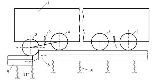
Fig. 1. The
scheme of passage of butt roughness
3.2. Static interaction
For the
static calculation of the rail deflections, a model of a multispan beam on 24
elastic supports is used (23 ties and support, which simulates a connection to
the adjacent rail running through the working overlay). To calculate the rail
rigidity value (ср) its deflection at the
end δр under the action of a single force
is determined, then: ср=1/δр. Taking
into account the connection of the working overlay with the rigidity сн of the
giving and receiving rails, we obtain the rigidity of the rail at the end:
![]() . (1)
. (1)
The main force factors
determining the static deflection of the receiving rail under the first elastic
support are constant in magnitude external
forces Р0. They correspond to the
current number of wheel pairs on the rails attached to the giving rail (Fig. 2)
and have the coordinates ХВj, where j = 1, 2, 3, 4 –
the number of the carriage wheel pair.
On Fig. 2: li (і = 1–23); l24=lр.к.=12.5 m – geometric coordinates of elastic supports; Р0 – loads on the side of the
carriage per wheel; ![]() – spring force applied to the
end of the receiving rail by the giving rail at the end;
hВ4ф –
giving rail deflection at the end of the fourth motion phase of the tram
carriage;
– spring force applied to the
end of the receiving rail by the giving rail at the end;
hВ4ф –
giving rail deflection at the end of the fourth motion phase of the tram
carriage; ![]() ;
; ![]() ,
, ![]() ,
, ![]() , c – the ballast
layer rigidity under the sleeper of the upper structure of the path.
, c – the ballast
layer rigidity under the sleeper of the upper structure of the path.
The
equation of the curved axis of the rails at the fourth motion phase will be
written using the method of initial parameters, including the conditions of
fastening. At the origin of the deflection and the angle of rotation of the
sections of both rails are zero, so we get: (у0 = у0' = 0).
For the
other three phases', there will be a difference only in the number of wheels on
the giving and receiving rails.
For the rear rail is
obtained
 . (2)
. (2)
For the receiving rail
 ; (3)
; (3)
Here J – is inertia moment of the rail
cross-section relative to the neutral axis; Е – elastic modulus of rail
material; ![]() – rail length; Q0, M0 are the transverse force and the bending moment in
the coordinate origin.
– rail length; Q0, M0 are the transverse force and the bending moment in
the coordinate origin. ![]() – reaction force of elastic supports. The main force factors
that determine static deflection of the receiving rail under the first elastic
support (2-3) are the external forces Р0=Р/8 (the load at the side of the
car that falls on one wheel; P is the
weight of the car with respect to its load), constant by their magnitude.
– reaction force of elastic supports. The main force factors
that determine static deflection of the receiving rail under the first elastic
support (2-3) are the external forces Р0=Р/8 (the load at the side of the
car that falls on one wheel; P is the
weight of the car with respect to its load), constant by their magnitude.
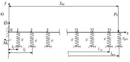
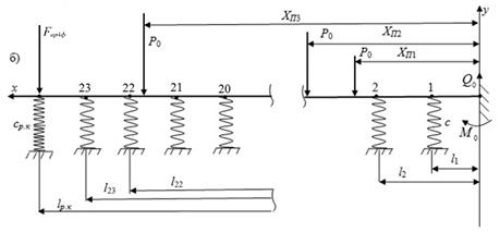
Fig. 2.
The mechanical pattern of calculation of the junction height in the fourth
motion phase: а) rear rail; b) receiving rail
The
current value of the butt roughness height is calculated from the defined
elastic lines of the rear and receiving rails
![]() ,
,
where ![]() ,
, ![]() – deflections of receiving
and rear rails at the ends. Taking into account that the
expressions (2) and (3) in the right part contain summands, which in turn
depend on deflections, the solutions of these equations are performed
numerically.
– deflections of receiving
and rear rails at the ends. Taking into account that the
expressions (2) and (3) in the right part contain summands, which in turn
depend on deflections, the solutions of these equations are performed
numerically.
3.3. Shock interaction
Putting into
consideration the parameters dependence of the shock impulse as well as after the impact
speed of the trolley wheel, passing butt roughness path from the following factors: the joint height of the type “gap
– step up”; carriage loading; design and operational parameters of
the vehicle. Hence, the carriage is presented in the form of a sprung summary
mass on the truck, and it is assumed that when the wheel hits the edge of the
receiving rail, its separation does not occur, as well as its sliding relative
to the rail, which does not contradict the results of the papers [6,17,28]. At
this stage, using the system motion angular momentum theorem [28], the
parameters of the shock impulse are determined, the receiving rail will test in
its shock interaction with the truck wheel. Presented according to the scheme
in Fig. 3 is the shock interaction
of the wheel from first wheel pair of the carriage and the receiving track rail
with consideration for the motion angular momentum theorem of the mechanical
system.
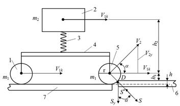
Fig. 3. Shock interaction scheme
Here: 1 – wheel of the corresponding wheel pair of the tram carriage; 2 – structural element that models the reduced mass of the; 3 – elastic suspension of the carriage; 4 – truck frame; 5 – wheel from the first wheel pair of the truck; 6, 7 – the rear and receiving rail of the path; h – joint height; h1, h2 – geometrical coordinates of the mass
centres of the wheels 1, 5 and reduced mass 2 of
the carriage; V1k, V2 – to-the-shock and after-the-shock
velocity of the wheel 5; S, Sy – shock impulses, that the receiving rail do
experience while its shock interaction with wheel 5 from the first wheel pair of the
truck; α – angular coordinate of
the wheel centre of mass 5; m1, m2 – reduced masses of the wheel and the
carriage; r – wheel radius. Here, the shock impulse S* equals
by value to the impulse S. In this setting, it corresponds to
the law of conservation of momentum
![]() ,
(4)
,
(4)
where К1, К2
– to-the-shock and after-the-shock system motion angular momentum relative to the axes, passing along the edge D of the receiving rail 6; S* – external shock impulse, applied to the wheel 5 from the receiving rail; ![]() – shock impulse-momentum
relative to the edge D. In equation (4) the moments of the
amount of motion, taking into account the scheme in Fig. 3, which is
– shock impulse-momentum
relative to the edge D. In equation (4) the moments of the
amount of motion, taking into account the scheme in Fig. 3, which is
![]()
![]() .
.
Taking into the account, that shock impulse S* crosses wheel centre of masses 5, while velocities of the wheel 1 and reduced mass 2 of the carriage equals to V1k and do
not change own direction during
the strike, equation 4 allows to indicate the value after-the-shock
speed:
![]() .
.
One defines a shock impulse
of the mechanical scheme interaction in Fig. 3 with the flat end of the receiving rail in projections
on the vertical axis y, in accordance
with the system motion angular momentum theorem, as (considering V1ky = 0)
![]() ,
(5)
,
(5)
where ![]() . Equation 5 establishes
the dependence of the parameters of the vertical component of the shock pulse
on the mass and radius of the wheel, the speed of its centre of mass, as well
as the height of the butt roughness at this phase of the movement. In this
paper, the dependence (5) is further used to determine after-the-shock vertical
cross-section velocity of the receiving rails at the end. The following
approach is used. Experiencing shock impulse Sy, the flat end of the
rail 6 (Fig. 3) will receive at
. Equation 5 establishes
the dependence of the parameters of the vertical component of the shock pulse
on the mass and radius of the wheel, the speed of its centre of mass, as well
as the height of the butt roughness at this phase of the movement. In this
paper, the dependence (5) is further used to determine after-the-shock vertical
cross-section velocity of the receiving rails at the end. The following
approach is used. Experiencing shock impulse Sy, the flat end of the
rail 6 (Fig. 3) will receive at ![]() (Fig. 2), given that on impact, the
receiving rail bends along the same curve as under the action of a static
concentrated load, under elastic deformation conditions according to (3),
vertical displacement
(Fig. 2), given that on impact, the
receiving rail bends along the same curve as under the action of a static
concentrated load, under elastic deformation conditions according to (3),
vertical displacement
 ,
,
where ![]() – peak value of deflection;
– peak value of deflection; ![]() – deflection of the rail flat end under the action of a single force
– deflection of the rail flat end under the action of a single force ![]() Н when
Н when ![]() ;
; ![]() – joint
height on the i-th carriage
motion phase. It is taken into account that the
joint height of the track is a function of the motion phase. The
velocity of the rail cross-section with the coordinate х will be at time t, in accordance with the Fourier method
of variables separation:
– joint
height on the i-th carriage
motion phase. It is taken into account that the
joint height of the track is a function of the motion phase. The
velocity of the rail cross-section with the coordinate х will be at time t, in accordance with the Fourier method
of variables separation:
 ,
(6)
,
(6)
where ![]() – the change rate of the amplitude with time
– the change rate of the amplitude with time ![]() , that
is, the vertical cross-section velocity of the receiving rail. The obtained
distribution of speed along the length of the rail (6), allows writing the expression for
its momentum (5). This results in an expression for
the vertical component, for the subsequent calculation of the after-the-shock velocity. Momentum
, that
is, the vertical cross-section velocity of the receiving rail. The obtained
distribution of speed along the length of the rail (6), allows writing the expression for
its momentum (5). This results in an expression for
the vertical component, for the subsequent calculation of the after-the-shock velocity. Momentum ![]() of the receiving rail 6 in the projection on the axis
after-the-shock interaction with the wheel 5 we define as
of the receiving rail 6 in the projection on the axis
after-the-shock interaction with the wheel 5 we define as
 ,
,
where ![]() . Thus, including (5) and (6) with
. Thus, including (5) and (6) with ![]() after-the-shock vertical velocity of the rail is
determined as
follows:
after-the-shock vertical velocity of the rail is
determined as
follows:
 . (7)
. (7)
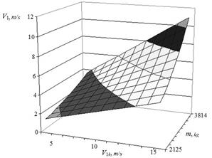
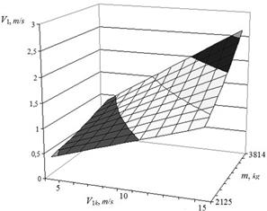
4. INVESTIGATION RESULTS
According to the model proposed, the numerical analysis of the parameters between the shock interaction
of a four-axle vehicle with a rail track in the place of an isolated butt roughness of the “gap”
type is performed on the example of a tram carriage. The calculations were
conducted based on the variation of carriage loading, velocity and reduced to
one of the wheels mass of the carriage according to the defined phases of
motion. Fig. 4-7 show the dependences after the shock velocity ![]() of the receiving rail. Table
1 shows the data of mechanical interaction at the maximum load of the carriage
and the speed of movement tram (15 m/s)
at all phases.
of the receiving rail. Table
1 shows the data of mechanical interaction at the maximum load of the carriage
and the speed of movement tram (15 m/s)
at all phases.
The analysis was carried out according to the
calculation scheme shown in Fig. 2–3. The following design
characteristics of the rail Р-65 and the tram Т-3 [18]: Е = 2.6·1011 N/m2; J = 3573 сm4; ρ = 7.8 кg/m3; F = 82.65 сm2; с = 4.225·105 N/m were
used.
The reduced to one wheel mass of the empty carriage is m = m1+m2 = 2125 кg, while maximum mass (with 193 passengers) of the
loaded one – m = 3814 кg; m1 = 1100 кg. This
corresponds to real operating conditions and design characteristics of the tram
vehicle and rail track.
Tab. 1
Characteristics of
mechanical interaction of four-axle tram and track
|
Characteristic |
Phase 1 |
Phase 2 |
Phase 3 |
Phase 4 |
|
Height of joints [mm] |
3.89 |
1.01 |
1.95 |
0.67 |
|
After-the-shock velocity [m/s] |
10.93 |
4.708 |
8.234 |
2.623 |
|
Fig. 4. Dependence after-the-shock
velocity on the operational factors at the first phase |
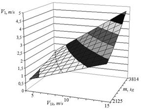
Fig. 5. Dependence after-the-shock
velocity on the operational factors at the second phase |
|
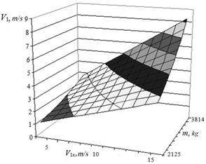
Fig. 6. Dependence after-the-shock
velocity on the operational factors at the third
phase |
Fig. 7. Dependence
after-the-shock velocity on the operational factors at the fourth phase |
5. SUMMARY
The laws analysis shows, for example, that the variation of reduced to the one wheel mass of the tram carriage in the range ![]() кg with design velocity of
кg with design velocity of ![]() m/s leads to a change after the shock
velocity depending on the phases of the tram carriage motion, respectively, in
the ranges V1 = [4.635÷10.93] m/s, V1 = [2.355÷4.708] m/s, V1 = [3.729÷8.234] m/s, V1 = [1.368÷2.623] m/s, that is, to the growth 2.36; 1.99; 2.2; 1.92 times.
m/s leads to a change after the shock
velocity depending on the phases of the tram carriage motion, respectively, in
the ranges V1 = [4.635÷10.93] m/s, V1 = [2.355÷4.708] m/s, V1 = [3.729÷8.234] m/s, V1 = [1.368÷2.623] m/s, that is, to the growth 2.36; 1.99; 2.2; 1.92 times.
One presented the results of numerical calculations of static and shock interaction
parameters on the example of a tram carriage with a rail track at the junction,
which takes into account operational, mechanical and geometric factors using
the proposed models. It defines new regularities of interaction of the
four-axle carriage with a rail track with vehicle passing through the butt
roughness and allows to make improvement of operational parameters and design
characteristics of the carriage and the top structure of a truck by rational
choice and optimisation of parameters.
The results obtained are of significant theoretical importance in
establishing the laws of influence of operational factors, and practically,
they are used in the development of technical solutions to improve the junction
of the track, in determining the modes of operation of tram carriages,
including other four-axis, taking into account the limit values of shock
impulses of interaction. Also, when creating an experimental-theoretical
complex for research, calculations and improvement of the parameters of the
carriage and the upper structure of the track.
References
1.
Aristizabal Mauricio, Jaime L. Barbosa, German R. Betancur, Leonel F.
Castañeda, Bogdan Żółtowski. 2014. “Structural
diagnosis of rail vehicles and method for redesign”. Diagnostyka 15(3): 23-31.
2.
Auersch
L. 2017. „Mitigation of railway induced vibration at
the track, in the transmission path through the soil and at the building”. Procedia Engineering
199: 2312-2317. DOI: 10.1016/j.proeng.2017.09.192Get rights and content.
3.
Cejka Jiri, Martin Telecky. 2019. „Influence of economic and
political factors on the public rail transport”. Komunikacie (Communications - Scientific Letters of the University of
Zilina) 21(2): 13-17. ISSN: 1335-4205.
4.
Czech Piotr. 2011. „Diagnosing of disturbances in the ignition
system by vibroacoustic signals and radial basis function - preliminary
research”. Communications in
Computer and Information Science 239: 110-117. DOI
https://doi.org/10.1007/978-3-642-24660-9_13. Springer, Berlin, Heidelberg.
ISBN: 978-3-642-24659-3. ISSN: 1865-0929. In: Mikulski Jerzy (eds), Modern
transport telematics, 11th International Conference on Transport Systems
Telematics, Katowice Ustron, Poland, October 19-22, 2011.
5.
Czech Piotr. 2012. „Determination of the course of pressure
in an internal combustion engine cylinder with the use of vibration effects and
radial basis function - preliminary research”. Communications in Computer and Information Science 329: 175-182.
DOI https://doi.org/10.1007/978-3-642-34050-5_21. Springer, Berlin, Heidelberg.
ISBN: 978-3-642-34049-9. ISSN: 1865-0929. In: Mikulski Jerzy (eds), Telematics
in the transport environment, 12th International Conference on Transport
Systems Telematics, Katowice Ustron, Poland, October 10-13, 2012.
6.
Даренський
О.М., А.В. Клименко. 2013. „Моделирование взаимодействия пути и подвижного состава при дискретном подрельсовом основании в зоне рельсовых стыков”. Інформаційно-керуючі
системи на
залізничному
транспорті 4: 15-22. [In Ukrainian: Darensky O.M., A.V. Klimenko. ”Modeling of interaction between track and rolling stock at discrete
track base in the zone of rail joints”. Railway information and control systems 4: 15-22].
7.
Darensky
O.M., Klimenko A.V. 2013. „Simulation
of the interaction of the track and rolling stock at a discrete sub-rail base
in the area of rail joints”. Information
and control systems in railway transport 4: 15-22.
8.
Fomin
Oleksij, Juraj Gerlici, Alyona Lovska, Kateryna Kravchenko, Pavlo Prokopenko,
Anna Fomina, Vladimir Hauser. 2019. “Durability determination of the
bearing structure of an open freight wagon body made of round pipes during
its transportation on the railway ferry”. Komunikacie (Communications - Scientific Letters of the University
of Zilina) 21(1): 28-34. ISSN: 1335-4205.
9.
Gu
Sh., X. Yang, Sh. Zhou, S. Liang, Yu Zhou. 2016. „An innovative contact partition model for
wheel/rail normal contact”. Wear 366-367: 38-48. DOI: 10.1016/j.wear.2016.07.001.
10. Homišin J., R. Grega, P.
Kaššay, G. Fedorko, V. Molnár. 2019. “Removal of
systematic failure of belt conveyor drive by reducing vibrations”. Engineering Failure Analysis 99:
192-202. ISSN 1350-6307.
11.
Иванов М.Д., А.А. Пономарев, Б.К. Иеропольский.
1977. Трамвайные
вагоны Т-3. [In Russian: Ivanov M.D., Ponomarev A. A., Ieropolsky B. K. Tram cars T-3]. Moscow:
Transport. 240 p.
12. Jacyna M., J. Merkisz.
“Proecological approach to modelling traffic organization in national
transport system”. Transport
systems of Transport 2(30): 43-56.
13. Jacyna
M., M. Wasiak, K. Lewczuk, G. Karoń. 2017. “Noise and environmental pollution from
transport: decisive problems in developing ecologically efficient transport
systems”. Journal of
Vibroengineering 19: 5639-5655. DOI: doi.org/10.21595/jve.2017.19371.
14. Jin Shi, Defeng Hou.
2017. “Failure analysis for railroad embankment under heavy haul wagon
loads”. Mechanika 23(2):
197-203. ISSN 1392-1207.
15. Khadri Y., S. Tekili, E.
M. Daya, A. Daouadji, B. Merzoug. 2013. “Effects of rail joints and
train's critical speed on the dynamic behaviour of bridges”. Mechanika 19(1): 46-52. ISSN 1392-1207.
16. Krajňák J., J. Homišin,
R. Grega, M. Urbanský, 2016. „The
analysis of the impact of vibrations on noisiness of the mechanical system”. Diagnostyka 17(3): 21-26. ISSN 1641-6414.
17. Лазарян В.А.
1964. Динамика
вагонов.
Устойчивость
движения и
колебания. [In Russian: Lazaryan V.A. 1964. The dynamics of the cars. Stability of movement and fluctuations]. Moscow: Transport. 255 p.
18.
Ling X., H. Xiao, X. Cui. 2018. „Analysis of mechanical properties of
polyurethane-mixed ballast based on energy method”. Construction and
Building Materials 182: 10-19. DOI: 10.1016/j.conbuildmat.2018.06.008.
19. Maláková S. 2017.
„Analysis of gear wheel body influence on gearing stiffness”. Acta Mechanica Slovaca 21(3): 34-39.
ISSN 1335-2393.
20. Meehan P.A., R.D. Batten, P.A. Bellette.
2016.
„The effect of non-uniform train speed
distribution on rail corrugation growth in curves/corners”. Wear 366-367: 27-37. DOI: 10.1016/j.wear.2016.05.009.
21. Michalski R., S. Wierzbicki. 2008.
„An analysis of degradation of vehicles in operation”. Eksploatacja i Niezawodnosc –
Maintenance and Reliability 1: 30-32.
22. Moravec M., G. Ižariková, P.
Liptai, M. Badida, A. Badidová. 2018. „Development of
psychoacoustic model based on the correlation of the subjective and objective
sound quality assessment of automatic washing machines”. Applied Acoustics 140: 178-182.
ISSN 0003-682X. DOI: 10.1016/j.apacoust.2018.05.025.
23.
Prakoso P.D. 2012. „The Basic Concepts of Modelling Railway
Track Systems Using Conventional and Finite Element Methods”. Jurnal Ktilmual dan Aplikasi Teknik
13(1): 18-24. DOI: 10.20527/infotek.v13i1.1816.
24. Pukach P.Ya., I.V. Kuzio, Z.M. Nytrebych,
V.S. Il’kiv. 2018. „Asymptotic
method for investigating resonant regimes of nonlinear bending vibrations of
elastic shaft”. Scientific Bulletin
of National Mining University 1:
68-73.
DOI: 10.29202/nvngu/2018-1/9.
25. Puškár M., M. Kopas. 2018.
„System based on thermal control of the HCCI technology developed for
reduction of the vehicle NOX emissions in order to fulfil the future standard
Euro 7”. Science of the Total
Environment 643: 674-680. ISSN 0048-9697. DOI: 10.1016/j.scitotenv.2018.06.082.
26. Sága M., M. Vaško, P. Kopas,
L. Jakubovičová. 2010 „Identification of the hysteretic material
model parameters and application on energy fatigue curve”. Machine Dynamics Research: 79-87. Warsaw University of Technology.
27. Sturm M., L. Pešík. 2017.
„Determination of a vibrating bowl feeder dynamic model and mechanical
parameters”. Acta Mechanica et
Automatica 11(3): 243-246. ISSN 1898-4088. DOI: 10.1515/ama-2017-0038.
28. Вериго
М.Ф.,
А.Я. Коган. 1986. Взаимодействие
пути и
подвижного
состава. [In Russian: Verigo M.F., A.Ya. Kogan. 1986. Interaction of track and rolling stock]. Moscow: Transport. 559 p.
29. Vinogradov B.V. 2015. „The equivalent number of stress cycles in
view of fatigue calculation of tumbling mill gear”. Scientific Bulletin of National Mining
University 1:
72-76.
30. Wheeler
L.N.,
W.A. Take, N.A. Hoult. 2016. „Measurement of rail deflection on soft
subgrades using DIC”. Proceedings
of the Institution of Civil Engineers. Geotechnical Engineering 169(5): 383-398. DOI: 10.1680/jgeen.15.00171.
31. Zul'ová L., R. Grega, J.
Krajňák. 2017. „Optimization of noisiness of mechanical
system by using a pneumatic tuner during a failure of piston machine”. Engineering
Failure Analysis 79: 845-851. ISSN 1350-6307.
Received 05.11.2019; accepted in revised form 10.01.2020
![]()
Scientific
Journal of Silesian University of Technology. Series Transport is licensed
under a Creative Commons Attribution 4.0 International License