Article
citation information:
Mańka, A., Hełka, A.,
Ćwiek, J. Influence of copper content on pantograph contact strip material on
maximum temperature of railroad wire. Scientific
Journal of Silesian University of Technology. Series Transport. 2020, 106, 97-105. ISSN: 0209-3324. DOI: https://doi.org/10.20858/sjsutst.2020.106.8.
Adam MAŃKA[1], Andrzej HEŁKA[2], Janusz ĆWIEK[3]
INFLUENCE
OF COPPER CONTENT ON PANTOGRAPH CONTACT STRIP MATERIAL ON MAXIMUM TEMPERATURE
OF RAILROAD WIRE
Summary. This article presents the results of studies on the
impact of the percentage of copper in the carbon composite of the railway
pantograph contact strips on the maximum temperatures of the contact wire of
the overhead contact line. The tests were carried out in accordance with the
requirements of standards [7, 9] and TSI [4]. The obtained relationship allows
for an initial assessment of the introduced materials due to the contact wire
heating criterion based on the copper content of the carbon composite, which
greatly facilitates the design process and the initial assessment of the
pantograph slides performance. This publication also indicates the minimum
value of the percentage of copper at which the standard requirements [7] for
railroad wire heating are still met.
Keywords: pantograph contact
strip material, carbon strips, composite material, railway pantograph, railroad
wire, maximum temperature of railroad wire
1. INTRODUCTION
The railway pantograph contact strip is an element of traction vehicles
that cooperates with railroad wire during operation. The durability,
reliability and safety of the pantograph and, consequently, the entire railway
vehicle depend on its performance. The contact strip and contact wire used for
decades were technically made of pure copper. Graphite grease was used for
proper cooperation and reduction of wear of this friction pair. As technology
progressed, new materials were developed that enabled the withdrawal of
copper-based contact strips in favour of copper-based carbon composites. This
allows:
- longer service life of
carbon strips at a comparable cost,
- longer life of contact
wires, which reduces the overall cost of network maintenance,
- no need to sinter strips
with contact wires (carbon does not react with copper),
- no need to lubricate the
contact surface of the strip-contact wire.
The listed advantages of the introduced contact strips, including the
reduced adverse impact on the environment (reduction of copper consumption
products and the lack of the use of lubricants) have contributed to the introduction
of the obligatory use of composite contact strips in rail transport throughout
the European Union.
In 2011, the Polish
railway lines introduced the obligation to apply pantographs fitted with
contact strips made of carbon composite. These strips have replaced the copper
ones that were used for many years. This change resulted from the need for the
Polish railways to match the requirements of the Technical Specifications for
Interoperability [4]. This provision forced the carriers to install in their
pantographs composite materials that previously had to undergo specific test
procedures [7, 9], material and thermal testing among others.
In professional literature, many researchers take up the topic related
to the analysis of pantograph dynamic cooperation with the overhead contact
line [1, 8, 13]. The authors define mathematical models describing the
interaction between the pantograph and the overhead contact line, including for
the purposes of pantograph diagnostics [1, 8]. They also examine the impact of
a number of parameters on the intensity of the contact wire wear [12]. There
are also works related to thermal phenomena [10], however, they are focused
mainly on testing the contact wire temperature during operation.
It is important, however, that due to the use of overhead contact lines
in the EU with different rated voltages, that is, from 3 kV to 25 kV, and there
are significantly different requirements for its electrical conductivity. For
instance, assuming a constant power demand value for a traction vehicle, for
example, 5 kW as for a Dragon locomotive, it is simplified that this power can
be obtained at 3 KV supply voltage at 1667 A or 200 A at 25 kV. The presented
extreme current values of 200 A and 1667 A also have their effects in the heating
of the elements through which the electric current flows.
According to Joule–Lenz law, which states that the power of
heating generated by an electrical conductor is proportional to the product of
its resistance and the square of the current:
![]() (1)
(1)
where:
Q [W] – power of
heating generated by an electrical conductor,
R [Ω] –
resistance,
I [A] – current,
t [s] – current
flow time.
Therefore, it can be seen that the obvious disadvantage of using a
relatively low voltage overhead contact line generates very high values of the
flowing current I, which in consequence forces the use of conductors with a
very low resistance R. This applies in particular to the contact strip. The
limitation associated with heat release is important both from the viewpoint of
minimising energy losses and the impact of heat on mating elements. In the case
of copper, an increase in temperature above approx. 200°C causes its
recrystallization and a significant deterioration in its performance, which is
unacceptable for railroad wire. Therefore, the criterion of the amount of heat
generated in the interface between the contact strip and the overhead contact
line is particularly important for rail transport, and the need to verify it is
also found in normative requirements [7, 9].
From the above considerations, it is clear that not all contact strips
that work properly in pantographs operated on 25 kV networks can be used on 3
kV networks. In practice, based on many years of research experience of the
authors, it is found that hardly any material used for contact strips meets all
normative requirements related to current carrying capacity. The basic feature
that affects the applicability of a given contact strip is its specific
conductivity, which results directly from the copper content of the carbon
composite. Based on previous experience in testing the compliance of materials
for contact strips, the authors first took into account the results of testing
the percentage of metals and then performed tests on the thermal resistance of
the contact wire, as these tests were the most demanding and indicated the
desirability of performing further tests provided for in the standard [7].
It can therefore be assumed that it is possible to determine the value
of the percentage of copper that will ensure that the maximum temperature
requirement is met when trying to heat with electricity.
2. RESEARCH METHODOLOGY
PN-K-91001: 1997 on page 12 defines the requirements of 2.15.3. “Contact
wire temperature increase”, which posits that the maximum contact wire
temperature increase over the design ambient temperature, that is, 40°C,
cannot be greater than 80°C. This gives a maximum contact wire temperature
of 120 °C. Tested system: contact strip – contact wire, should be
loaded with the maximum current received from the contact system during the
current, that is, 200 A within 30 min.
The test stand was made in accordance with the normative requirements
presented above, with the provision that the wire was used without significant
wear and tear. Stand 1 Fig. 1 is equipped with a current circuit with one
conductive type Djp100 made of copper in CuETP grade with the required current
value of 200 A. The current value was measured with an indicator ammeter with
an accuracy of ± 5 A and a clamp meter ammeter type CM-9930 from Lutron
with serial number 04011 and measurement uncertainty ± 2% A.
During
the tests, pressure 102 N within the normative range of ![]() N was
applied. The contact wire temperature was measured by placing thermocouples in
the contact wire slots located above the contact strips according to the
diagram in Figure 2.
N was
applied. The contact wire temperature was measured by placing thermocouples in
the contact wire slots located above the contact strips according to the
diagram in Figure 2.
Materials for contact strips being
the subject of tests for placing in service in Poland that is operated at the
rated voltage of the traction network 3 kV were used for the tests. These
materials were given letter markings in the order of the smallest percentage of
copper in the carbon composite. Due to similar results obtained for a group of
materials with a copper content in the range of 30%, the mean values from 3
materials with a share of 29.3; 31.2 and 31.7% Cu were used for further
development.
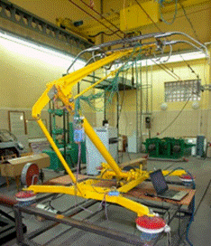
Fig. 1. Laboratory stand
for pantograph and contact strip material testing
![]()
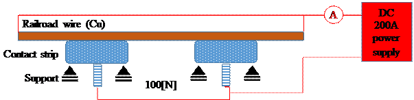
Fig. 2. Diagram of the measuring system
Tab. 1
The percentage of copper in the carbon-copper
composite
|
Material designation |
Copper percentage in composite [%] |
Carbon percentage in composite [%] |
Binder percentage
in composite [%] |
|
A |
0,2 |
94,5 |
5,3 |
|
B |
20,1 |
76,4 |
3,5 |
|
C |
30,7 |
63,5 |
4,8 |
|
D |
40,4 |
48,6 |
11,0 |
It should be noted that, according to the standard [2], the weight of
metals may not exceed 40% of the weight of the overlay material.
A material with a copper percentage of 40.4% was not taken for further
analysis due to a much larger proportion of binders, that is, 11.0%, which
significantly affected the deterioration of the thermal and electrical
properties of the contact strip material. At the same time, exceeding the
threshold of 40% discriminates against this material from further normative
studies.
Importantly, according to the authors, the mandatory examination of the
content of the inclusions of metals required by the standard [7] can also be an
indication for the initial determination of the thermal resistance of the
material to the pantograph contact strips.
3. RESULTS AND
DISCUSSION
As a result of the set current load
in the contact strip – contact wire system, and due to the contact wire
temperature measurement, it was possible to determine in the first minutes of
the test whether the material meets the required condition of not exceeding the
temperature of 120°C. However, the tests were conducted for a period of 30
min set in the standard. The obtained results are presented in Table 2.
Tab. 2
Summary of final temperatures (30 min) of contact wire
for various copper percentages
in the carbon composite of contact strips
|
Material designation |
Copper percentage in composite [%] |
Average contact wire temperature [oC] |
|
A |
0,2 |
230,7 |
|
B |
20,1 |
138,4 |
|
C |
30,7 |
111,7 |
It should be noted that material A
(material used in the 15 kV network) was tested last and as expected, material
with such low copper content does not meet the requirements of the standard [7].
It should also be noted that for material A, already in the 2nd minute of the
test, the contact wire temperature exceeded the permissible value, that is
120°C. In addition, as bench tests showed, the use of such an overlay in
operating conditions would recrystallize the contact wire copper after approx.
9 min of co-operation at standstill, that is, damage to its physical properties
after exceeding 200°C – Fig. 3.
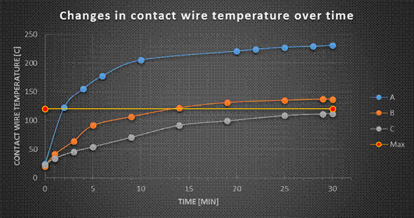
Fig. 3. Summary of test results of the influence of the
percentage of copper strip on the contact
wire temperature (heating 200 A for 30 min)
From the waveforms of temperature
changes presented in Figs. 3 and 4 during the current flow 200 A corresponding
to the values taken by the traction vehicle with the heating switched on, it
can be seen that the material A and B does not meet the heating temperature
criterion, that is 120°C (assuming the initial design temperature of
40°C).
To enable determination of the
minimum value of the percentage of copper above which it is possible to meet
the normative requirements for contact wire heating, the obtained results are
shown in Fig. 4.
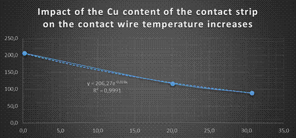
Fig. 4. Summary of contact wire temperature increase values for
various materials of the contact strip relative to the ambient temperature
of 20°C (heating 200 A for 30 min)
From the approximation equation for
the exponential function of the relationship between the percentage of copper
in the contact strip and the contact wire temperature, it follows that the
maximum wire temperature will be 120°C, that is, the increase will be
100°C for a percentage of copper of 26%. Below this value, the maximum
contact wire criterion is most likely not met.
The obtained relationship between
the percentage of copper and the increase in contact wire temperature (at an
ambient temperature of 20°C can be described by the relationship (2).
![]() (2)
(2)
where:
ΔTc [oC]
– contact wire temperature increment,
C [%] – the
percentage of copper in the composite.
The above relationships were
obtained for composites in which, apart from carbon and copper, no more than
about 5% of the binder was used as the binder. It should be noted that making a
composite with a binder of 11% significantly worsens its electrical and thermal
properties even if the percentage of copper is within the limit value. The
final temperature of 103°C was obtained for this material (D).
The graph also shows that the
carbon composite alone without copper with the addition of binder up to approx.
5% will achieve a temperature increase of 206°C or 226°C, which causes
damage to the contact wire (its recrystallization) in less than 9 min after
starting the traction vehicle parking.
At the same time, based on this
relationship, it can also be pointed out that when making a 100% copper contact
strip, the contact wire temperature increase will be about 12°C. Indicated
in standard [7], the maximum value of the 40% copper percentage should cause a
temperature increase of 67.5°C, which is to 87.5°C.
The thermogram (Fig. 5) shows the
temperature distribution in the contact zone of the contact wire with contact
strips.
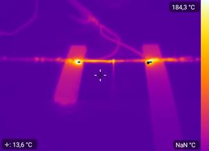
Fig. 5. Thermogram of an example contact point of contact wire
and contact strip
Regardless of the demonstrated
impact of the percentage of copper in the carbon overlay, it should be noted
that while for networks with a supply voltage of 3 kV, it is particularly
important to note the significance of such testing for the use of sliding
overlays on networks with higher voltages, where current values are much lower.
It is expedient to determine the normative values of current loads for vehicles
used on networks with higher nominal voltages.
4. CONCLUSIONS
The research carried out on the impact of the percentage of copper in
the carbon composite of the rail pantograph contact strips on the maximum
contact wire temperatures of the railroad contact line showed that the increase
in copper content in the contact strip material causes a reduction in the
contact wire temperature. The study of the effect of current-carrying capacity
on the contact wire temperature was the most common reason discriminating a
given material for use in the Polish railroad contact line, therefore, the
authors attempted to determine the relationship between copper content and
contact wire temperature to facilitate the preliminary assessment of the
operational suitability of the tested contact strip materials.
Based on the conducted research, the following conclusions can be drawn:
- it is possible to estimate the contact wire
temperature based on the knowledge of the percentage of copper in the carbon
composite as observed in the presented relationship (2), assuming that the percentage
of binder does not exceed approx. 5.3%,
- a high percentage of binder material (adhesive) in the
composite negatively affects its electrical and thermal properties. In
particular, for material with 11% binder and 40% Cu, the permissible contact
wire temperature was exceeded and amounted to 128°C,
- material A operated on 15 kV network did not meet the
requirements for 3 kV network. At the same time, it should be noted that using
such material, it is possible to “overheat” the contact wire,
that is, exceeding the recrystallization temperature of 200°C after approx.
9 out of 30 min of receiving power when the vehicle is stationary.
The authors of the publication see the need to continue the presented
research and extend it to include the impact of the percentage of carbon
composite binders (adhesives) and to determine the impact of contact wire heat
load on its strength, electrical and thermal properties.
References
1.
Alberto A., J. Benet, E. Arias, D. Cebrian, T. Rojo, F. Cuartero. 2008. „A high performance tool for
the simulation of the dynamic pantograph – catenary interaction”. Mathematics and Computers in Simulation 3(79): 652-667.
2.
Benet J., N. Cuartero, F. Cuartero, T. Rojo, P. Tendero,
E. Arias. 2013. „An advanced 3D-model for the
study and simulation of the pantograph catenary system”. Transportation Research Part C 36: 138-156.
3.
Bucca G., A. Collina. 2009. „A procedure for the wear
prediction of collector strip and contact wire in pantograph – catenary system”. Wear 266: 46-59.
4.
Commission Regulation (EU) No 1301/2014 of 18
November 2014 on the technical specifications for interoperability relating to
the ‘energy’ subsystem of the rail system in the Union Text with
EEA relevance.
5.
Ding T., G.X. Chen, J. Bu, W.H. Zhang. 2011. „Effect of temperature and arc
discharge on friction and wear behaviours of carbon strip/copper contact wire
in pantograph – catenary systems”. Wear 271: 1629-1636.
6.
Ding T., G.X. Chen, Y.M. Li, H.J. Yang, Q.D. He. 2014. „Arc erosive characteristics of a carbon strip
sliding against a copper contact wire in a high-speed electrified railway”. Tribology International 79: 8-15.
7.
EN 50405: 2016 Railway applications -
Current collection systems – Pantographs, testing methods for carbon
contact strips.
8.
Judek S., M. Michna, M. Mizan, K. Karwowski, A.
Wilk, P. Kaczmarek. 2016. „Mathematical modeling of the
overhead contact line for the purpose of diagnostics of pantographs”. Elektrotechnika 113(1-E): 79-89.
9.
PN-K-91001:1997 Electric traction vehicles, Current
collectors, Requirements and test methods, PKN December 1997.
10. Theune N., T. Bosselmann, J. Kaiser,
M. Willsch, H. Hertsch, R. Puschmann. 2010. „Online temperature monitoring of overhead contact
line at the new German high-speed rail line Cologne-Rhine/Main”. WIT Transactions on State of the Art in Science and Engineering 39. WIT Press. ISSN 1755-8336. DOI: 10.2495/978-1-84564-498-7/09.
11. Trans-European-Conventional
Rail System Subsystem Rolling Stock Tsi “Lokomotives And Passenger
Rst” IU-RST-03-08-2009-TSI draft Version 3.0 Date: 3/08/2009.
12. Shing A.W.C., P. Wong. 2008. „Wear of pantograph collector
strips”. Proceedings of the Institution of Mechanical Engineers Part F Journal
of Rail and Rapid Transit 222(2): 169-176. DOI: 10.1243/09544097JRRT156.
13. Sitarz M., A. Hełka, A. Mańka, A. Adamiec.
2013. „Testing of railway pantograph”. Archives
of Transport 25-26(1-2): 85-95. ISSN 0866-9546.
Received 26.10.2019; accepted in revised form 04.01.2020
![]()
Scientific
Journal of Silesian University of Technology. Series Transport is licensed
under a Creative Commons Attribution 4.0 International License