Article
citation information:
Konowrocki, R. Modelling of
dynamic aspects of operation in railway vehicle traction drive system including
the electromechanical coupling. Scientific
Journal of Silesian University of Technology. Series Transport. 2019, 105, 101-111. ISSN: 0209-3324. DOI: https://doi.org/10.20858/sjsutst.2019.105.9.
Robert
KONOWROCKI[1]
MODELLING
OF DYNAMIC ASPECTS OF OPERATION IN RAILWAY VEHICLE TRACTION DRIVE SYSTEM
INCLUDING THE ELECTROMECHANICAL COUPLING
Summary. In this paper, the influence of electromechanical
interaction in an electric motor on the railway vehicle driving system dynamics
was investigated. This is the train driven by DC. In particular, there is
considered influence of electromagnetic field between a rotor and stator on
excitation of resonant torsional vibrations of the drive system. Conclusions
drawn from the computational results can be very useful during the design phase
of these devices as well as helpful for their users during regular maintenance.
Keywords: railway drive system,
electromechanical coupling, numerical analysis, electric motor, torsion
vibration, railway vehicle operation
1. INTRODUCTION
Torsional
vibrations occur in every drive train. For a simple drive train, which consists
of an electrical motor, flexible shaft and a load, its system has two basic
torsional vibration modes, the rigid-body mode and the first elastic mode. The
knowledge about the torsional vibrations in drive transmission systems of
railway vehicles is of great importance in the field of dynamics of mechanical
systems [3,4,7,8,10,14,15,19]. Components of driving systems are not fully rigid, it is common
to have fluctuation of torques in different work phases leading to shaft and
wheelset torsional vibration [5,11]. For the
reliability and security of the drive system of railway vehicles driven by
electric motors, the electromagnetic output traction force and torques should
drive stably. Otherwise the shaft train vibration caused by motor torque ripple
will affect the fatigue life of the drive components and the operation security
of the driven railway vehicles [2,9,18]. Generally,
railway drive systems can be divided into electrical and mechanical parts, for
this reason, the influence of the electric motor should also be taken into account
in the dynamic analysis of the drive.
In practice, various
types of motors for traction applications are used. Among which are: DC shunt
motor, compound motors, separately excited motors, AC series motor, 3-phase
induction motor. The selection of motors depends on a variety of factors like
the type of traction, type of supply, mainline/suburban trains, etc. The motor
should provide high starting torque, which is very essential because in trains
there are many compartments full of passengers or goods, so it requires high
torque during initial start-up and traction operation. In our case, we will
deal with the railway traction system driven by a DC motor. In this paper, the
effect of electromechanical coupling in the electric motor on torsion vibration
of the railway drive system was analysed. For this
analysis, the method presented therein [2] was applied. In the considered
model, the magnetic field interaction between the stator and the rotor of the
DC motor was considered. Using the energy balance of the natural modes of
oscillations for the model of the railway traction drive are obtained
expressions for determining the influence of electromagnetic parameters of the
electric motor (stiffness and damping of electromagnetic field) on its
stability in relation to the torsion vibration of the railway drivelines.
2.
THE DRIVETRAIN UNDER INVESTIGATION
For analysis of
torsional vibrations in a dynamic mutual coupling between the wheelset and the
electric motor, a possibly realistic and reliable electromechanical model of
the railway drivetrain was applied. In the study, electric locomotives with the
fully sprung wheelset drive were used. In this drive system, the DC traction
motor is a drive unit. The motor shaft is connected to the pinion wheel of the
gearbox by an elastic coupling. The gearbox provides the transmission of the
torque to the wheel axle thus reducing the angular speed. The gear wheel is
mounted on a hollow shaft which is coupled to the wheel axle by an elastic
coupling. Motor and gearbox housing are connected rigidly to each other and are
suspended in the bogie frame by rubber silent blocs (Fig. 1).
3. MATHEMATICAL MODEL OF THE RAILWAY TRACTION DRIVE
SYSTEM
The kinematic diagram of the considered railway traction drive system
model with a DC motor is depicted in Figure 2. Output shaft of the electric
motor is coupled to the hollow shaft connected with the wheelset. The
electrical drivetrain shown in Figure 1 can be reduced by assuming infinite
gear tooth stiffness and assuming the wheel shaft coupling as a single spring.
A simple model of this drive is shown in Figure 2. The output driving torque
from the electric motor is transmitted via coupling to the hollow shaft, which
surrounds the wheelset axle. On the opposite end of the hollow shaft, the
torque is transmitted by means of a flexible claw coupling to the disc-wheel.
On the basis of the data on the cross-section area as well as the length of the
hollow shaft and geometry of the wheelset, stiffness of these assembled
elements was determined. In the considered model, the toothed gear was omitted,
treating it as an element with several times more stiffness than the hollow
shaft.
Fig.
1. Railway drive system with hollow shaft
transmitted torque [16]
Fig. 2. Scheme of model of railway drive
The equation of motion
of the mechanical model shown in Fig 2 can be described in matrix form
|
|
(1) |
where I denotes the mass matrix containing mass moments of inertia of
rotating elements of the drive system, the matrixes,
Ce-m, Ccoupl, Cwheelset, Kcoupled , Ke-m and Kwheelset represent the torsional damping and stiffness properties of electric
motor magnetic field, rotor shaft, the hollow shaft and the wheelset,
respectively. Vector Tmotor contains the electromagnetic torque generated by the electric motor
described in equation (1) of the paper and vector Mcreep contains the traction torque generated by
longitudinal tangential loads Tcreep_i in the wheel-rail zones
acting on wheel radius ri.
The electromagnetic torque of DC motor Tmotor,
the stiffness and damping generated by the electromagnetic field between stator
and rotor of the motor are defined by equation 2-4, according to Riven [1].
|
|
(2) |
|
|
(3) (4) |
where: ![]() . Parameters kv, R, L, U,
IM, ω0, τe, p and
. Parameters kv, R, L, U,
IM, ω0, τe, p and ![]() are respectively constant (ratio of the voltage generated by the motor
to the speed), electrical resistance and inductance of the motor windings, the
power supply voltage, mass moments of inertia of rotor, no-load speed of the
motor, electromagnetic time constants, slope of torque Tmotor versus
slippage characteristic (Fig. 3), angular speed of rotor. ke-m(ω) and ce-m(ω) are respectively the stiffness and damping
coefficients associated with the electromagnetic field. These parameters in the
considered model are represented as the viscoelastic electromagnetic clamping
of the motor rotor with the immovable stator (Fig. 2). The angular position of the rotor of the DC motor is
represented by j1 and the
angular positions of the wheels of the wheelset are described by j2 and j3, respectively. Ikl, Ikr
are the mass moment of inertia of the left and right wheel of the wheelset.
are respectively constant (ratio of the voltage generated by the motor
to the speed), electrical resistance and inductance of the motor windings, the
power supply voltage, mass moments of inertia of rotor, no-load speed of the
motor, electromagnetic time constants, slope of torque Tmotor versus
slippage characteristic (Fig. 3), angular speed of rotor. ke-m(ω) and ce-m(ω) are respectively the stiffness and damping
coefficients associated with the electromagnetic field. These parameters in the
considered model are represented as the viscoelastic electromagnetic clamping
of the motor rotor with the immovable stator (Fig. 2). The angular position of the rotor of the DC motor is
represented by j1 and the
angular positions of the wheels of the wheelset are described by j2 and j3, respectively. Ikl, Ikr
are the mass moment of inertia of the left and right wheel of the wheelset.
Depending on the adopted various maintenance,
operation and weather conditions, an adhesion in wheel-rail contact zone
characteristic can take into consideration these various forms [17]. The
adhesion curve applied for the carried out investigations was plotted in Fig. 3
(left). Presented in the figure are an adhesion
and traction characteristic and instantaneous point equilibrium between them. Here, p
and ηi
meaning respectively, the slope coefficients of the traction
characteristics (green curve) and adhesion characteristics (red curve) in the
vicinity of the temporary equilibrium point. Example graphs of the driving/electric
torque moment Tmotor
and the resistance torque MTcreep caused by the coefficient of wheel-rail
adhesion are shown in Fig 4a and b. These diagrams
illustrate the stability of the drive wheel set depending on which of the Tmotor
or MTcreep
torque is larger. Such an appearance has an effect on the torsional vibration
of the wheelset.
The matrix form of traction drive
model represented by a three-mass rotating system (Fig. 2) can be
described by a system of differential equations (5).
|
|
,
(5) |
where k2 and c2 are the stiffness
and damping characteristics of the wheelset structure. ηkp and ηkl
coefficients
of slope of the adhesion characteristics in the wheel-rail contact area of both
wheels. The
electromagnetic time constant of the windings ![]() describes the delay of reduce in
the current in comparison to the initial value when the voltage is switched at
the terminals of DC motor. It is actually the stall current because as soon as
the motor starts to rotate, it generates a back electromotive force (EMF) to oppose the
applied voltage, which reduces the actual current flowing. Therefore, for rapid
acceleration of a motor, a very high voltage and steady feed of the motor with
a constant current circuit is needed.
describes the delay of reduce in
the current in comparison to the initial value when the voltage is switched at
the terminals of DC motor. It is actually the stall current because as soon as
the motor starts to rotate, it generates a back electromotive force (EMF) to oppose the
applied voltage, which reduces the actual current flowing. Therefore, for rapid
acceleration of a motor, a very high voltage and steady feed of the motor with
a constant current circuit is needed.
Fig.
3. Equilibrium mode of adhesion and traction characteristic
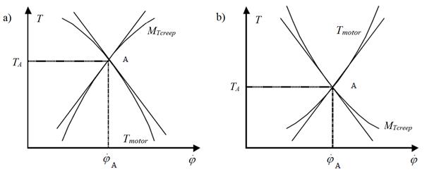
Fig.
4. Example of stability, a) and unstability, b) conditions of the adhesion
and traction characteristic [6]
In the considered case,
we assume that the conditions of adhesion in wheel-rail zones of both wheels of
wheelset are the same. Therefore, we can simplify the considered system by introducing a
relationship that ηkp= ηkl= η (Fig. 3). If the system is on the boundary of
stability, the condition of energy balance implies that the average power
supplied to the system in the process of self-excited oscillations with i-th natural frequency is equal to the average power
dissipated in the process of self-oscillations, a similar approach was used in
this paper [12]. Assuming that the generalised coordinates of the model vary
harmonically, we define the average for the period of power supplied into the
system in the process of self-excited oscillations with natural frequency ωi
|
|
(6) |

where Ti describes the period of
oscillation with a natural frequency of this system, expressed relation ![]() . In
the considered case, the power dissipated due to mechanical damping of the
railway drive elements
. In
the considered case, the power dissipated due to mechanical damping of the
railway drive elements![]() can be determined by equation 7
can be determined by equation 7
|
|
(7) |
In order to estimate the
average over power Ee-mech
consumed in the electromechanically interaction in motor, the first equation of
system (5) was analysed. In (5), Tmotor stands for the
dissipative torque that reflects the electromechanical coupling in the electric
motor. Accordingly, to [12] the average power Ee-mech computed for the oscillation
period can be defined as follows:
|
|
(8) |
Introducing the
assumption Tmotor=Tmotor
sin(ωit+ψi), we can estimate the
modulus of torque Tmotor, and solve the first equation of system
(5) by employing the method of complex amplitudes, described in detail in this
paper [12]. This approach takes into account both the amplitude-frequency
characteristic of the inertial link W(ωi)
and phase angle ψi
between the velocity and torque of the motor. Such a link in the first order equation
(5) can
influence the phase angle between the input and output in the range ψ=0-π/2. Note that a small value of the dissipation phase angle ψ does not significantly affect the
frequency of the oscillations. Nevertheless, in calculating the power
dissipation, the phase angle must be taken into account. As a result, equation
(8) can be represented by
|
|
(9) |

where pequili_i is the
dynamic slope coefficient of the traction characteristics of motor that depends
on the electrical machine’s time constant τe and frequency of the vibration of the rotor ωi.
The
total average power Ed
dissipated in the motor during the oscillations can be computed using:
|
|
(10) |
The condition at which
the input energy generated by self-excited vibration and the dissipated energy
are equal Eself =Ed, and the system is on the
stability boundary (Fig. 4a) takes the following
form:
|
|
(11) |
Using the values of the
coefficients of forms of vibration that correspond to the boundary damping ![]() for the oscillations with
the natural frequency ωi, the equation (11) can be written by:
for the oscillations with
the natural frequency ωi, the equation (11) can be written by:
|
|
(12) |
The natural frequencies
of oscillations in the considered drive can be computed by using the equation
|
|
(13) |
where the coefficients of the
natural forms are as follows:
|
|
(14) |

In the case of the
considered traction drive model, the coefficients of natural forms (14) depend
on the inertial parameters of drive IM,
Ikp and stiffness
coefficients k1,
k2,
ke-m.
For the assumption that
the damping in the wheelset is a small number and can be neglected (c2=0),
the equation (12) can be written as follows:
|
|
(15) |

The expression (15) for the
low-frequency mode of vibration becomes:
|
|
(16) |
Furthermore, the expression (15)
for the high-frequency mode of vibration can be written as:
|
|
(17) |
In the numerical study,
we considered a railway drivetrain system with torsionally
flexible hollow shaft. The wheelset of the total weight of 1700 kg and the
loads for the wheels of Q1=Q2=42 kN are assumed. The wheelset is
driven by the DC motor by means of the hollow shaft with the torsional
stiffness and damping coefficient k1=3000 kNm and c1=100 Ns/m, respectively. It is assumed that the radius of
the wheelset axle and the length of the axle is respectively equal to 0.07 m
and 1.6 m. The torsional stiffness of this axis was determined as k2=14e7 Nm/rad. The remaining
parameters used in the simulations are summarised in
Table 1.
Tab. 1
Simulation base parameters
|
η, kNms |
ce-m, Ns/m |
c2, Ns/m |
p, kNms |
IM, kgm2 |
Ikl = Ikr, kgm2 |
τe, s |
|
10 |
4 |
50 |
20 |
2.1 |
78 |
0.01 |
Applying equations 13
and 14 for the considered railway drive, we can demonstrate the natural
frequencies of the system as functions of the stiffness of the wheelset k2
and stiffness of the connection between the electric drive and wheelset k1
(Fig. 5). The influence of skipping of the stiffness coefficient kem
associated with the electromagnetic field of electric motor on the dynamics of
the considered drive system is marked on the charts (Fig. 5) by kem=0.
Using equations 15-17
obtained from the analysis of the railway drivetrain’s model are plotted
the regions of existence of torsional self-vibration by the consideration and
non-consideration of the damping coefficient associated with the
electromagnetic field of electric motor (cem![]() 0 and cem=0) (Fig. 6). The chart
demonstrates four areas I, II, III, IV corresponding to different types of
vibrations.
0 and cem=0) (Fig. 6). The chart
demonstrates four areas I, II, III, IV corresponding to different types of
vibrations.
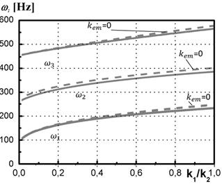
Fig.
5. The natural frequencies of existence of torsion
vibration in the traction drive
as a
function of the relationship k1/k2
Comparing the obtained
results with those presented in the paper [12], a qualitative match can be
observed. Analysing the waveforms presented in Figure 5, it can be concluded that
if the damping coefficient c2 in the driveline takes value located below the
line ![]() , then the system is sensitive to low frequency torsional vibrations. On
the other hand, if the value of c2 is within the region located below the line
, then the system is sensitive to low frequency torsional vibrations. On
the other hand, if the value of c2 is within the region located below the line ![]() , then the high self-excited torsional vibrations can be observed.
, then the high self-excited torsional vibrations can be observed.
Summarising the results,
it can be concluded that in the region I, only the high-frequency self-excited
vibration may occur. The value of damping c2 in the region II
can induce the low-frequency self-excited torsional vibrations. In region III,
the self-excited torsional vibrations cannot occur. Finally, in region IV, both
types of vibrations mentioned above may be induced.
It is worth mentioning
that if we omit the damping cem generated by the electromagnetic field in the
model of DC motor, then the region IV expands its area. In the same time, the
area of the region I shrinks.
Fig. 6. The regions of
low-, high- and self-
excited torsional vibrations
in the considered driveline
4. SUMMARY AND CONCLUSION
The obtained results
demonstrated that the electromagnetic transient processes generated in the
electric motor should be taken into account when analysing
the stability of the system. The knowledge about the stability of drive
transmission systems of railway vehicles is of great importance in the field of
dynamics and material fatigue of the drive systems component.
In this paper, a dynamic
interaction between the torsionally vibrating railway
wheelset and rotor of driving DC motor was investigated. Based on the method of
the energy balance of the natural modes as described in detail in this paper [12],
the analysis on the oscillations of a railway driveline takes into account the
influence of electromagnetic parameters on its stability in relation to
self-excited torsional vibration generated by adhesion in the wheel-rail zone.
From the viewpoint of
the transient and steady state dynamic responses, particular attention was
focused on the influence of the dynamic properties of the mechanical system as
well as selected electromagnetic parameters of the electric motor. In the analysed case, special attention was focused on the
stiffness and damping coefficients associated with the electromagnetic field of
the DC motor. The less the mechanical damping in the driven system, the greater
the possibility of severe torsional resonances, particularly when in such a
drive train, a semi-elastic connection as hollow shaft with a linear
characteristic is used. The obtained results can serve for the design of the
driven systems and be helpful for their users during regular maintenance.
Reference
1.
Amezquita-Brooks
Luis, Eduardo Liceaga-Castro, Jesus Liceaga-Castro. 2014. “Novel design
model for the stator currents subsystem of induction motors”. Applied Mathematical Modelling 38(23): 5623-5634. ISSN 0307-904X.
2.
Bogacz Roman, Kurt Frischmuth. 2016.
“On dynamic effects of
wheel–rail interaction in the case of Polygonalisation”. Mechanical Systems and Signal Processing 79: 166-173. ISSN: 0888-3270. DOI:
10.1016/j.ymssp.2016.03.001.
3.
Czech Piotr. 2012.
„Determination of the course of pressure in an internal combustion engine
cylinder with the use of vibration effects and radial basis function -
preliminary research”. Communications in Computer and Information
Science 329: 175-182. DOI:
https://doi.org/10.1007/978-3-642-34050-5_21. Springer, Berlin, Heidelberg.
ISBN: 978-3-642-34049-9. ISSN: 1865-0929. In: Mikulski Jerzy (eds), Telematics in the Transport Environment,
12th International Conference on Transport Systems Telematics, Katowice Ustron, Poland, October
10-13, 2012.
4.
Czech Piotr. 2011. „Diagnosing of disturbances in the ignition
system by vibroacoustic signals and radial basis
function - preliminary research”. Communications in Computer and Information Science 239: 110-117. DOI:
https://doi.org/10.1007/978-3-642-24660-9_13. Springer, Berlin, Heidelberg.
ISBN: 978-3-642-24659-3. ISSN: 1865-0929. In: Mikulski Jerzy (eds), Modern
Transport Telematics, 11th International Conference on Transport Systems
Telematics, Katowice Ustron, Poland, October 19-22, 2011.
5.
Duda Sławomir. 2014.
“Numerical simulations of the wheel-rail traction forces using the
electromechanical model of an electric locomotive”. Journal Theoretical and Applied Mechanics 52(2): 395-404.
6.
Eugene
I. Rivin. 1999. Stiffness and
damping in mechanical design, CRC Press, pages 528. DOI:10.1115/1.802939.
7.
Haniszewski Tomasz. 2017. “Modeling the
dynamics of cargo lifting process by overhead crane for dynamic overload factor
estimation”. Journal of Vibroengineering 19(1): 75-86. DOI: 10.21595/jve.2016.17310. ISSN: 1392-8716.
8.
Haniszewski Tomasz, Damian Gaska. 2017.
“Numerical modelling of I-Beam jib crane with local stresses in wheel
supporting flanges - influence of hoisting speed”. Nase More 64(1): 7-13. DOI: 10.17818/NM/2017/1.2. ISSN: 0469-6255.
9.
Henao Humberto, Shahin Hedayati Kia, Gérard-André Capolino. 2011. “Torsional-vibration assessment and
gear-fault diagnosis in railway traction system”. IEEE Trans. Ind. Electron. 58(5): 1707-1717. ISSN: 0278-0046. DOI: 10.1109/TIE.2011.2106094.
10.
Jára Miloslav. 2017. “Introduction to the Influence of Torsional
Oscillation of Driving Wheelsets to Wheel/Axle Press-fitted Joint”. Conference
proceedings of Student's Conference STC. P. 17-26.
11.
Jouch Lieh, Jan Yin. 1998.
“Stability of a Flexible Wheelset for High Speed Rail Vehicles With Constant and Varying Parameters”. Journal of Vibration
and Acoustics 120(4): 997-1002. ASME.
DOI: 10.1115/1.2893933.
12.
Klorkopet Peter. z. 2014. “The Incfinlualencle
of Electromagnetic Processes on Stapbility of Loiclomotives Traction Drive in The
Slipping Mode”. Transalport
Problems 9 (2): 41-48.
13.
Mei T.X.,
I. Hussain. 2010. “Detection of wheel-rail conditions for improved
traction control”. Railway Traction Systems (RTS 2010) IET Conference 1(6): 13-15. DOI:10.1109/Control.2012.6334713.
14.
Pochanke Andrzej. 2008. „Engines induced with permanent magnet
in applying to the drive of traction vehicles”. TTS - Rail
Transport Technique 14(5-6): 22-25.
15.
Shahin Hedayati Kia, Humberto Henao, Gérard-André Capolino.
2009. “Torsional vibration assessment in railway traction system
mechanical transmission”. 2009 IEEE International Symposium on Diagnostics
for Electric Machines, Power Electronics and Drives. P. 1-8. ISBN:
978-1-4244-3441-1. DOI: 10.1109/DEMPED.2009.5292750.
16.
Vectron – the drive system. Siemens.com Global Website.
17.
Voltr Petr, Michael Lata, Ondřej Černý.
2012. “Measuring of wheel-rail adhesion
characteristics at a test stand”. In: Proceedings of
XVIII International Conference on Engineering Mechanics.
Czech Republic.
18.
Winterling M.W., E. Tuinman,
W. Deleroi. 1998. “Simulation of drive line
dynamics of light-rail vehicles”. In: Simulation
’98. International Conference. Conf. Publ. No.
457. IET. P. 79-84. DOI:10.1049/cp:19980619.
19.
Xu Kun, Zeng Jing, Wei
Lai. 2019. “An analysis of the self-excited torsional vibration of
high-speed train drive system”. Journal of Mechanical Science and
Technology 33(3): 1149-1158.
Received 15.09.2019; accepted in revised form 05.11.2019
![]()
Scientific
Journal of Silesian University of Technology. Series Transport is licensed
under a Creative Commons Attribution 4.0 International License