Article
citation information:
Blatnický, M., Dižo,
J., Barta, D., Droździel, P. Design of a metro door system and
determination of main loads. Scientific
Journal of Silesian University of Technology. Series Transport. 2019, 105, 49-64. ISSN: 0209-3324. DOI: https://doi.org/10.20858/sjsutst.2019.105.5.
Miroslav BLATNICKÝ[1],
Ján DIŽO[2],
Dalibor BARTA[3],
Paweł DROŹDZIEL[4]
DESIGN
OF A METRO DOOR SYSTEM AND DETERMINATION OF MAIN LOADS
Summary. This article discussed the determination of a metro
vehicle’s door forces acting on its coarse structure. With previous
articles addressing this issue, a definition of a specific reference
vehicle was provided together with the collection of the normative
requirements for metro vehicles. These form a basis for addressing the
issue. The main objective hereof was to design a technical solution of a
door system for the reference vehicle and create a parametric model of the
door's forces acting on the vehicle’s rough structure. This model would
serve to approximate and operatively quantify these force effects of the door
to the vehicle’s structure by modifying the various input parameters.
Therefore, it was necessary to create a mathematical model of
the equilibrium conditions of the proposed door system and to quantify
them using a developed software. Subsequently, these results served as inputs
for the FEM analysis of the load-bearing components between the door and the
vehicle’s structure.
Keywords: constructional design,
door, metro, parametric model, calculation
1. INTRODUCTION TO THE METRO
VEHICLE DOOR DESIGN
Metro, or underground
railway, is one possible solution to the transportation problem faced by large
numbers of people in big cities [11,25]. Metro is usually placed in tunnels,
therefore, the operational requirements are different from railway vehicles and
trams operated on the ground [2,10,14,22,30,32,35]. Vehicles used for metro
train-sets have to meet relatively strict criteria as related to the
passengers’ comfort [8,16,18] and environment [17,19,21]. Furthermore, the
metro doors open and close very often and both the door and the door mechanisms
are heavily loaded. Thus, the reliability of both elements is of extremely high
importance [1,4,9].
The cabin of each wagon
is made of large welded extruded aluminium profiles. There are four sliding
doors with a width of 1300 mm on both sides of the wagon. The minimum doorway
width to allow comfortable entry and exit of the passengers is 800 mm. The door
has to have a minimum ground clearance of more than 1900 mm. Furthermore, it
must be equipped with a transparent window so that the passengers are able to
check the presence of the platform. Safety glass must be used to this end. In
addition, a water drain needs to be taken care of. The door system must include
a means of diverting water from the vehicle roof, away from the doorway. The
door must withstand the force that is generated when a passenger leans or falls
against it.
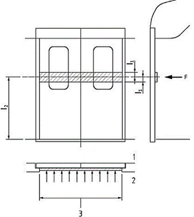
Fig. 1.
Point of application of the load generated by the passengers
The force must not cause
a non-elastic deformation or the door, which would make it uncontrollable. To
this end, a closed and locked door, together with the glass, must withstand the
force applied from the interior of the vehicle to the door leaf. This load will
be represented by the application of a load on a strip of 200 mm height,
located l2 = 1300 mm above
the threshold. The value of this load is 1000 N per each meter of the load
mentioned above (Figure 1: 1 - outer side of the door, 2 - inner side of the
door, 3 - uncovered inner area, l1
= 100 mm, 12 = 1300 mm, F = 1000 Nm-1). The locking
system on the sliding door must withstand a force of 1200 N in the opening
direction of opening. Forces in the vehicle equipment handles can be calculated
when the mass of the equipment is multiplied by the accelerations occurring in
practice, listed in Table 1.
Tab. 1
Considered
accelerations
|
Acceleration in axis. |
Acceleration |
Acceleration multiple |
|
x |
g |
±3 |
|
y |
g |
±1 |
|
z |
g |
1±c |
In Table 1, c = 2 g at
the end of the vehicle and it decreases linearly up to 0.5 g in the centre of
the vehicle, g = 9.81 m.s-2.
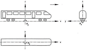
Fig. 2.
Vehicle coordinate system
The coordinate system
used for calculation is defined in Fig. 2. The positive direction of the x-axis
is parallel to the longitudinal axis of the vehicle and is in the travel
direction. The y-axis corresponds to the transverse axis of the vehicle and is
in the horizontal plane. The positive direction of the z-axis goes upward.
Consequently, numerous
requirements must be met, namely those related to fire protection, acoustic and
thermal insulation [3,5], electronic devices, reliability, availability,
maintainability, safety, protection against current and various environmental
conditions and loads caused by vibrations, which rise when riding on a track at
various speeds [12,33]. Great emphasis is put on noise protection, as this
well-known negative phenomenon is a consequence of every braking process [6,7,24,28].
2. DESIGN OF TECHNICAL SOLUTION FOR
THE METRO DOOR
In this section, the
technical solution of the metro door system is presented. Its virtual models
were made in the CAD software, which is used in the process of the rail
vehicles design [26,27].
The designed door system
is of a sliding plug door type (Fig. 3). The sliding plug doors work by
combining two movements. The first movement pushes the door from the sidewall.
The second movement moves the door alongside the sidewall. The door is ejected
in the range from 58 to 65 mm, measured from the sidewall.
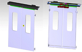
Fig. 3.
Designed door system
The main advantage of
these doors is that in the closed position, they are located in the plane of
the sidewall, therefore, they are suitable for mechanical washing, are more
aesthetic and have proper tightness. The disadvantage, in turn, is that the
duct or a drive is more complicated than in case of the sliding exterior and
pocket doors. The maximum dimensions of the system are the following: width
1856 mm and height 2190 mm. The height of the door leaf is 2077 mm and the
width is 781 mm. The weight of the door leaf is 50 kg and of the top of the
mechanism is 80 kg. The total weight of the entire system is 180 kg. The system
is driven by an electric motor. The power needed to open/close the door is
transmitted by means of a screw and guide nuts. The door system is attached to
a coarse structure with sixteen M10 screws. The top mechanism contains eight
screws - four of them are horizontally screwed into the C grooves on a coarse
construction, whereas the other four – vertically. Fig. 4 shows the
position of these screws.
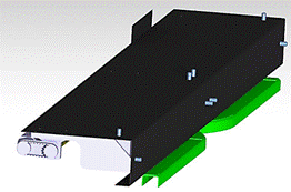
Fig. 4.
The position of screws in the door mechanism
The remaining eight
screws are located along the sides of the door leaves - four to the right and
four to the left. Two of them are used to attach the holding arm, and the
remaining two screws are used to attach the arm of the door conduct.
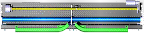
Fig. 5.
View of the mechanism from the bottom (without a set of arms)
In the sliding plug door
type system, the ejecting movement from the sidewall must be secured. The
motion is forced by the shape of guide rails mounted in the top mechanism (Fig. 5).
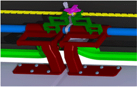
Fig. 6.
View of the system of arms
A wheel is mounted on
the arm that is screwed to the door leaf in each rail. When moving the guide
nut through the bolt when the door is opening, the wheel in the guide rail is
forced to extend the door leaf from the plane of the sidewall by curving the
guide rail. The force from the guide nut to the door leaf is transmitted by
means of a system of arms (Fig. 6). The door leaves are carried by the
supporting rod. The door wings are supported by a supporting rod and are
slidably and rotatably engaged.
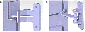
Fig. 7.
The holding arm (a), the bottom duct (b)
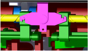
Fig. 8.
The lock
The holding arm (Fig.
7a) is not firmly attached to the door; it is attached to the coarse structure
and serves to prevent the vertical movement of the door in the direction of the
positive axis z. The holding arms are located on the side of both side wings.
The bottom duct with a specific rollers layout serves to conduct and support
the door when it is being opened or closed.
The bottom duct (Fig.
7b) with a specific rollers layout serves to conduct and support the door when
it is being opened or closed and prevents it from moving in the direction of
the x and y.
In order to prevent the
door from opening automatically, the mechanism is provided with a lock that
secures the system in the area of the guide nuts (Fig. 8). The lock is unlocked
by applying force to its lower part, for example, using a bowden cable that causes clockwise rotation.
3.
PARAMETRIC MODEL
It is assumed that the
vehicle is not moving and the doors are closed and locked. We will define the
external forces that will be taken into consideration, as well as the reaction
forces that represent the action of the door system on the coarse construction.
The external forces can act in different combinations. These combinations will
be defined in cases of load. The calculation itself, made in Microsoft Excel,
will be implemented in the parametric model. This model can be used for a quick
calculation of the forces acting on the coarse construction for various load
cases, with the possibility of entering the input parameters as required. Fig.
9 presents a simplified calculation model. The positions 1-7, as well as points
A, B, C, D, E, F, T1, T2, and T3 (Table 2), are visible.
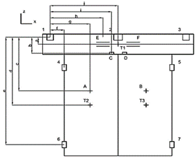
Fig. 9.
Model for calculation
Numbers 1-7 represent
the areas where the door system is attached to a coarse construction. Strength
analyses were calculated for each of these positions.
The individual distances
were measured in the CATIA model presented herein (Table 3).
Tab. 2
Description
of the individual points
|
A |
The effect of force on the door leaf from a passenger |
|
B |
The effect of force on the door leaf from a passenger |
|
C |
The point of contact of the guide rail with the guide wheel |
|
D |
The point of contact of the guide rail with the guide wheel |
|
E |
Sleeve on the carrier rod |
|
F |
Sleeve on the carrier rod |
|
T1 |
The centre of gravity of the top mechanism |
|
T2 |
The centre of gravity of the door leaf |
|
T3 |
The centre of gravity of the door leaf |
Tab. 3
The
distances determined in the Catia model
|
Distance |
Value (m) |
Distance |
Value (m) |
|
a |
0.025 |
h |
0.7435 |
|
b |
0.098 |
i |
0.8226 |
|
c |
0.861 |
j |
0.878 |
|
d |
1.127 |
k |
0.1205 |
|
e |
2.071 |
l |
0.173 |
|
f |
0.147 |
m |
0.117 |
|
g |
0.4875 |
n |
0.06 |
Positions 1 and 3 in
Fig. 9 are identical. It is the place of fixing the door system to a rough
construction with two screws. One screw is placed vertically, another one
horizontally. Position 2 consists of two vertically and two horizontally
positioned screws (Figure 10). In the calculation, it was assumed that all the
three positions – 1, 2 and 3, take the degrees of freedom in all three
axes.
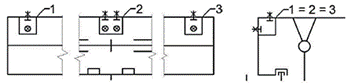
Fig. 10. Details
of positions 1, 2 and 3
Positions 4 and 5 (Fig.
9) represent the holding arm. They were not taken into consideration in the
equations in every case as they only prevent the door from moving in the
positive direction of the z-axis. It is mounted with two screws to the rough
construction. Positions 6 and 7 represent the bottom door guides. On the course
structure, the force effect is transmitted from the door through the swinging
arm. In the closed position of the door, they prevent it from moving in the
direction of the x and y axes. It is attached to the course structure with two
screws (Figure 11).
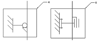
Fig. 11.
Details of positions 6 and 7
To obtain a correct and
simple solution, it should be determined which load case will be optimal for
the overall system. After having analysed the model, it was determined that the
optimal load case will be when a course structure will be loaded at all seven
points of contact. Therefore, such load variation (the most unfavourable one)
has been selected, as shown in Tab. 4.
Tab. 4
Considered
accelerations
|
Acceleration in
axis |
Acceleration |
Acceleration
multiple |
|
ax |
g = 9.81 m.s-2 |
-3 |
|
ay |
g = 9.81 m.s-2 |
-1 |
|
az |
g = 9.81 m.s-2 |
+3 |
For an accurate
calculation result, it is also necessary to consider the loads from the
passengers, namely 1000 N for each meter of the exposed door width in both
directions, as well as the force of the door seal, that is, 50 N per each meter
of the door leaf seal length and reduced to the centre of the door leaf. Last
but not least, it is necessary to consider the forces generated as a result of
the difference in the outside pressure relative to the inside of the vehicle,
that is, 1900 Pa, and it is needed to apply the effect to the centre of gravity
of the door leaves.
The external forces are
determined by the standard STN EN 12663 and by some customer requirements. The
forces are as follows:
- Faxi
– forces emerging from acceleration ax
(± 3g) in the x-axis direction
acting in the centres of gravity (1):
![]() , (1)
, (1)
where i = 1, that is, top mechanism, 2 –
door leaf,
![]() ,
,
- Fayi
– forces emerging from acceleration ay
(± 1g) in the y-axis direction
acting in the centres of gravity (2):
![]() , (2)
, (2)
- Fazi
– forces emerging from acceleration az
(-1·g a + 3·g) in the z-axis direction acting in the centres of gravity (3):
![]() , (3)
, (3)
- FTL
– forces emerging from the pressure differences between the inside and
outside of the vehicle p =
±1900 Pa, acting on the door leaves’ centres of gravity (4):
![]() , (4)
, (4)
where S = 1.622137 m2 is the inner
area of the door,
![]() ,
,
- FCES
– forces emerging from passengers ±1000 N per 1 meter of the
exposed door width, acting on the points A
and B (Figs. 1 and 9) on the door
leaves’ centres of gravity (5):
![]() , (5)
, (5)
where l0 = 0.59 m is exposed door
width,
![]() ,
,
- FTES
– gasket forces of 50 N per every meter of door leaf seal length acting
on the door leaves’ centres of gravity (6):
![]() , (6)
, (6)
where od = 3.639 m is the door leaf
seal length.
![]() .
.
The principle of
superposition was used to compile the equations of forces acting on the
vehicle’s structure. Firstly, the reactions from each external force are
determined separately. These are then summarised, according to the general
rules. Determination of the reaction effects due to the acceleration ax = -3·g can be seen
below (Fig. 12).
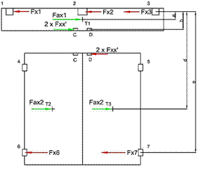
Fig. 12. A
free-body diagram of the door when ax = -3 g
Due to a large number of
the reaction effects, the calculation seems to be complicated. However, by
introducing certain simplifications and using this symmetry, this can be
avoided with a little impact on the calculation accuracy. It can be assumed
that (7):
![]() , (7)
, (7)
and (8):
![]() . (8)
. (8)
For the upper part of
the doors, it is as follows (9):
![]() . (9)
. (9)
And for the lower part
(10) (11):
![]() . (10)
. (10)
![]() (11)
(11)
The forces transferred
to the y-direction through the inclined plane on the guide rail (Fig. 13)
should also be calculated.
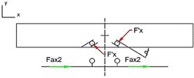
Fig. 13.
Reaction forces on the inclined plane of the guide rails when ax =
-3 g
Since the y-components
of F´x (F´xy) reactions are oriented opposite
to each other, it can be concluded that reactions on one side of the system
will have exactly the opposite direction as the reactions on the other side (Fy3
= -Fy1, Fy7 = -Fy6).
Fig. 14. Force reactions
transferred to the y-direction emerging from ax = -3 g
In this case, there is a
need to calculate a half of the model only, as the second half is identical as
far as geometry and load are concerned. It can be assumed that (12), (13),
(14), (15) and (16):
![]() , (12)
, (12)
![]() , (13)
, (13)
![]() , (14)
, (14)
![]() , (15)
, (15)
![]() . (16)
. (16)
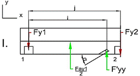
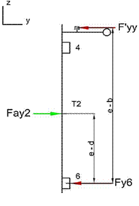
Fig. 15.
Free-body diagram for ay = -1 g
For the first body (Fig.
14 - the upper body) it is as follows in (17) and (18):
![]() , (17)
, (17)
![]() . (18)
. (18)
For the second body
(Fig. 14 – the lower body) it is as in (19):
![]() . (19)
. (19)
Based on Fig. 15, it can
be concluded again that only half of the model is necessary for the
calculation, due to the symmetry of both parts. Therefore, the next equations
apply (20) and (21):
![]() , (20)
, (20)
![]() . (21)
. (21)
For the upper body from
Fig. 15 equations, (22) and (23) apply:
![]() , (22)
, (22)
![]() . (23)
. (23)
For the lower body from
Fig. 15, (24) and (25) can be applied:
![]() , (24)
, (24)
![]() . (25)
. (25)
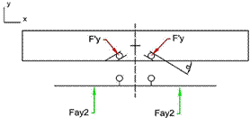
Fig. 16.
Reaction forces on the inclined plane of the guide rails when ay =
-1 g
In Fig. 16, it can be
seen that the forces transmitted to the x-axis through the inclined plane of
the guide rail cancel each other. For the force effects emerging from az = +3
g, according to Fig. 17, (26) and (27) will apply:
![]() , (26)
, (26)
![]() . (27)
. (27)
The equilibrium
conditions for the upper body in Fig. 17 are (28) and (29):
![]() , (28)
, (28)
![]() . (29)
. (29)
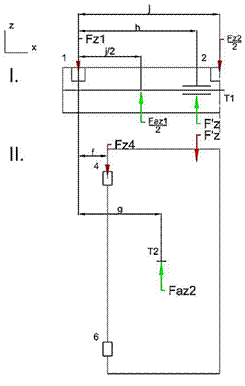
Fig. 17.
Reaction forces in the door system when az = 3 g
The equilibrium
conditions for the lower body in Fig. 17 are (30) and (31):
![]() , (30)
, (30)
![]() . (31)
. (31)
Our future activities in
this field will include the stress analyses of the designed structure, using
the finite element method. Also, since there is a structure [29,31,34] that
will be also submitted to the dynamic loads, investigation of the modal
properties [13] and creation of a multi-body system for identification of the
dynamic properties will be performed [15,20,23].
4. CONCLUSION
This article dealt with the design of a technical solution for the metro
vehicle doorway. The designed door was of the forward-sliding type. The
advantages of this type of door include aesthetics, tightness, sound and
thermal insulation, maintenance costs and small installation space. Also
discussed was the creation of a parametric model for calculating the external
and reaction forces representing the action of a door system on a
vehicle’s structure. Presented therein was the creation of the first
three loading force effects, namely, the inertial effects of the door's own mass
in all three directions (x, y, z). The individual door system dimensions were
defined and identified using the Catia model. The prepared part of the
parametric model was used in conjunction with other force effects from
passengers, gaskets and overpressure to calculate the individual effects on the
door system suspension.
A parametric model was created in Microsoft Excel and all the equations
(1-31) that were compiled will be converted into a matrix form. The software
will calculate the unknown variables by searching for the inverse matrix of
inputs. This model should be used to approximate and quickly quantify the force
effects of the door on the vehicle’s structure when changing different
parameters. After obtaining all the necessary equations, these will be
organised and arranged as clearly as possible for future use. Finally, the
compiled model of the equation enumerates and suggests the components that
enable the safe use of the door system in operation. This will be verified for
strength analysis by the FEM software.
Source of funding
The work was supported by the Cultural and Educational Grant Agency
of the Ministry of Education of the Slovak Republic. The project no.: KEGA
077ŽU-4/2017: Modernization of the Vehicles and engines study program.
This work was created with the financial support of the Agency for
Support of Research and Development of the Ministry of Education, Science,
Research and Sport of the Slovak Republic; VEGA 1/5058/18: Research of the
interaction of a braked railway wheel set and track in the simulated
operational conditions of a vehicle running on a track on the test bench.
References
1.
Aristizabal Mauricio, Jaime L.
Barbosa, German R. Betancur, Leonel F. Castañeda, Bogdan
Żółtowski. 2014. “Structural diagnosis of rail vehicles
and method for redesign”. Diagnostyka 15(3): 23-31.
2.
Bureika
Gintautas, Eduardas Gaidamauskas, Jonas Kupinas, Marijonas Bogdevicius, Stasys
Steisunas. 2017.
„Modelling the assessment of traffic risk at level crossing of Lithuanian
railways”. Transport 32(3):
282-290. ISSN 1648-4142. DOI: 10.3846/16484142.2016.1244114.
3.
Droppa Peter, Ivan Kopecký. 2014. „Possibility of using the
thermos vision diagnostics for special mobile technics”. In 18th International Conference
on Transport Means, „Transport Means 2014”: 393-396. Kaunas
University of Technology and Klaipeda University, Lithuania. 23-24 October
2014, Kaunas, Lithuania. ISSN 1822-296 X.
4.
Galliková Jana, Vladimír Stuchlý, Roman
Poprocký, Peter Volna. 2018. „Model calculations of posterior reliability indicators
for the proposal of the maintenance system”. MATEC Web of Conferences 157. eISSN 2261-236X. DOI:
10.1051/matecconf/201815708003.
5.
Gerlici Juraj, Mykola Gorbunov, Kateryna Kravchenko, Prosvirova O, Tomas
Lack. „Noise and temperature reduction in the contact of tribological
elements during braking”. MATEC Web
of Conferences 157. eISSN 2261-236X. DOI: 10.1051/matecconf/201815702010.
6.
Gerlici Juraj, Mykola Gorbunov, Kateryna Kravchenko, Olga Prosvirova,
Tomas Lack. 2017. „The innovative design of rolling stock brake
elements”. Komunikacie (Communications -
Scientific Letters of the University of Zilina) 19 (2): 23-28. ISSN 1335-4205.
7.
Gerlici Juraj, Mykola Gorbunov, Kateryna Kravchenko, Olga Prosvirova,
Tomas Lack, Vladimir Hauser. 2018. „Assessment of innovative methods of
the rolling stock brake system efficiency increasing”. Manufacturing Technology 18 (1): 35-38.
ISSN 1213-2489. DOI: 10.21062/ujep/49.2018/a/1213-2489/MT/18/1/35.
8.
Gerlici Juraj, Tomas Lack, Zuzana Ondrova. 2007. „Evaluation of
comfort for passengers of railway vehicles”. Komunikacie (Communications - Scientific Letters of the University of
Zilina) 9(4):
44-49. ISSN 1335-4205.
9.
Grenčík Juraj, Roman Poprocký, Jana Galliková,
Peter Volna. 2018. „Use of the risk assessment methods in maintenance for
more reliable rolling stock operation”. MATEC Web of Conferences 157. eISSN 2261-236X. DOI:
10.1051/matecconf/201815704002.
10. Guo Xinxin, Xuhai Pan,
Zhilai Wang, Juan Yang, Min Hua, Juncheng Jiang. 2018. “Numerical
simulation of fire smoke in extra-long river-crossing subway tunnels”. Tunnelling and underground space technology
82: 82-98. ISSN 0886-7798. DOI: 10.1016/j.tust.2018.08.002.
11. Hauser Vladimir, Olena
Nozhenko, Kateryna Kravchenko, Mária Loulová, Juraj Gerlici,
Tomáš Lack. 2017. “Impact of the wheel set steering and the
wheel profile geometry to the vehicle behaviour when passing a curved
track”. Manufacturing Technology
17 (3): 306-312. ISSN 1213-2489.
12. Jakubovicova Lenka,
Milan Saga, Marian Handrik. „Numerical analysis of stiffener for hybrid
drive unit”. MATEC Web of
Conferences 157. eISSN 2261-236X. DOI: 10.1051/matecconf/201815702015.
13. Klimenda Frantisek,
Josef Soukup. 2017. „Modal analysis of a thin aluminium plate”. Procedia Engineering 177: 11-16. ISSN
1877-7058. DOI: 10.1016/j.proeng.2017.02.176.
14.
Kosicka E., Kozłowski E.,
Mazurkiewicz D. 2015. „The use of stationary
tests for analysis of monitored residual processes”. Eksploatacja i Niezawodnosc – Maintenance and Reliability
17(4): 604–609. DOI: http://dx.doi.org/10.17531/ein.2015.4.17.
15. Kostrzewski Mariusz,
Melnik, Rafał. 2017. „Numerical dynamics study of a rail vehicle
with differential gears”. Procedia
Engineering 192: 439-444. ISSN 1877-7058. DOI:
10.1016/j.proeng.2017.06.076.
16. Lack Tomas, Gerlici
Juraj. 2008. „Analysis of vehicles dynamic properties from: the point of
view of passenger comfort”. Komunikacie
(Communications - Scientific Letters of the University of Zilina) 10(3): 10-18. ISSN
1335-4205.
17. Leitner Bohus, David
Rehak, Robertas Kersys. 2018. „The new procedure for identification of
infrastructure elements significance in sub-urban railway transport”. Communications – Scientific Letters of
the University of Zilina 20 (2): 41-48. ISSN 1335-4205.
18. Loulová
Mária, Andrej Suchánek, Jozef Harušinec. 2017.
„Evaluation of the parameters affecting passenger riding comfort of a
rail vehicle”. Manufacturing
Technology 17 (2): 224-231. ISSN 1213-2489.
19. Luskova Maria, Bohus
Leitner. 2018. „Extreme weather impact on transportation and energy
infrastructure”. In 22nd
International Scientific on Conference „Transport Means 2018”:
569-573. Kaunas University of Technology, Kaunas, Lithuania. 03-05 October
2018, Trakai, Lithuania. ISSN 1822-296 X.
20.
Madleňáková Lucia,
Matúšková Mária, Madleňák Radovan,
Rudawska Anna, Rybicka Iwona. 2018. “Solutions of the Roller Conveyor in
Terms of Logistics Provider”. Advances
in Science and Technology Research Journal Volume 12(4): 1-9. December 2018. DOI:
https://doi.org/10.12913/22998624/92098.
21. Melnik Rafał,
Mariusz Kostrzewski. 2012. „Rail vehicle’s suspension monitoring
system – analysis of results obtained in tests of the prototype”. Key Engineering Materials 518: 281-288.
ISSN 1013-9826. DOI: 10.4028/www.scientific.net/KEM.518.281.
22.
Michalski R., S. Wierzbicki.
2008. „An analysis of degradation of vehicles in operation”. Eksploatacja i Niezawodnosc –
Maintenance and Reliability 1: 30-32.
23. Sapietova Alzbeta, Juraj
Bukovan, Milan Sapieta, Lenka Jakubovicova. 2017. „Analysis and
implementation of the input load effects on an air compressor piston in
MSC.ADAMS”. Procedia Engineering
177: 554-561. ISSN. 1877-7058. DOI: 10.1016/j.proeng.2017.02.260.
24.
Skliros Christos, Esperon Miguez Manuel,
Fakhre Ali, Jennions Ian. 2019. „A review of model based and data driven
methods targeting hardware systems diagnostics”. Diagnostyka 20(1): 3-21.
DOI: https://doi.org/10.29354/diag/99603.
25. Skrucany Tomas, Martin
Kendra, Milan Skorupa, Juraj Grencik, Tomasz Figlus. 2017 „Comparison of
selected environmental aspects in the individual road transport and the railway
passenger transport”. Procedia
Engineering 192: 806-811. ISSN 1877-7058. DOI:
10.1016/j.proeng.2017.06.139.
26. Šťastniak
Pavol. 2015. „Wagon chassis frame design with adaptable loading
platform”. Manufacturing Technology
15 (5): 935-940. ISSN 1213-2489.
27. Šťastniak
Pavol, Marian Moravčík, Peter Baran, Lukáš Smetanka.
2018. „Computer aided structural analysis of newly developed railway
bogie frame”. MATEC Web of
Conferences 157. eISSN 2261-236X. DOI: 10.1051/matecconf/201815702051.
28. Suchánek Andrej,
Jozef Harušinec, Mária Loulová, Peter Strážovec.
2018. „Analysis of the distribution of temperature fields in the braked railway
wheel”. MATEC Web of Conferences
157. eISSN 2261-236X. DOI: 10.1051/matecconf/201815702048.
29. Svoboda Martin, Josef
Soukup, Alena Petrenko. 2014. „Use of FEM programs in solving general
unbalance simple mechanical system of rigid, flexible stored bodies”. In 52nd International Conference
on Experimental Stress Analysis „EAN 2014”. Jan Evangelista
Purkyně University, Ústí nad Labem, Czech Republic. 2-5 June
2014, Marianske Lazne, Czech Republic. ISBN 978-8023-1037-7.
30. Vatulia Glib, Anatoliy
Falendysh, Yevhen Orel, Mykhailo Pavliuchenkov. 2017. „Structural
improvements in a tank wagon with modern software packages”. Procedia Engineering 187: 301-307. ISSN
1877-7058. DOI: 10.1016/j.proeng.2017.04.379.
31. Figlus Tomasz, Łukasz Kuczynski. 2018. „Selection of a
semi-trailer for the haulage of long oversize loads, taking into account an
analysis of operational damage". XI International
Science-Technical Conference Automotive Safety. Publisher: IEEE, DOI: 10.1109/AUTOSAFE.2018.8373342.
32. Wang Wenhe, Tengfei He, Wie
Huang, Ruiqing Shen, Qingsheng Wang. 2018. „Optimization of switch modes
of fully enclosed platform screen doors during emergency platform fires in
underground metro station”. Tunnelling
and underground space technology 81: 277-288. ISSN 0886-7798. DOI:
10.1016/j.tust.2018.07.015.
33. Yao Shunguang, Xianliang
Xiao, Ping Xu, Qiuyun, Quanwei Che. 2018. „The impact performance of
honeycomb-filled structures under eccentric loading for subway vehicles”.
Thin-walled structures 123: 360-370.
ISSN 0263-8231. DOI: 10.1016/j.tws.2017.10.031.
34. Żółtowski
Bogdan, Żółtowski Mariusz. 2018. „Selection measure of
energy propagation in vibration diagnostic and modal analysis methods”. Diagnostyka 19(4): 19-26. DOI:
https://doi.org/10.29354/diag/94753.
35.
Žaldarys G., S.J.
Chodočinskas, A. Štuopys. 2008. “Investigation of rail metal of
Kaunas fortress fortification narrow – gauge railway”. Mechanika 5(73): 74-78. ISSN 1392-1207.
Received 04.09.2019; accepted in revised form 15.11.2019
![]()
Scientific
Journal of Silesian University of Technology. Series Transport is licensed
under a Creative Commons Attribution 4.0 International License