Article
citation information:
Vinogradov, B. Mechanical systems with
air spring flexible elements. Scientific
Journal of Silesian University of Technology. Series Transport. 2019, 103, 199-207. ISSN: 0209-3324. DOI: https://doi.org/10.20858/sjsutst.2019.103.16.
Borys VINOGRADOV[1]
MECHANICAL
SYSTEMS WITH AIR SPRING FLEXIBLE ELEMENTS
Summary. The purpose of this study was to assess the
effectiveness of flexible air-spring systems operating in parallel to share the
total load, taking into account installation and in-operation errors. This
study presented experimental and calculated characteristics of the air spring
flexibility and its dependence on the polytropic index and additional volume.
It considered patterns of load distribution between the air springs when they
are operating in parallel to share the total load for the case when the air
springs were used as the supporting elements for various machines and units,
and between transmission lines containing flexible couplings, where air springs
were installed as flexible elements.
Keywords: air spring, rubber-cord shell, load distribution, flexible
1. INTRODUCTION
A wide standard size series of rubber-cord air springs with a load
capacity from 350 N to 230,103 Nwas developed and is being produced. Prospects
for effective use of air springs as hydraulic inertial transducers of motion
[1], vibration dampers and shock absorbers for rail vehicles [2] are being
considered. The use of pneumatic couplings in machine drives solved the problem
of limiting dynamic loads [3, 7]. One of the most important features of
pneumatic couplings is the ability to control their stiffness and, accordingly,
torsional vibrations of mechanical systems [4]. Furthermore, air springs may be
effectively used as flexible elements sharing the total load, and in systems
with a branched power flow.
2.
FLEXIBILITY CHARACTERISTICS OF AIR SPRINGS
When choosing a reference
point in the static equilibrium position, the characteristics of the air spring flexibility has the form
![]() (1)
(1)
where ![]() ,
, ![]() are the gas volume and overpressure in the air spring bellows in the static equilibrium position;
are the gas volume and overpressure in the air spring bellows in the static equilibrium position; ![]() is atmospheric pressure;
is atmospheric pressure; ![]() is the air spring effective area depending on the
displacement x.
is the air spring effective area depending on the
displacement x.
The experimental studies of the flexibility
characteristics were carried out for the Connect MD 1895 double convolution air spring, according to the
manufacturer’s company catalogue, its features are:
weight - 2.95 kg; working pressure - 0.5 MPa; maximum pressure - 0.8 MPa;
minimum pressure - 0 MPa; working diameter - 265 mm; assembly height 210 mm;
load capacity - 900 kg. The internal volume of the air spring with its design height of 140 mm
is 3.64 litres. Based on experimental studies, the dependence of the air spring
effective area on its deformation is represented by a first-order polynomial.
![]() (2)
(2)
where ![]() is the
effective area in the static equilibrium position, m2, P is the external load, β = 0.118 m.
is the
effective area in the static equilibrium position, m2, P is the external load, β = 0.118 m.
The difference between
the experimental and calculated flexibility of the air spring, when compared by
the formula (1) given (2), does not exceed 2%, which allows for further
consideration of it as an actual flexibility [5].
Expanding the expression
(1) considering (2) in a Taylor series and retaining only the first two terms,
we obtain
![]() , (3)
, (3)
where
![]() ,
,
![]() (4)
(4)
Figure 1 shows the
linearised flexibility characteristics, determined by the formula (4), with the
actual flexibility determined by the formula (1)
The rubber-cord flexible element is a closed system, where heat will be evolved due to internal air friction during
each cycle of air compression
and expansion. The value of the polytropic index depends on the conditions of heat removal. The environmental conditions being the same, the number of compression and
expansion cycles over the same time period grows with an increase in the vibration frequency; with the lack of proper heat removal, the polytropic index can take values n > 1.4. In most cases, the calculations take n = 1.3. As n
increases, for example, from 1.3 to 1.6, as it follows from expression (4), the air spring stiffness and the natural frequency increase by
1.13 (Figure 2a) and 1.06
times, respectively, which in practice can be neglected in most cases.
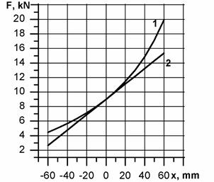
Fig. 1. Actual and
linearised flexibility characteristics of the air spring
|
|
|
|
а |
в |
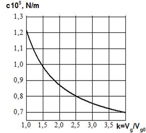
Fig. 2. The
dependence of the air spring stiffness on the polytropic index (a) and the
additional volume (b): k is the ratio
of the total volume of gas (including the added gas) to the initial volume
The rubber-cord flexible element is a closed system, where heat will be evolved due to internal air friction during
each cycle of air compression
and expansion. The value of the polytropic index depends on the conditions of heat removal. The environmental conditions being the same, the number of compression and
expansion cycles over the same time period grows with an increase in the vibration frequency; with the lack of proper heat removal, the polytropic index can take values n > 1.4. In most
cases, the calculations take n = 1.3. As n increases, for example, from 1.3 to 1.6, as it follows from expression (4), the air spring stiffness and the natural frequency increase by
1.13 (Figure 2a) and 1.06
times, respectively, which in practice can be neglected in most cases.
One of the advantages of
systems that use air springs as flexible elements is the ability to control
their flexibility by adding an additional volume (Fig. 2b)
3. LOAD DISTRIBUTION
BETWEEN AIR SPRINGS OPERATED IN PARALLEL TO SHARE THE TOTAL LOAD
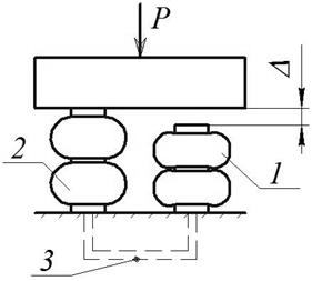
Consider the case where air springs are used as support for various
machines and units. These mechanical systems include
vibratory machines or other aggregates that apply air springs as flexible elements. This is the case, where installation errors may occur when the support of one air spring is displaced by Δ relative to the other (Fig. 3).
When pressure is
supplied to the bellows of each air spring, the error is compensated and the
air springs will attain equal pressures. Interconnected air springs adjust the pressure automatically. In the state of static equilibrium position, the first air spring will undergo a deformation smaller by the value of
Δ. As a result, the effective areas of the air springs in the static equilibrium position
will be different;
pressures pm0 being the same, the load between the air springs will not be uniformly distributed.
Fig. 3.
Flexible system with air springs mounted in parallel: 1, 2 - air springs; 3 -
common pipeline; P - external load; Δ - the error
For the case of independent
operation of air
springs, the
equilibrium equations will take the form:
![]() ,
, ![]() ,
, ![]() ,
,
where ![]() ,
, ![]()
Substituting S (x1),
S (x2), p1 , p2 from (1), we obtain the system of equations
![]() , (5)
, (5)
![]() , (6)
, (6)
The value of x in the static equilibrium position is determined from the
following condition:
+![]() .
.
When linearising the flexibility characteristics, the stiffness of the air springs is determined by the following expressions
![]() ,
,
(7)
![]()
The calculated values of the
linearised air
spring stiffnesses versus the magnitude of the error Δ are
shown in Figure 4.
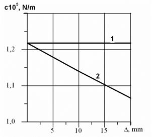
Fig. 4.
Dependence of the air spring stiffness on the error Δ for independent air springs, the
initial pressures pm0 being
equal
The calculated data showed that the mounting errors, in this case, have little effect on the change in
stiffness. Even with an error of 20 mm, the stiffnesses of the air springs differ by no more than 1.2 times.
In the static equilibrium position, the air springs will take the force
![]() ,
, ![]() (8)
(8)
The non-uniform distribution of the load will be characterised by the coefficient kN, which shows how many times the force
taken by the most loaded air spring exceeds the force taken under a uniform distribution of the
total load
![]() (9)
(9)
Considering that с2 > с1, Fmax = F2,
we obtain
![]() . (10)
. (10)
When ![]()
![]()
The dependence of the non-uniform load distribution factor kN on the magnitude of the error
Δ is shown in Figure 5.
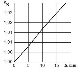
Fig. 5. The dependence
of the non-uniformity factor kN
on the error Δ, the initial pressures pio being equal
As can be seen from the
expression (11) and (14), in this
case, the non-uniform load was only caused by a change in the effective
area, which, in turn, is caused by the mounting error.
Analyzing the data obtained,
we can conclude that the use of air springs as flexible elements operating in parallel ensures a practically
uniform distribution of the load between them. Even with an error Δ = 20 mm, the non-uniform distribution of load is about 3%.
4. LOAD DISTRIBUTION BETWEEN
TRANSMISSION LINES INCORPORATING PNEUMATIC FLEXIBLE COUPLINGS
As an example, we considered a twin-motor synchronous drive, whose transmission lines incorporate couplings with air springs installed as flexible elements (Fig. 6). Figure 1 shows a flexible coupling (pneumatic coupling) developed by the Polish
company, FENA, at the Technical University in
Košice (Slovakia) [5].
The feature of the synchronous drive is that the
rotational speed of the motors does not depend on the load. At the moment, when the motors come into synchronism, their rotors may undergo angular
displacement in respect to each other; this leads to an error, which we will further call an “angular mismatch”. By the angular mismatchDj, we understood the angle by which it is necessary to align the rotors
of the engine in order to provide a uniform load distribution. Misalignment of
the rotors may also be caused by the take-up of clearances in the kinematic
chain.
The force taken by each air spring is determined by the following expressions:
![]() , (11)
, (11)
![]() , (12)
, (12)
![]() +
+
+![]() . (13)
. (13)
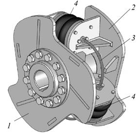
Fig. 6.
Flexible pneumatic coupling:
1 - drive
part; 2 - driven part; 3 - pipeline; 4 - pneumatic flexible elements
(rubber-cord air springs)
The variation of the non-uniformity factor versus the error for this case is shown in Figure 7.
In the case, when the bellows of the air springs of each coupling are interconnected, the mismatch of the motor rotors will be compensated by
stretching the air spring bellows in the coupling of the first motor transmission line and compressing the air spring bellows in the coupling of the other motor transmission line, the pressure within the air springs being the same [6].
As a result, the non-uniform load distribution between the motors will only be due to the different effective
areas of the air
springs in the couplings; it can be determined by the formula (10). With a relatively high error Δ =
20mm, the non-uniform
load distribution
will be about 3% (Figure 7). An absolutely uniform load distribution
can be achieved by using an automatic system that enables control of the pressure within the bellows of the air springs [6].
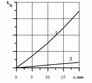
Fig. 7. The load distribution
factor versus the magnitude of the angular mismatch of the synchronous motor
rotors ∆ = r∆φ0, (r is the
coupling radius): 1, 2 - couplings with independent and interconnected air
springs, respectively
5. CONCLUSIONS
1.
In the operation of pneumatic systems, the
polytropic index n will change
depending on the conditions of the heat removal. With an increase in n, for example, from 1.3 to 1.6, the air
spring stiffness will increase by 1.13 and the natural frequency by 1.06 times,
which in most cases can be neglected in practice.
2.
In cases, when the air springs are mounted
in parallel to support the total load, the load will be almost uniformly
distributed between the air springs, even with equal initial air pressures in
their bellows, and in spite of the relatively bad mounting errors (20 mm).
3.
The use of flexible couplings in
mechanical systems with branched power flows, for example, in twin-motor
synchronous drives where air springs are used as flexible elements, allows an
even distribution of the load between the transmission lines.
References
1.
Buryan
Yu.A., V.N. Sorokin, M.V. Silkov, Yu.F. Galuza. 2015. “Hydraulic inertial
motion transformer with rubber-cord casing”. Omsk Scientific Bulletin
1(137): 30-33.
2.
Manashkin
L., S. Myamlin, V. Prikhodkoю 2009. Oscillation
dampers and shock absorbers in railway vehicles (mathematical models).
Dnipropetrovsk. 180 p. DOI: 10.15802/978-966-348-121-0.
3.
Czech P. 2012. „Determination of the course of pressure in an
internal combustion engine cylinder with the use of vibration effects and
radial basis function - preliminary research”. Communications in Computer and Information Science 329: 175-182. 12th International
Conference on Transport Systems Telematics (TST 2012). Katowice-Ustron, Poland,
October 10-13, 2012. Telematics In The Transport Environment. DOI: https://doi.org/10.1007/978-3-642-34050-5_21.
4.
Sága M., L.
Jakubovičová. 2014. “Computational analysis of contact stress
distribution in the case of mutual stewing of roller bearing rings”. Novel Trends in Production Devices and
Systems, Applied Mechanics and Materials 474: 363-368.
5.
Sapietova
A., V. Dekys. 2016. „Use od Msc. Adams software product in modeling
vibration sources”. Komunikacie
1a(101): 101-107.
6.
Urbanský
M., J. Homišin, P. Kaššay, J. Krajňák. 2018. „Measurement of air springs volume using indirect method in the design of
selected pneumatic devices”. Acta
Mechanica et Automatica 12(1): 19-22. ISSN 1898-4088.
7.
Żółtowski
B., M. Żółtowski. 2018. “Selection measure of energy
propagation in vibration diagnostic and modal analysis methods”. Diagnostyka 19(4):19-26. DOI: 10.29354/diag/94753.
Received 19.01.2019; accepted in revised form 05.05.2019
![]()
Scientific
Journal of Silesian University of Technology. Series Transport is licensed
under a Creative Commons Attribution 4.0 International License