Article
citation information:
Martinec, F., Koblen, I.,
Krajčík, V., Lazar, V. Possible solutions for the flight of several unmanned
aircraft systems in urban areas. Scientific
Journal of Silesian University of Technology. Series Transport. 2019, 103, 105-116. ISSN: 0209-3324. DOI: https://doi.org/10.20858/sjsutst.2019.103.9.
František MARTINEC[1],
Ivan KOBLEN[2], Vladimír
KRAJČÍK[3], Václav LAZAR[4]
POSSIBLE
SOLUTIONS FOR THE FLIGHT OF SEVERAL UNMANNED AIRCRAFT SYSTEMS IN URBAN AREAS
Summary. The development and use of unmanned airborne systems
are currently undergoing a huge transformation. This allows the development of
computer technology, new materials for their construction. Reducing airborne
funds would enable them to be widely used. This applies to not only military
use but also mainly civil use, industrial and commercial use as well. This new
use brings new challenges, including security, legislative, technical, social,
and so forth. This paper focused on the possibility of having several Unmanned
Aircraft Systems movement in urban areas. It contains the description of a
philosophical proposal of flight corridors and flight trajectories in urban
areas with the example of a small town.
Keywords: Unmanned Aircraft
System, urban area, pilot-operator, flight corridor, flight trajectory
1. INTRODUCTION
The use of several
Unmanned Aircraft Systems (UAS) in urban areas has proven to be one possible
solution for parcel delivery to customers in the future, however, it is
forbidden according to the current European and worldwide legislation. Quick
delivery of goods to the customer is the current trend in business and this is
what new devices like Unmanned Aircraft Systems seek. Presently used as one way
of delivery for individual goods, it is being explored for mass delivery of
goods in the future.
It is concerned mainly
with light package weighing up to 20 kg, delivered to customers through
Unmanned Aircraft Systems with maximal take-off weight up to 27 kg.
The aim
of this paper is to analyse possible conditions and propose possibilities under
which several Unmanned Aircraft Systems would fly in urban areas in the future.
2. PRINCIPAL CONDITIONS FOR FLIGHT OF SEVERAL UAS
The philosophy of
movement of several UAS (n UAS) requests to introduce into the system of such
conditions, which assure:
a) Flight safety –
not only safe mission fulfilment;
b) The solving of a
psychological problem – the introduction of such operations into the
lives of people without any apprehension resulting from potential risk.
Until
now, no survey of peoples’ reaction on the flight of one or several UAS
in the town was conducted. The simple survey focused on the use of auto
aircraft in the Czech Republic turned out in the negative (40% of people voted
in favour of, while 60% of people counter voted against);
c)
UAS technical solution;
d) Flights in solid
legislative conditions.
The above-mentioned
conditions are linked together. Safety is interconnected with technical and
legislative problems. We will deal more with the technical and partially with
safety and psychological problems. These conditions are as follows (Figure 1):
-
exact and reliable UAS control, also without direct visibility,
-
necessity of autonomous control,
-
necessity of coordination with other UAS,
-
solution of safety – collisions,
-
automatic landing at take-off place,
-
automatic emergency landing,
-
requirements on safety design and meeting of all requirements resulting
from legislation, etc.
![]() Ambient
effects Satelite
navigation, ATC instructions
Ambient
effects Satelite
navigation, ATC instructions
![]() Wind speed, VFR, IFR
Wind speed, VFR, IFR

Input requirements for FT
![]() target,
trajectory definition, trajectory Flight
trajectory (FT)
target,
trajectory definition, trajectory Flight
trajectory (FT)
![]() profile,
flight speed, safety criteria
profile,
flight speed, safety criteria
![]()
![]()
![]()
Coordination
with other UAS control
(manual, automatic)
Collisions
solving
Fig.
1. Model philosophy of more - n UAS movement
Above conditions must be meet by
all UAS with strict compliance.
3. INITIAL AMBIENT CONDITIONS FOR FLIGHT OF SEVERAL UAS
An ambient condition is
another important determining factor for flight movement of several UAS,
especially in urban areas.
The most important
ambient conditions are:
a)
day time,
b)
Weather,
c)
Environment,
d)
building obstacles,
e)
energy obstacles,
f)
emergency landing possibility.
a) Day time is an important parameter because during the day it
is easy to make a visual sighting of the controlled UAS, as such normal people
can react to its presence, accordingly. However, it is difficult to sight a UAS
at night owing to the ensued darkness.
b) Weather: 1) Under visibility –
in wind speed (WS) up to 20 km/h - IFR
2) During the night and
in reduced visibility in the course of automatic control assurance in meeting
landing safety in wind speed of up to 20km/h - VFR
Therefore, functional
dependency for flight trajectory (FT) can be formulated thus:
FT = f (IFR, VFR, WS) (1)
c) Environment: These are the towns and villages divided according to
habitation structure from the security point of view. Different requirements
are observed in different sections of these localities, that is, populated
area, park, square or field, meadows and forest. Presently, some enthusiasts
have been observed flying UAS around the residential houses without observing
safety standards. From a safety viewpoint, it might be impossible to avoid
collision with humans and UAS in the future.
d) Building and other obstacles: The building landscape is relatively
fast changing. Due to this fact, the flight paths actualisation must be
frequently reviewed on a periodic basis based on the speed of changes in the
relevant location.
e) Energy obstacles: In the proposed flight trajectories, we almost
collided with energy routes (for example, high voltage distribution that can
reach our flight trajectory). Due to this fact, energy routes significantly
appear at altitudes and visibility points of view, this was demonstrated
several times during flights of manned aircraft and helicopters in low
altitude.
f) Emergency landing possibility. This problem needs to be solved in
case of UAS failure, deficiency of power energy, etc. The places selection for
emergency landing must be done in advance and take into account the UAS
emergency systems for emergency landing.
4. PHILOSOPHY OF SEVERAL UAS MOVEMENT
Philosophy of several
UAS movement is possible, based on the Line staff system with the support of:
·
multi-satellite navigation for accurate and particularly reliable
definition of trajectory points with accuracy of maximum 2 m,
·
updated maps with aircraft view, with panorama and 3D execution (road
and water routes),
·
access to internet and phone (mobile phone network) connection,
·
equipping with a video system for evaluation of position and movement in
real time,
·
equipping with a transponder,
·
other important orientation devices.
Example:
A,B,C, D, … - fundamental
orientation control and safety points
Cn1 - Cnn……
- target points
a, b, c, d,… - movement trajectories – flight
paths
baseline
line
The larger village is
divided to individual main settled parts, where it may threaten the risk for
the population and, hence, propose the main flight trajectory with branch lines
– orientation and control points meeting the safety criteria and then,
side trajectories for meeting the purpose of the mission Figure 2.
Side
target trajectories
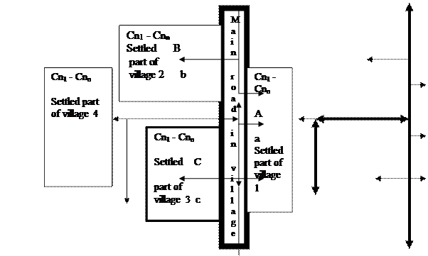
Cn1
- Cnn
Main trajectory
Fig.
2. Principal village divided into individual parts
For a smaller town, it
is possible to come out from its principal structure and propose closed settled
agglomerations and among these introduce and select suitable safe flight
trajectories as shown in Figure 3 and Figure 4, respectively.
5. PHILOSOPHY OF FLIGHT CORRIDORS AND FLIGHT TRAJECTORIES
It is necessary to
define the needed data for a flight in the flight space (flight corridor)
– “tunnel” with the exact defined and approved flight
trajectory (defined course, flight altitude and speed range), with the defined
control points and potential crossing of flight corridors and flight
trajectories. Division of corridors can be according to local organisation and
operation intensity in several flight trajectories. The flight corridor
illustrated in Figure 5; it is divided into four flight trajectories in Figure
5a and six flight trajectories in Figure 5b.
Flight in the flight
corridor “tunnel” must be well defined and must have defined space
for entrance and exit of UAS from the flight corridor. Regarding the current
division of flight corridors, it turns out to be a suitable corridor up to
altitude maximum 300 m. It is valid without the definition of safety
separation. The developed legislative documents accept maximum UAS flight
altitude of up to 150 m. Due to this fact, the flight corridor begins from the
minimum UAS flight altitude, that is, 10 m and maximum altitude up to 150 m.
High-altitude distance of flight corridor will be 50 m. Width distance would arise
from the safety condition defined in the given locality. Practical experience
demonstrates that this distance would be in the range 5-20 m.
![]()
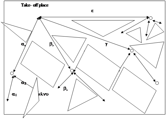
Fig. 3. Philosophy of
town divided into individual parts
![]()
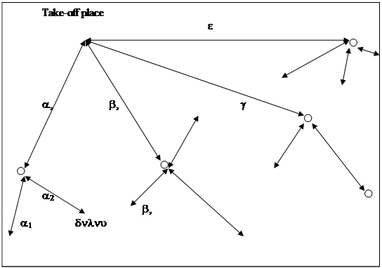
Fig. 4. Philosophy of selected and exactly defined town flight
trajectories in individual parts
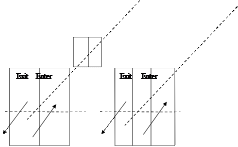
Exit Enter Exit Enter
a)
b)
Fig. 5. Philosophy of flight corridors and flight trajectories,
a) corridor with four flight trajectories, b) corridor with six flight trajectories
6. FLIGHT CORRIDORS ELABORATION PROCEDURE FOR UAS OPERATION
Flight corridors (FC) are designated only for UAS operation. In the framework of our considerations, we assume the UAS is used, for example, by the distribution companies, for the realisation of the delivery of parcels from the company warehouse to the target destination. The target destination is subsequently the place selected in advance by the customer (buyer). Selection of target destinations corresponds with the FC network outside the town. Customer selects parcel delivery place during order.
The idea of FC in the selection of spaces should be assured the following conditions:
1) Adequate safety.
2) Adequate place service.
3) Possible connection of published sectors.
These general conditions are subsequently applied to the concrete decision-making process for FC selection. FC is first selected in a horizontal plane with the help of an internet map. Herein, the selection is controlled by undermentioned requirements for the fulfilment of initial conditions.
Subsequently, the vertical plane was proposed. It contents describe the accrued FC only. Operation of FC depends on equipping of unmanned aircraft only. It assumes mostly autonomous flights (over advance planned routes outsider FC) without visual control of pilots-operators, which is in discrepancy with the actual formulation of regulations almost all around the world. FC eventually consists of three more aviation routes (depending on the width of the road, water surface and railway) within them in a UAS operation. FC placed above the earlier selected spaces in that manner pose no safety risk.
6.1. Horizontal selection of flight corridors
Suitable spaces (trajectories) for flight corridors (FC) creation were selected through the use of internet maps. These spaces are:
1) Existing transport lines - roads, railways, cycle paths.
2) Watercourses- lakes.
3) Energy routes – electric, oil, gas
4) Free surfaces – meadows, forests, mountain ranges.
Due to the selection of these spaces, the safety of the flight trajectories is increased. Possible incidents on roads, watercourses or railways would not have fatal results. In addition, they ensure the possibility of satisfactory UAS separation from persons, because increased movement of persons in these areas is not expected. These usable trajectories were marked on the map. The main and additional routes were selected by the valuation of the company domicile location and selected trajectories. These routes are also marked and differentiated.
6.2. Vertical segmentation of flight corridors
The inspiration for the vertical division of flight corridors was gotten from the dividing of air space for transport aircraft operation. A lone corridor is situated 100 m above ground level and it is up to altitude an of 150 m above ground level. This ensures the impossibility of likely collision with ambient traffic because minimal flight altitude above densely built-up areas according to VFR rule is 300 m. Taking into account the different sizes of possible operating UAS, it is suitable to divide this space vertically as well. Dividing ensures sufficient spaces for the operation of any UAS. During denser traffic, however, there would be need for this segment to be further divided horizontally in order to increase route capacity.
Flight in
“tunnel” with space dividing according to altitude and speed is
introduced in Figure 6.
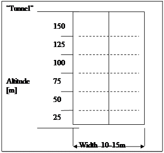
Fig.
6. Philosophy of flight corridors and flight trajectories
6.3. Functional
dependence on movement proposal
Flight trajectory is an
important parameter from all points of view on which probably depends also the
overall mass deployment of UAS into urban agglomerations.
The basic definition of flight
trajectory (FT) is designated as follow:
-
ZLT – engaged flight trajectory,
-
SNS – satellite navigation system,
-
Hb – altitude barometric,
-
HSNS – altitude,
-
Hra – radio altitude,
-
v – flying speed against the ground,
-
OP – orientation points,
-
OI – operation intensity.
FT = f (SNS, Hb, HSNS, Hra
,v, OP, OI) (2)
Achievement of this
functional dependence will fundamentally determine the use of UAS in urban
agglomerations in the future.
7. AN EXAMPLE OF FLIGHT CORRIDORS AND
FLIGHT TRAJECTORIES SELECTION
An example of flight corridors and flight
trajectories selection with labelling of applicable trajectories for flight
routes creation is illustrated in Frýdlant nad Ostravicí town in
the Moravian-Silesian Region.
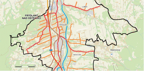
Fig. 7. Labelling of
applicable trajectories for flight routes creation in the framework of
Frýdlant nad Ostravicí town
For this purpose, we
used the accessible map (mapy.cz) with the possibility of routes network
labelling. This is easy to use as an example for illustration and creation of
flight corridors and flight trajectories. For simplicity, we assumed that
flight corridors must not be directly above roads, but beside roads, where
there is sufficient space. Selection of flight corridors must be approached with
sound knowledge of places and safety compliance.
Labelling of applicable
trajectories for flight routes creation in the framework of Frýdlant nad
Ostravicí town is illustrated in Figure 8. This figure represents the
selected flight routes network for the UAS operation. By the red and orange
colours are images of the main and minor flight routes above the roads. By the
brown colour is the image of the flight routes above the railways and by the
blue colour is the image above the watercourses.
The black line determines the borders of Frýdlant nad
Ostravicí town.
The network of selected
flight routes is dense in the centre of the town, less dense in the
surroundings parts of the town, Lubno and Nová Ves (Figure 8). There is
no intersection of flight routes and sectors designated for UAS operation. The
utility of these places is likely to increasefaster UAS overflights.
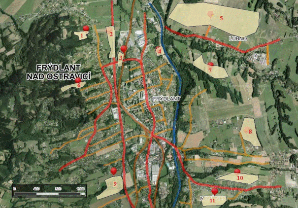
Fig. 8. Labelling of
flight corridors in the framework of Frýdlant nad Ostravicí town
in conjunction with overview of proposed corridors locations for UAS operation
Sample visualisation of
flight corridors is illustrated in Figure 9. Operation directions are opposite
on all minor routes: A, B and C. In the course of turning from middle route B
are UAS avoiding the horizontal plane with AIS inside routes A or C. These
measures alone increase the safety of the proposal.
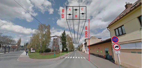
Fig. 9. Visualisation of
flight corridors in the framework of Frýdlant nad Ostravicí town
in conjuction with overview of proposed corridors locations for UAS operation
8. SAFETY RISKS OF UAS OPERATION IN AGGLOMERATIONS
For proposals finalisation of the possibility of UAS operation in agglomerations, the safety of these systems needs to be taken into consideration. A lot of potential risks originate during the use of UAS, hence the need for safety assurance. In spite of this, we were able to identify and anticipate in a great measure, eventual incidents or accidents.
One big advantage in the safety area is legislation. It requires the installation of Fail-Safe systems on almost all UAS (apart from UAS with maximum take-off weight (MTOW) up to 0,91 kg in recreational or sports operation). Fail-Safe systems are bound to improve with the development of new technologies. It is assumed that they would become the backbone of UAS safety operation assurance. It is worth mentioning that presently, these systems, for the most part, guarantee the UAS come back to its pilot-operator. Assuredly, we will have more sophisticated versions in the future, which will be able to perform autonomous operations with automatic compliance with minimum distances in the case of heavier UAS.
Single safety of UAS is therefore satisfactory, especially from the technical point of view. It is bright, with the increase of MTOW, the potential risk rate of operation is increased as well.
8.1. UAS operation safety in the framework of setting sectors
The setting sectors proposals in this paper, in general, is to serve UAS operation. Introduced sectors are according to current legislative/instruction, requirements for UAS operation with MTOW up to 7 kg. Nevertheless, this fact does not exclude the possibilities of a lighter UAS operation.
The reasons for minimum distances, which must be complied with during a UAS flight are apparent. The highest risk is the likely collision of UAS with persons. Considering the speed and weight of a flying UAS, this collision could have fatal results. Due to this fact, the conditions for distance minimum compliance appear logical and obligatory, it is also valid for possible UAS collision with buildings or other objects in the framework of towns (high voltage towers, antennas, trees). Probably, this does not present any direct threat to persons, however, the potential occasional financial damage is a high motivation for taking such relevant measurements. Setting of applicable corridors in compliance with the safety minimum distance is, therefore, a satisfactory prevention guarantee of the legislative/regulation standards.
The motivation for operation sectors setting was previously discussed in the paper. For now, it is needed to ensure the functioning of own sectors. Only publishing of borders and sectors size suitable for UAS operation does not ensure the continued serviceability of the sector. We must consider the possible accrued situations, which can threaten the serviceability of the sector. One of such possibilities is the movement of persons outside of the space. In this case, it is required to ensure minimum safety distance between a person and a UAS according to the instruction, which in this case represents 50 m and 100 m eventually. During movement of persons especially in the framework of smaller sectors, consequent considerable possible UAS operation may occur. Some sectors could become completely unusable. One of the possible solutions is the placing of operational central outside of the given sector. Suitable placing of central ensures satisfactory visibility over the whole sector. These sectors serve not only monitoring purposes except the sector is not in some way disrupted (that is, if restriction does not occur, leading to an impossible operation eventually), but also for UAS control. One operational central for monitoring operation and situation inside the sector is sufficient for nearby sectors. In the case of a large space, more operational central needs to be built. The advantages of this solution is that it solves other potentially limiting situations. These situations can be, for example, operation of other aircraft in the framework of the sector. Thanks to the operational central, it would be possible to ensure continual communication with close by operations, which would considerably increase the effectiveness of the proposed corridors.
8.2. Operation safety of UAS with weight up to 7 kg in the framework of a town
For the UAS with MTOW up to7 kg, the application of conditions concerning minimum distances is of no effect. In the current legislation, these minimum requirement is defined as “safe”. Thus, it depends first on the responsibility and experience of the UAS pilot. The obligatory UAS accounts are valid for all UAS in the profit, experimental or research operation and also for all systems with MTOW above 27 kg, where pilot registration is required too. For these cases, therefore, lies the responsibility of flight execution, pre-flight control and pilot preparation. According to the law, a pilot must use an unmanned system only for the purpose for which it was produced, designed and at the same time in such a way, that the technical parameters and UAS manner of use is in accordance with valid legislative requirements. In addition to this, the pilot-operator must record relevant flight information. Events of non-registered “UAS” pilots must not be reported. For this reason, it is impossible to elaborate on the statistics concerning operational safety of lighter UAS used for recreational and sport purposes.
8.3. Flight routes safety for UAS operation in the framework of a town
Bottom limit of flight route is designated at 100 m altitude above the ground. This altitude meets minimum distance for take-off /landing and proper distance away from persons according to current legislation for UAS with MTOW up to 7 kg. The variation from actual regulation is in minimum distances between UAS, buildings and urban areas. This discrepancy has been considered in draft only as a distinction between UAS flight altitude and height of the building.
UAS operation under the reduced minimum distance is of key importance for real use of UAS in towns. The proposed system takes into account the autonomous UAS operation according to advance planning trajectories. These trajectories are recorded into the navigation computer of the UAS.
Under the compliance with these conditions and assumptions, UAS could be in the framework of published routes to fly without pilot supervision and at night. The possibilities of cargo and package delivery are in these ways increased as well as overall ease of the proposed system.
9. CONCLUSIONS
Current conditions
(technical, legislative) do not allow mass usage of UAS in urban areas. It is
only a matter of years before they meet all required conditions for safety
movement for first single flights, then mass flights in densely populated urban
areas.
References
1. Balatě J. 2003. Automatické řízení. [In Czech: Automatic steering]. Praha: BEN. ISBN 80-7300-020-2.
2. Czech Republic. „Letecký předpis L2. Doplněk X - Bezpilotní letouny“. [In Czech: „L2 aeronautical regulation. Accessory X - Unmanned Aircraft“]. 2014. Available at: http://lis.rlp.cz/predpisy/predpisy/dokumenty/L/L-/data/effective/doplX.pdf.
3. Jacyna-Gołda Ilona, Mariusz Izdebski, Emilian Szczepanski. 2016. „Assessment of the method effectiveness for choosing the location of warehouses in the supply network”. Challenge of Transport Telematics, TST 2016. Communications in Computer and Information Science 640: 84-97.
4. Keller L. 2011. Učebnice pilota pro žáky a piloty všech druhů letounů a sportovních létajících zařízení, provozujících létání jako svou zájmovou činnost. [In Czech: Pilot textbook for pupils and pilots of all types of airplanes and flying sport equipment as their leisure activities]. Cheb: The World of Wings. ISBN 978-80-86808-90-1.
5. Kozakiewicz A., M. Kowalski. 2013. “Unstable operation of the turbine aircraft engine”. Journal of Theoretical and Applied Mechanics 51(3): 719-727.
6.
Martinec
F., I. Koblen, L. Socha, T. Lipták. 2017. “Unmanned aerial systems
movement in urban areas. New Trends in Civil Aviation”. In 19th Conference On New Trends in Civil
Aviation. Prague, Czech Republik, 7-8 December 2017. ISBN:
978-0-8153-7602-6 (Hbk+CD-ROM), ISBN: 978-1-351-23864-9 (eBook). P. 277-282.
7. Molnar Vieroslav, Gabriel Fedorko, Stanislav Honus, Lenka Girovska, Jan Lizbetin. 2018. “Selection and allocation of a warehouse linked to reloading terminal and seaport”. Nase More 65(4): 169-173.
8. Pech Z., V. Věk. 2006. Systémy řízení letu. [In Czech: Flight control systems]. Prague: Czech Technology - CTU Publishing House. ISBN 80-01-03374-0.
9. UAVs In The Lidar Applications Sector Increases Substantially. Dronezon.com. Available at: http://www.dronezon.com/learn-about-drones-quadcopters/uav-lidar-applications-services-technology-systems/.
Received 02.02.2019; accepted in revised form 17.05.2019
![]()
Scientific
Journal of Silesian University of Technology. Series Transport is licensed
under a Creative Commons Attribution 4.0 International License