Article citation information:
Urbanský, M. Comparison of piston and tangential pneumatic
flexible shaft couplings in terms of high flexibility. Scientific Journal of Silesian University of Technology. Series
Transport. 2018, 99, 193-203.
ISSN: 0209-3324. DOI: https://doi.org/10.20858/sjsutst.2018.99.18.
Matej URBANSKÝ[1]
COMPARISON OF PISTON AND TANGENTIAL PNEUMATIC FLEXIBLE
SHAFT COUPLINGS IN TERMS OF HIGH FLEXIBILITY
Summary. The
optimal tuning of mechanical systems in terms of torsional vibration magnitude
is a very important function in flexible shaft couplings. Therefore, a flexible
coupling with suitable dynamic properties, particularly dynamic torsional
stiffness, has to be carefully chosen for each specific application. The
current trend in the field of flexible shaft couplings, and the most noticeable
in the automotive industry, is the development and utilization of highly
flexible couplings, which means flexible couplings with a very low value of
relative torsional stiffness. The aim of this article is to introduce a new
type of flexible shaft coupling: a piston pneumatic flexible shaft coupling.
This coupling was developed to improve the properties of pneumatic flexible
couplings, especially the maximum angle of twist, in order to create a highly
flexible pneumatic coupling. For illustration purposes, the piston pneumatic
coupling is compared with the tangential pneumatic flexible shaft coupling of
Type 3-1/110-T-C in terms of high flexibility characteristics, whereby the
characteristic dimensions of both couplings are the same. Given that the piston
pneumatic coupling has not been manufactured to date, only a computational
model of this coupling was used. The results show that the design of the piston
pneumatic flexible shaft coupling combines the advantages of a highly flexible
and pneumatic shaft coupling.
Keywords: pneumatic flexible shaft couplings;
high-flexibility characteristics, comparison
1. INTRODUCTION
Nowadays, reducing vibration and noise in
machinery is a highly important task, mainly in terms of human health and the
lifetime and safety of machines, e.g., [2-6,8,9,13]. Flexible shaft couplings
are the most used machine parts for the flexible transmission of load torque
and mechanical energy in mechanical systems. Another highly important function
performed by them is the dynamic tuning of mechanical systems in terms of
torsional vibration magnitude. Therefore, a flexible coupling with suitable
dynamic properties, particularly dynamic torsional stiffness, has to be
carefully chosen for each specific application to ensure that dangerous
torsional vibration does not occur in a mechanical system, e.g., [8,9,12]. From the point of view of the
aforementioned dynamic tuning, the development and utilization of highly
flexible couplings are particularly advantageous and most noticeable in the
automotive industry nowadays (dual-mass flywheels). A highly flexible
coupling possesses a very low relative torsional stiffness k0. Relative torsional stiffness is expressed by the
following formula:
![]() , (1)
, (1)
which
is defined as the ratio of the nominal dynamic torsional stiffness of a
coupling kDN (at MN) to the nominal torque MN of a coupling. Common
flexible couplings have a relative torsional stiffness value in the range of
10÷30 rad-1. Shaft couplings marked as highly flexible
have a relative torsional stiffness value lower than 10 rad-1.
With the application of a highly flexible coupling in a mechanical system
(Coupling 2 in Fig. 1), the resonances from the individual harmonic
components of a torsional vibration excitation can be moved from the operating
speed (n) range (OSR) of the system
to the low-speed area, which is far enough under the idle operating speed nV, e.g., [6,9]. This
low-speed area can be quickly run across at the start-up of a mechanical
system, as shown in Campbell’s diagram of a mechanical system (Fig. 1),
where i represents the order of
the harmonic component of a torsional vibration excitation.
Nowadays, the flexible elements of flexible
shaft couplings are made of various materials. During the operation of
mechanical systems, rubber and plastic flexible elements experience fatigue and
ageing, while metal flexible elements of applied flexible couplings also
experience ageing and wear and tear [1,7,15]. Consequently, an applied flexible
coupling loses its original dynamic properties and thus its ability to carry
out important functions in a torsional oscillating mechanical system. Flexible
shaft couplings from the pneumatic flexible shaft couplings group (to which the
following couplings belong, according to the granted patents:
SK 288455 B6, SK 288344 B6, SK 288341 B6,
SK 278750 B6, SK 278653 B6, SK 278152 B6) are
able to facilitate the flexible transmission of mechanical energy without the
loss of their characteristic properties, because the gaseous medium in the
compression volume of couplings does not suffer from fatigue or ageing. The
main advantage of pneumatic couplings is the possibility to change their
torsional stiffness, which depends on the pressure value of the gaseous media.
Based on the aforementioned grounds, the development of flexible couplings,
with the benefits of both pneumatic and highly flexible couplings, is very
advantageous.
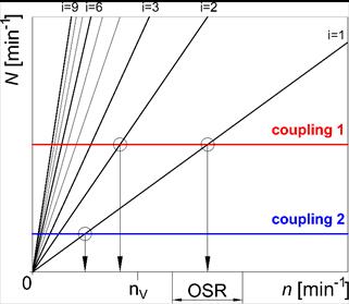
Fig. 1. Campbell’s
diagram of a mechanical system
From the point of view of physics, a flexible
coupling with a low torsional stiffness must have a large twist angle in order
to transmit a high load torque. This is the next prerequisite for creating a
highly flexible coupling. Therefore, the aim of this article is to introduce a
piston pneumatic flexible shaft coupling, which was developed to improve the
properties of pneumatic flexible couplings, especially the maximum angle of
twist, in order to create a highly flexible pneumatic coupling. For
illustration purposes, this coupling is compared with the tangential pneumatic
flexible shaft coupling of Type 3-1/110-T-C in terms of high-flexibility
characteristics, in which the characteristic dimensions of both couplings are
the same.
2. EXAMINED PNEUMATIC FLEXIBLE SHAFT
COUPLINGS
In the
following, the piston pneumatic flexible shaft coupling of Type 2-1/110-P-C[2]
(Fig. 2) is compared to the tangential pneumatic flexible shaft coupling
of Type 3-1/110-T-C[3]
(Fig. 3), manufactured by the FENA company in cooperation with our department. Both
couplings are designed to transfer load torque in one sense (their pneumatic
flexible elements must be pressed), have the same pitch diameter, DR=180 mm, and the same
outer diameter of pneumatic elastic elements, DE=110 mm. Given that the piston pneumatic coupling has
not yet been manufactured, only a computational model of this coupling was
used.
2.1. Piston pneumatic flexible shaft
coupling of Type 2-1/110-P-C
The piston
pneumatic flexible shaft coupling (Fig. 2) consists of a driving flange (1),
a driven flange (2), pneumatic flexible elements (4), curved hollow cases
(5), curved piston bodies (3), fastening flanges (6) and valves (7). The
compression volume of the coupling is created from two pneumatic flexible
elements (4), which are motionlessly placed in the hollow cases (5), which are
attached to the driven flange (2). The piston bodies (3) are attached to the
driving flange (1). The pneumatic flexible elements (4) are inflated to the
required overpressure of gaseous media through the valves (7), and the basic
position of the piston bodies and the driving flange (1) in relation to the
driven flange (2) is herewith defined (Fig. 2a). The transmission of load
torque causes a twist in the driving flange (1) in relation to the driven
flange (2), and the piston bodies (3) are therefore pushed into the pneumatic
flexible elements (4) so that the piston bodies (3) are coated with the
pneumatic flexible elements (4) (Fig. 2b). The design of the coupling allows for
a maximum angle of twist of 76°.
|
|
|
|
a) |
b) |
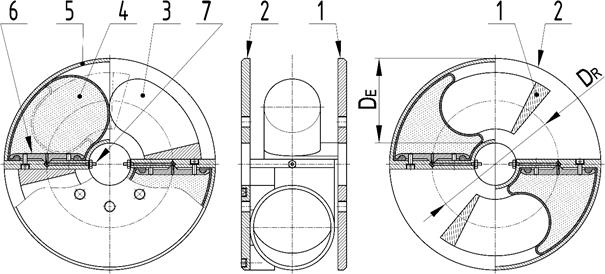
Fig. 2. The piston pneumatic flexible
shaft coupling of Type 2-1/110-P-C: a) unloaded state; b) partially
loaded state
The compression of gaseous media in
the pneumatic flexible elements (4) is proportional to the load, resulting in
the flexible transmission of load torque in mechanical systems.
2.2. Tangential pneumatic flexible shaft
coupling of Type 3-1/110-T-C
By this coupling (Fig. 3), load
torque is transmitted flexibly from the driving flange (1) to the driven flange
(2) by the compression volume of the coupling. The compression volume is
created from three pneumatic flexible elements (3), which are tangentially
positioned around the perimeter of the coupling and completely interconnected
with the hoses (4). The gaseous medium streams into the compression volume of
the coupling through the quick-acting pneumatic fitting (5). The design of the
coupling allows for a maximum angle of twist of 15°.
|
|
|
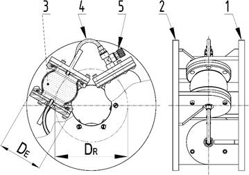
Fig. 3. The tangential
pneumatic flexible shaft coupling of Type 3-1/110-T-C
3. DETERMINING THE BASIC
CHARACTERISTIC PROPERTIES OF THE COUPLINGS
3.1. Dependence of
pressure in the pneumatic couplings on their twist angle
As for
pneumatic flexible shaft couplings, load torque is transmitted flexibly from
the driving flange to the driven flange by pneumatic flexible elements. As the
transmission of load torque causes a twist in the driving flange in relation to
the driven flange, the compression volume of a pneumatic coupling is
compressed. The compression of gaseous media in the pneumatic flexible elements
is proportional to the load.
|
|
|
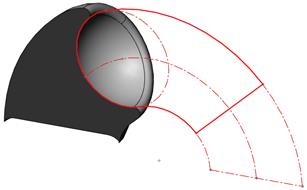
Fig. 4. The principle of modelling
the air volume deformation caused by the piston body, as a section view |
In Fig. 5,
we can see the dependencies of air overpressure ppS in the compression volume of the pneumatic couplings
on their angle of twist φ.
Initial air overpressure values (at φ=0º)
in the couplings were ppS0=100÷600 kPa.
For the tangential coupling, the dependencies in Fig. 5b were measured and the
maximally allowed ppS
value was 800 kPa [10]. For the piston coupling, the dependencies in Fig.
5a were computed as follows:
1. The dependence of the air volume V on the twist angle φ was determined using 3D CAD
software (Fig. 4)
2. The dependence of the air overpressure ppS in the pneumatic coupling
on the twist angle φ was
determined by considering isothermal compression using the following formula:

![]() , (2)
, (2)
where pa is the atmospheric pressure (pa=101,325 Pa).
|
|
|
|
a) |
b) |
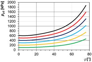
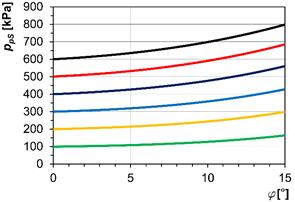
Fig. 5. The
air overpressure ppS in
the couplings, which is dependent on the twist angle φ at various values of ppS0:
a) piston coupling of Type 2-1/110-P-C; b) tangential coupling of
Type 3-1/110-T-C
3.2. Static load characteristics
According
to the standard [16], the static load characteristic of a flexible coupling is
the dependence of the coupling twist on load torque during slow change in the
load torque. The loading and unloading of a coupling should be performed
smoothly at a constant speed <0.002 rad/s-1.
Five cycles of loading and unloading should be performed and the static
characteristic should be obtained as the loading part of the fifth cycle. The
coupling should be loaded up to the maximum static load torque MSmax, which can be defined,
for example, according to the maximum twist angle of a flexible coupling. The
condition is not to damage the coupling. In Fig. 6, we can see the static
characteristics of both couplings at initial air overpressure values in their compression volume ppS0=100 ÷ 600 kPa. The
static characteristics of the tangential pneumatic coupling (Fig. 6a) were
determined in the laboratory of our department and the static characteristics
of the piston pneumatic coupling (Fig. 6b) were computed from the equality of
the works of the gaseous medium and torque:
![]() . (3)
. (3)
|
|
|
|
a) |
b) |
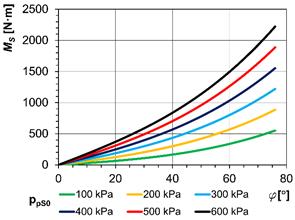
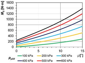
Fig. 6. The static load
characteristics at various values of ppS0:
a) piston coupling of Type
2-1/110-P-C; b) tangential coupling of Type 3-1/110-T-C
The
static load characteristics of both couplings are slightly non-linear and can
be described by cubic equations in the form, MS=a0·φ + a3·φ3. The coefficients a0 and a3
(Tab. 1) were determined by the method of least squares.
Tab. 1.
The coefficients a0 and a3 of static load characteristic equations
|
Piston coupling 2-1/110-P-C |
Tangential coupling
3-1/110-T-C |
||||
|
ppS0 |
a0 |
a3 |
ppS0 |
a0 |
a3 |
|
100 kPa |
820.0 |
3,858.9 |
100 kPa |
168.4 |
140.5 |
|
200 kPa |
1,434.8 |
5,178.2 |
200 kPa |
338.4 |
187.0 |
|
300 kPa |
1,959.6 |
7,718.2 |
300 kPa |
508.4 |
233.6 |
|
400 kPa |
2,506.6 |
9,851.8 |
400 kPa |
678.3 |
280.1 |
|
500 kPa |
3,030.4 |
11,563.2 |
500 kPa |
848.3 |
326.6 |
|
600 kPa |
3,532.3 |
12,414.5 |
600 kPa |
1,018.3 |
373.1 |
According
to the standard [16], the nominal torque MN
of a flexible coupling can be determined as the third of its maximum static
load torque MSmax. In Fig.
7, we can see the MSmax
and MN dependencies on
initial air overpressure ppS0 for the piston pneumatic coupling
(Fig. 7a) and tangential pneumatic coupling (Fig. 7b).
|
|
|
|
a) |
b) |
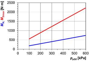
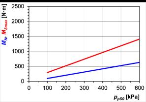
Fig. 7. Maximum static
torque MSmax and nominal
torque MN, which are
dependent on initial air overpressure ppS0:
a) piston coupling of Type 2-1/110-P-C; b) tangential coupling of
Type
3-1/110-T-C
3.3. Static torsional stiffness
The
dependence of the static torsional stiffness kS of a flexible coupling on the twist angle φ can be computed by deriving the equation of the static
characteristic of a flexible coupling.
In Fig.
8, we can see the static
torsional stiffness kS,
which is dependent on the twist angle φ
of the couplings at initial air overpressure values in the pneumatic couplings ppS0=100÷600 kPa
for the piston pneumatic coupling (Fig. 8a) and tangential pneumatic
coupling (Fig. 8b).
|
|
|
|
a) |
b) |
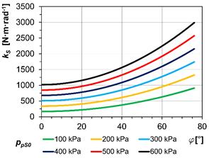
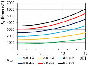
Fig. 8. The dependence of
the static torsional stiffness kS
on the twist angle φ at various
values of ppS0:
a) piston coupling of Type 2-1/110-P-C; b) tangential coupling of
Type 3-1/110-T-C
4. HIGH-FLEXIBILITY CHARACTERISTICS
OF THE COUPLINGS
In order to compute the relative torsional
stiffness values k0 of the
pneumatic couplings, the values of the dynamic torsional stiffness kDN of the pneumatic
couplings at the nominal torque MN
need to be determined. According to the research, the kDN values of the pneumatic couplings can be determined
by the following formula:
![]() , (4)
, (4)
where kSN is the value of the static torsional stiffness of
the pneumatic coupling at the nominal torque MN at a certain value of initial air overpressure in the
pneumatic coupling in the range of ppS0=100÷600 kPa.
Finally,
the relative torsional
stiffness k0 of the
couplings can be determined according to Eq. (1). In Fig. 9, we can see the
relative torsional stiffness k0,
which is dependent on
initial air overpressure in the pneumatic couplings ppS0=100÷600 kPa for the piston pneumatic
coupling (Fig. 10a) and the tangential pneumatic coupling (Fig. 10b).
|
|
|
|
a) |
b) |
Fig. 9. The relative
torsional stiffness k0,
which is dependent on initial air overpressure ppS0: a) piston coupling of Type 2-1/110-P-C;
b) tangential coupling of Type 3-1/110-T-C
As we can see from Fig. 9, the
piston pneumatic flexible coupling of Type 2-1/110-P-C meets the requirements
for high flexibility in the whole range of the initial air overpressure ppS0 within its compression
volume, while the tangential pneumatic flexible coupling of Type
3-1/110-T-C can be marked as highly flexible at approximately ppS0>150 kPa.
5. CONCLUSION
With the transfer of load torque by
the compression volume of pneumatic flexible shaft couplings filled with a
gaseous medium, we achieve the compression of the medium proportional to load.
This is how the continuous flexible load torque transmission in the driving and
driven machine system is characterized. Gaseous media throughout their lifetime
are not subject to ageing, meaning that pneumatic couplings do not lose their
initial positive dynamic properties.
From the above-presented graphs and
tables, we can see that the Type 2-1/110-P-C piston pneumatic coupling, in
comparison with the Type 3-1/110-T-C tangential pneumatic flexible coupling,
offers the following advantages:
·
It
has lower values of torsional stiffness (Fig. 8), while its transmission
ability is higher (Figs. 6-7), thanks to its large maximum twist angle. The
piston pneumatic coupling is able to transmit about 160% larger torque by the
same pitch diameter DR.
The outer diameter of both couplings is approximately the same too.
·
According
to Fig. 9, both compared pneumatic couplings are highly flexible. The piston
coupling has much smaller values of relative torsional stiffness (Fig. 9),
which means that it has a higher flexibility than the tangential coupling.
·
The
design of the piston coupling allows for MS=0
at φ=0 (Fig. 6); in other words,
the piston coupling do not have initial torsional rigidity unlike the
tangential coupling.
Meanwhile, the piston coupling has
the following disadvantages:
· An unconventional pneumatic flexible
element needs to be developed and manufactured for the piston pneumatic
coupling.
· To achieve the presented
transmission ability (Figs. 6-8), the piston coupling needs to work with
relatively high levels of overpressure in its compression space (Fig. 5).
Both compared couplings are designed to transfer load torque in one
sense, while their pneumatic flexible elements are pressed. Therefore,
neglecting the influence of the rubber-cord coating of pneumatic flexible
elements [14], the difference between static and dynamic torsional stiffness in
the pneumatic couplings is mainly caused by a polytrophic process in their
compression volume under dynamic load [11]. Under dynamic load, pneumatic
flexible elements do not generate too much heat, unlike the flexible elements
made of rubber and plastic [7]; therefore, the pneumatic couplings can work
with large amplitudes of twist at high frequencies.
References
2.
Czech P. 2013.
“Intelligent Approach to Valve Clearance Diagnostic in Cars”.
Activities of Transport Telematics. TST 2013. Communications in Computer and Information Science 395: 384-391.
DOI: https://doi.org/10.1007/978-3-642-41647-7_47.
3.
Czech P., Mikulski
J. 2014. “Application of Bayes Classifier and Entropy of Vibration
Signals to Diagnose Damage of Head Gasket in Internal Combustion Engine of a
Car”. Telematics - Support For Transport. TST 2014. Communications in Computer and Information Science 471: 225-232.
DOI: https://doi.org/10.1007/978-3-662-45317-9_24.
4.
Figlus
Tomasz, Jozef Gnap, Tomas Skrucany, Branislav Sarkan, Jozef Stoklosa. 2016.
„The Use of Denoising and Analysis of the Acoustic Signal Entropy in
Diagnosing Engine Valve Clearance”. Entropy
18(7). Article Number: 253.
5.
Figlus
Tomasz, Stefan Liscak. 2014. „Assessment of the vibroactivity level of SI
engines in stationary and non-stationary operating conditions”. Journal Of Vibroengineering 16(3):
1349-1359.
6.
Grega Robert,
Jozef Krajňák, Lucia Žuľová, Gabriel Fedorko,
Vieroslav Molnár. 2017. “Failure analysis
of driveshaft of truck body caused by vibrations”. Engineering Failure Analysis 79: 208-215. ISSN: 1350-6307.
DOI: 10.1016/j.engfailanal.2017.04.023.
8.
Homišin
Jaroslav. 2016. “Characteristics of
pneumatic tuners of torsional oscillation as a result of patent
activity”. Acta Mechanica et
Automatica 10(4): 316-323. ISSN: 1898-4088.
DOI: 10.1515/ama-2016-0050.
9.
Homišin
Jaroslav, Peter Kaššay. 2014. “Optimal tuning of
torsional oscillating mechanical systems”. In: Proceedings of the 54th International Conference of Machine Design
Departments: Modern Methods of Construction Design: 63-69. Department of
the Design of Machine Elements and Mechanisms, Technical University of Liberec,
Czech Republic. 10-12 September 2013. Hejnice, Czech Republic. ISBN:
978-3-319-05203-8. DOI: 10.1007/978-3-319-05203-8_9.
12. Kyslan K., M. Rodič, Ľ. Suchý,
Ž. Ferková, F. Ďurovský. 2017. “Industrial controller-based dynamometer with dynamic
emulation of mechanical loads”. Electrical
Engineering 99(4): 1245-1254. ISSN: 0948-7921.
DOI: 10.1007/s00202-017-0626-z.
13. Liptai Pavol, Marek Moravec, Ervin Lumnitzer, Marcela
Gergeľová. 2017. “Proposal of the
sound insulating measures for a vibrational sorter and verification of the
measured effectiveness”. Advances
in Science and Technology-Research Journal11 (3): 196-203. ISSN:
2299-8624. DOI: 10.12913/22998624/76068.
14. Medvecká-Beňová Silvia, Ľubica
Miková, Peter Kaššay. 2015. “Material
properties of rubber-cord flexible element of pneumatic flexible
coupling”. Metalurgija
54(1): 194-196. ISSN: 0543-5846.
15. Samociuk W., Z. Krzysiak, G. Bartnik, A. Skic, S.
Kocira, B. Rachwal, H. Bakowski, S. Wierzbicki, L. Krzywonos. 2017. „Analysis
of explosion hazard on propane-butane liquid gas distribution stations during
self tankage of vehicles”. Przemysl
Chemiczny 96(4): 874-879. DOI: 10.15199/62.2017.4.29.
This paper
was written within the framework of the KEGA 041TUKE-4/2017 grant project
“Implementation of New Technologies Specified for Solving Questions
Concerning the Emissions of Vehicles and Their Transformation in Educational
Processes in Order to Improve the Quality of Education”.
This article
was created with support from the project for PhD students and young
researchers project entitled “Solution of a Control System Element for
Mechanical Systems’ Continuous Tuning”.
Received 24.02.2018; accepted in revised form 16.05.2018
![]()
Scientific Journal of
Silesian University of Technology. Series Transport is licensed under a Creative
Commons Attribution 4.0 International License