Article
citation information:
Shpachuk, V., Chuprynin, A.,
Suprun, T., Kovalenko, A. Multiple-factor analysis of the dynamic
interaction between railroad cars and joint irregularity. Scientific Journal of Silesian University of Technology. Series
Transport. 2018, 99, 183-192.
ISSN: 0209-3324. DOI: https://doi.org/10.20858/sjsutst.2018.99.17.
Vladimir SHPACHUK[1],
Aleksandr CHUPRYNIN[2],
Tatiana SUPRUN[3],
Andriy KOVALENKO[4]
MULTIPLE-FACTOR
ANALYSIS OF THE DYNAMIC INTERACTION BETWEEN RAILROAD CARS AND JOINT IRREGULARITY
Summary. Mechanical models of “railroad
car-track” transport system for each phase of motion are developed.
Particularities of dynamic interaction between the four-axle car and the track
are studied by considering four phases of motion over joint irregularity.
Methods for solving differential equations of the discrete-continuous system
fluctuation are developed. Numerical analysis is used to determine deflections
of the trailing rail under the first sleeper for each phase of motion depending
on motion phases, and car load and speed.
Keywords: railway rolling stock;
four-axle car; track; ballast; joint irregularity; trailing rail; facing rail
1. INTRODUCTION
The
issues of optimizing performance characteristics and developing efficient
design solutions, which enhance reliability and increase the longevity of rail
transport, are becoming of crucial importance nowadays under conditions of
rapid development in transportation technologies. The operating life of railway
rolling stock and track structure depends on the interaction between elements,
which is affected by mechanical, design and geometrical characteristics [4,5,15].
The
operating performance of the track under railway rolling stock depends on the
type of rail fastening, the stiffness of the track structure elements and
operational conditions. Reducing the parameters of dynamic interaction between
the railroad car and the track, in particular, at the joints, allows for the
transition to durable, reliable, comfortable and fast rail transport.
The
ballast draft under sleepers in rail joint areas is the most informative index
of mechanical interaction in the “wheel-rail” system [15]. It is at
rail joints that the rail is typically exposed to the largest impact load,
which leads to rail creeping and sagging, and the emergence of gapless and
elongated joints. Thus, elastic and permanent residual deformations of the
ballast under rail supports determine the operation and service life of the
track.
2. LITERATURE REVIEW AND RESEARCH
OBJECTIVE
According to the analysis of the research
dealing with issues of mechanical interaction between the four-axle car and the
track [15],
insulated rail joints are the weakest link in the examined system. Besides,
having to take into account phases of the car motion over joint irregularity is
emphasized, as well as characteristics of the ballast stiffness [7,17]. In
addition, an emphasis is placed on issues relating to the combined action of
railway rolling stock and the track, which determines the particularities of
their static and dynamic interaction [10] while the car passes over the
joints.
As
different factors, which change during the operation of the track, stipulate
the application of the multiple-factor model, research that focuses on
improving existing models of interaction between the car and the track
structure is modern and of topical interest.
The
load of rolling stock elements and track structure determine the parameters of
longevity [188],
durability and stiffness of the track [8]. These parameters have an impact on
operation and service life. The experience of operating rail transport shows [145] that
indices of reliability and longevity in the “car-track” mechanical
complex greatly depend on particularities of interaction between the track and
the rolling stock and operational conditions of the system above. Besides, the
interaction above affects the system ability to withstand the destructive
action of emerging impact and vibration loads [8], which are of a cyclically
recurrent nature.
To
analyse dynamic interaction between rolling stock and track structure, it is
necessary to solve several interrelated problems, namely, static, impact and
dynamic problems. Particular attention is being paid to the issues above, and
new sufficient research in this field is being undertaken.
When
we consider topical research in this field, when concerning the track, much of
it focuses on particular aspects of design and operation. To ensure the
application of a complex approach, it is necessary to use a generalized tool
integrating different aspects of design and operational conditions, which
allows for the complex assessment of track dynamics [9]. Several models have
been developed to analyse and predict structural behaviour. The traditional
approach is to apply the finite element method, involving commercially
available software packages [16], which requires considerable financial costs
in the course of designing. Besides, closed-source code does not facilitate the
analysis of all interaction aspects [14].
The
finite element method is also applied to the ballast model [11], which involves
transmitting load from the wheel to the soil where the track is built [13].
Thus, some countries are using reinforced concrete when building roadways [2], but
the cost of their construction is significantly higher compared to the standard
ballast track design. Another approach is to increase ballast thickness, which
leads to decreasing deflection under the load and causes lower stress in the
soil. This improves the performance and lifespan of the track [1]. The
large number of suggested design solutions prompts several questions as to the
efficient ways in which to solve the set tasks. The analysis of modern research
demonstrates that the application of a multiple-factor system analysis, which
takes into account the phases of motion of the car over joint irregularity and
characteristics of track stiffness, represents a current trend in the
developing theory of mechanical interaction between the four-axle car and the
track. Thus, we can state the need to create an adequate and easy-to-use model
of the train-track interaction and the corresponding methods of their dynamic
interaction analysis, where the railroad car is considered as a
multidimensional discrete system and the track structure is viewed as a
continual system.
The
purpose of the present research is to study the dynamic interaction between the
railroad car and the track structure to improve parameters of the
discrete-continuous system by means of rational choice and optimization of the
parameters of its components.
Thus, the objectives of the study are as follows: to
develop a complex model and method of analysis of the
interaction between the four-axle car and the track on the basis of a systemic
approach and general correlations of the dynamics, taking into account phases
of car motion over joint irregularity; to apply methods of numerical analysis
in order to determine and analyse the interaction between the elements of the
transport systemic discrete-continuous mechanical complex; and to determine new
patterns of mechanical interaction between the four-axle car and the track when
the four-axle car passes over joint irregularity with respect to motion phases
in order to develop efficient design solutions.
3. MODEL AND METHODS FOR
ANALYSING THE DYNAMIC INTERACTION BETWEEN THE TRACK AND THE RAILROAD CAR
A
multiple-factor dynamic discrete-continuous model of the four-axle car is
analysed in the present research. The four-axle car can be represented by
either a tram car, or a passenger or freight wagon. The model takes into
account the design parameters and load of the vehicle, connection conditions of
the trailing and facing rails through a rail joint plate, and ballast
stiffness. The car passing over joint irregularity is considered for all phases
of motion. Thus, in the first phase, all the wheel sets are positioned on the
trailing rail; in the second phase, three wheel sets remain; in the third
phase, there are only two wheel sets; and, in the fourth phase, there is only
one wheel set. In the present paper, a mechanical schematic, using the example
of the first phase of motion, is given in Fig. 1.
Fig. 1. Schematic for passing over joint irregularity
The
label descriptions are as follows: 1) a railroad car of the transportation
vehicle; 2-5) corresponding wheel of the wheel set; 6-7) central suspension of
the car; 8) facing rail; 9) trailing rail; 10) elastic elements of the ballast
under sleepers; 11) elastic element that simulates stiffness of the trailing
rail at the end.
Calculation
of the interaction at other phases differs according to the number of wheels on
the facing and trailing rails. The results of the study concerning other phases
of motion are presented as characteristic curves and finite analysis. The
suggested integrated approach provides for the consecutive solution of
interrelated tasks, as presented in the structural and logical scheme
in Fig. 2, which implements the suggested scheme of a consecutive static
and dynamic calculation method.
Block 1 - static calculation. Here
mechanical characteristics of railway rolling stock and the track
and the car load, as well as phases of the car passing and calculating error,
are defined. As a result, we obtain the size of the step upstairs and the
stiffness of the rail at the end.
Block 2 - calculation of the impact
interaction of the wheel and the facing rail. At this stage,
mechanical characteristics of the car, trolleys, wheels and rail are specified,
as well as the size of the step upstairs, design speed and stiffness of the
rail at the end, which allows us to define the after-collision speed of the
joint motion of the wheel and the facing rail.
Block 3 - dynamic calculation. At
this stage, mechanical properties of the examined system, initial conditions,
after-collision speed, static deflection of the facing rail and the phase of
the car passing over the joint irregularity are defined. As a result of the
calculations, we obtain the maximum deflections of the facing rail under the
first sleeper.
By
conducting static calculations, we can define rail stiffness at the end as one
of the elastic supports (Block 1 [15]). In total, static calculations
enable us to define the deflections of the trailing and facing rails
(transferred to Block 3), as well as the size of the step (transferred to Block
2). In Block 2, the impact interaction between the wheel and the facing rail is
considered. In addition to motion parameters (speed and car load), these
calculations define the size of the step. On examining the impact interaction,
we can define the vertical speed of the wheel and the facing rail. These values
are transferred to Block 3, in which the oscillations of the facing rail,
during the phase of increasing its deflection under the first sleeper, are
calculated. The data on static and impact interaction are used in this boundary
value problem. Static deflection of the facing rail and its vertical speed, as
calculated in Blocks 1 and 2, respectively, are used as initial conditions.
Fig.
2. Structural scheme for the calculation method
3.1. Impact interaction
Let us consider the
impact interaction of the wheel and the facing rail in accordance with the
structural scheme in Fig. 2. At the beginning of the calculations, the
mechanical parameters of the transportation vehicle, and the track and connection
conditions
of the rails are defined as well as the results of the static calculations of
the size of the step upstairs (Block 1 in Fig. 2). At this stage, the
parameters of the impact momentum, to which the facing rail is exposed during
its impact interaction with the wheel, are defined using the change-of-momentum
theorem of the system [15]. Further, the assumption is that, on
collision, the facing rail is bent at the same curve as in the case of static
load. Then, the motion speed of the rail after collision at the contact point,
depending on the load and phase of the car motion over joint irregularity, is
defined. The obtained data are transferred to Block 3 (Fig. 2).
3.2. Dynamic interaction
The calculated
mechanical schematic of dynamic interaction for the facing rail during the
first phase of the car motion is shown in Fig. 3.
The label
descriptions are as follows: с1, b1 - suspension stiffness and
damping coefficient; с2,
b2 - ballast stiffness and
damping coefficient; сp.k - stiffness of the rail at its
end (calculated
in Block 1 in Fig. 2);
m1, m2 - reduced masses of the
wheel and the car, taking into account the load; у1; у2 - displacement of
reduced mass of the wheel and the car; and li (і=1-24) - geometrical coordinates of the elastic supports.
While
calculating the deflections of the discrete-continuous system, mechanical and
geometrical characteristics, static deflections and after-collision speed for
the facing rail are defined. Differential equations for
oscillations in the mechanical schematic in Fig. 3 are given below [37]:
 (1)
(1)
where:
δ(х) - impulse function; w
- rail deflection; ![]() - the coordinate of the
relevant rail;
- the coordinate of the
relevant rail; ![]() - the coordinate of the
relevant wheel on the facing rail; K -
the number of wheels on the facing rail corresponding to the phase of motion; F, ρ
- the cross-sectional area and density of the rail material; and
- the coordinate of the
relevant wheel on the facing rail; K -
the number of wheels on the facing rail corresponding to the phase of motion; F, ρ
- the cross-sectional area and density of the rail material; and ![]() - bending stiffness.
- bending stiffness.
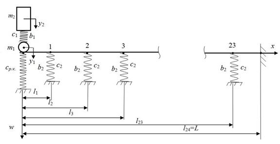
Fig. 3. Calculated mechanical
schematic of dynamic interaction for the facing rail during the first phase of
the car motion
The
system deflections are viewed as a superposition of the first five eigenmodes. Using a model with
energy dissipation is undoubtedly feasible under these conditions. However, the
damping properties of the ballast are neglected in most calculations due to the
fact that the rail deflection is only considered during the phase when it increases.
The solution to the
system (1) is performed using the Fourier method for the separation of
variables [3] and the Laplace-Carson
transform. In the case above, the solution to the problem with
the facing rail oscillation is reduced to a superposition of eigenmodes. As a result, the rail
deflection, when considering the sprung mass and non-zero initial conditions
taken from the static rail deflection (Block 1 in Fig. 2) and after-collision
speed (Block 2 in Fig. 2), can be represented by the following expression [3,6]:
w(t,x)=![]() . (2)
. (2)
where: Ds -
coefficients from mode orthogonality [145] when
jointly considering the after-collision speed of the rail with the wheel, ![]() ;
; ![]() - eigenmode and natural
oscillation frequencies of the system;
- eigenmode and natural
oscillation frequencies of the system; ![]() -
dissipation factors of the appropriate form;
-
dissipation factors of the appropriate form; ![]() - reduced mass of the rail; and
- reduced mass of the rail; and ![]() - reduced resistance factor.
- reduced resistance factor.
All the
above allows us to define the function of the deflections, which is used to
obtain the maximum deflection under the first sleeper (х=l1)
of the facing rail at the initial time t=0. When
increasing the time gap, the deflection starts to grow until it reaches its
maximum value. After that, the deflection starts to decrease, which confirmed
that the searching for its maximum values has ended.
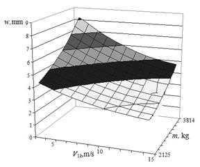
4. RESEARCH RESULTS
In accordance with the suggested model, a
numerical analysis of the parameters of dynamic interaction between a four-axle
car and the track in the area with isolated joint irregularity of the “gap”
type has been performed. Calculations have been made on the basis of the
variation in operational factors, namely, car load and speed during the
relevant phases of the car motion over irregularity, as shown in Figs. 4-7. As
a result, we have obtained correlations of maximum deflection under the first
sleeper by taking into account the fastening of the trailing and facing rails
to rail joint plates, and the geometrical and mechanical
characteristics of the rails, plates, sleepers and ballast.
The
analysis has been performed in accordance with the calculation pattern in Fig.
2, which has allowed us to define the function of the deflections by solving
the differential equations for discrete-continuous system fluctuation (1) in
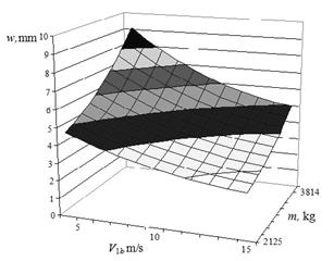
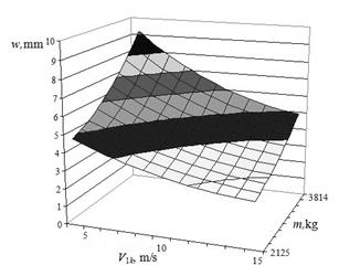
the case of mechanical energy dissipation (2). The
results obtained show that the biggest deflections occurred during the second
and third phases of the car motion over joint irregularity.
|
Fig. 4. Facing rail deflection during the
first phase of motion |
Fig. 5. Facing rail deflection during the
second phase of motion |
|
Fig. 6. Facing rail deflection during the
third phase of motion |
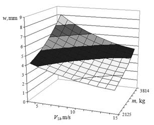
Fig. 7. Facing rail deflection during the fourth phase of
motion |
The calculations have
been performed using the geometrical and mechanical characteristics of the P-65
rail, with the T-3 tram as an example [1],
where: the modulus of elasticity of the rail material is Е=2.6·1011 N/m2; the moment
of inertia of the rail cross section, relative to the neutral axis, is J=3573 cm4; the
suspension and ballast stiffness are с1=4.225·105 N/m, с2=1·108 N/m;
and the resistance factors for suspension and ballast are b1=24·103 kg/s,
b2=60·103 kg/s. The
car’s empty weight was reduced to one wheel (=m1+m2=2,125 kg)
and the maximum weight of a loaded car, i.e., with 193 passengers (m=m1+m2=3814 kg;
m1=1,100 kg).
Meanwhile, ![]() =150 kg represents the reduced
mass of the rail, which corresponds to the operational conditions and the design
characteristics of the railway rolling stock, and the track and joint plates of
real objects.
=150 kg represents the reduced
mass of the rail, which corresponds to the operational conditions and the design
characteristics of the railway rolling stock, and the track and joint plates of
real objects.
5. CONCLUSIONS
The numerical
calculation results for the parameters of the dynamic car-track interaction in
the area of joints are given, with reference to operational, mechanical and
geometrical factors. The relevant models are also offered. The research allows
us to define new patterns of interaction between the four-axle car and the
track while passing over joint irregularity, as well as improving the operational
performance and characteristics of the car and the track structure by means of
rational choice and optimization. The findings can be applied when developing
design solutions in order to improve track joints, defining operation modes of
tram cars depending on the state of the track, and developing experimental and
theoretical complexes for the purpose of researching, calculating and
optimizing the parameters of rail transport knots.
References
1.
Allan James. 2012. “Soil
mechanics of high speed rail tracks”. In: First Civil and Environmental Engineering Student Conference:
206-212. 25-26 June 2012. Imperial College London.
3.
Бабаков
И.М. 1968. Теория
колебаний.
Москва:
Наука. [In Russian:
Babakov I. M. 1968. Theory of
Oscillations. Moscow: Nauka.]
4.
Bakowski H. J. Piwnik. 2016.
„Quantitative and qualitative comparison of tribological properties of
railway rails with and without heat treatment”. Archives Of Metallurgy
And Materials 61(2): 469-474. DOI: 10.1515/amm-2016-0037.
5.
Bakowski H., A. Posmyk, J. Krawczyk. 2011.
„Tribological properties of rail steel in straight moderately loaded
sections of railway tracks”. Archives Of Metallurgy And Materials 56(3):
813-822. DOI: 10.2478/v10172-011-0090-0.
6.
Черногоров Е.П.
2013. Колебания
механических
систем.
Челябинск:
Ю-УГУ. [In Russian:
Chernogorov E. P. 2013. Fluctuations
of Mechanical Systems. Chelyabinsk: South Ural State
University.]
7.
Domin R., I. Domin, G. Cherniak, A.
Mostovych, V. Konstantidi, P. Gryndei. 2016. “Investigation of the some
problems of running safety of rolling stock on the Ukrainian railways”. Archives Of Transport 40(4): 15-27.
8.
Gursky V., I. Kuzio. 2016.
“Strength and durability analysis of a flat spring at vibro-impact
loadings”. Eastern-European Journal
of Enterprise Technologies 5/7(83): 4-10. ISSN: 1729-3774. DOI:
10.15587/1729-4061.2016.79910.
10.
Лазарян В. А.
1964. Динамика
вагонов.
Устойчивость
движения и
колебания.
Москва:
Транспорт. [In Russian: Lazaryan V. A. 1964. Car Dynamics: Stability of Movement and
Fluctuations. Moscow: Transport.]
12.
Nuzzolo A., Comi A. 2015. “Modelling the demand for rail
in an urban context: some methodological aspects”. Transport\Transporti Europei 57(3).
13.
Rose J.G., P.F. Teixeira, N.E.
Ridgway. 2010. “Utilisation of asphalt/bituminous layers and coatings in
railway trackbeds”. In: 2010 Joint
Rail Conference: 239-255. 27-29 April 2010. Urbana, Illinois. ISBN: 978-0-7918-4906-4.
15. Shpachuk V., A.
Chuprynin, T. Suprun, A. Garbuz. 2018. “A multifactor analysis of the
rail transport car that passes over a joint unevenness with respect to the
phases of its motion”. Eastern-European
Journal of Enterprise Technologies 1/7(91): 55-61. ISSN: 1729-3774. DOI:
10.15587/1729-4061.2018.121584.
16. Srihari, P.,
Azad, D., Sreeramulu, D. 2014. “Optimization of rail inserts
using finite element analysis”. International
Journal of Engineering, Science and Technology 6(2): 65-75. ISSN:
2141-2839. DOI:
http://dx.doi.org/10.4314/ijest.v6i2.5.
17. Вериго М. Ф.,
А. Я. Коган. 1986. Взаимодействие
пути и
подвижного
состава.
Москва:
Транспорт. [In Russian: Verigo M. F., A.Ya.
Kogan. 1986. Interaction of Track
and Rolling Stock. Moscow: Transport, 559.]
Received 20.02.2018; accepted in revised form 17.05.2018
![]()
Scientific
Journal of Silesian University of Technology. Series Transport is licensed
under a Creative Commons Attribution 4.0 International License