Article
citation information:
Medvecká-Beňová,
S. Designing
pitch curves of non-circular gears. Scientific
Journal of Silesian University of Technology. Series Transport. 2018, 99, 105-114. ISSN: 0209-3324. DOI: https://doi.org/10.20858/sjsutst.2018.99.10.
Silvia MEDVECKÁ-BEŇOVÁ[1]
DESIGNING PITCH
CURVES OF NON-CIRCULAR GEARS
Summary. The paper examines the design and generation of gear
drives with non-circular gears. Gearings with a changing transmission gear
ratio are used for the purposes of practical experimentation, even though
“standard” gearings with a constant transmission gear ratio are
used more often. In this paper, the author presents the design for the shape of
a pitch outline for a specific requirement, that is, continuous change in gear
ratio during one rotation. The gearing is designed such that the pitch curve is
composed of an ellipse. The article also presents some kinematic properties of
the designed non-circular gearing.
Keywords: gear; non-circular;
ellipse; pitch outline; variable transmission ratio
1. INTRODUCTION
Gearboxes belong to the most used transmission mechanisms. The history
of gears is probably as old as civilization itself. The earliest description of
gears was written in the fourth century BCE by Aristotle, who wrote that the
“direction of rotation is reversed when one gear wheel drives another
gear wheel”. In practice, the most commonly used “standard”
toothed gears are characterized by a constant gear number and circular wheel
shape. Non-circular gears are not well known, even though the idea behind them
originates from the pioneers of engineering thought. For example, such gears
were sketched by Leonardo da Vinci (Fig. 1) [1], while, in the late 19th
century, Franz Reuleaux ordered a series of non-circular gear models from the
Gustav Voigt Mechanische Werkstatt in Berlin to help with the study kinematics.
These historical gears comprised simplified tooth shapes and, for this reason,
the meshing conditions were not always correct.
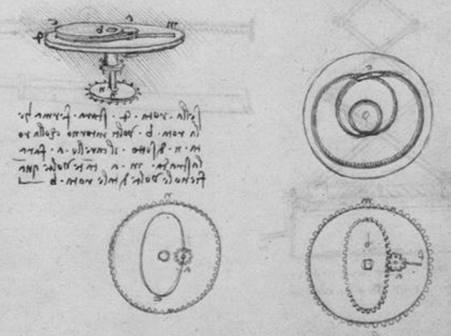
Fig. 1. Sketch by Leonardo da Vinci [1]
Non-circular gears are
presented as a curiosity from the gear industry history, due to their complex
design and manufacturing difficulties. Nowadays, performance modelling and
simulation software, advanced CNC machine tools and non-conventional manufacturing
technologies enable non-circular gear design and manufacture.
As mechanisms used to
generate variable motion laws, in comparison with cams, linkages, variable
transmission belts, Geneva mechanisms and even electrical servomotors,
non-circular gears are remarkable due to their advantages, such as the ability
to produce variable speed movements in a simple, compact and reliable way, the
lack of gross separation or decoupling between elements, fewer parts in the
design phase, and the ability to produce high strength-to-weight ratios [2-4].
The applications of
non-circular gears include textile industry machines, for improving machine
kinematics resulting in process optimization [5,6], window shade panel drives,
for introducing vibrations that interfere with natural oscillations and
cancelling them out [7], high-torque hydraulic engines for bulkhead drives
[8-11], and mechanical presses, for optimizing work cycle kinematics. They are
also used as high-power starters, mechanical systems (providing progressive
torque for easier start-ups of machines, where progressive torque helps to
overcome the start-up inertia) and forging machines (optimizing the work cycle
parameters and reducing pressure dwell time). The use of non-circular gears in
industry certifies their effective performance, while prompting new ideas for
improved working conditions. Non-circular gears are also used on oval gear
flowmeters [12], which are categorized as positive displacement flow technology
devices. Positive displacement flow technology allows for precise flow
measurements of most clean liquids, regardless of media conductivity.
The generation of
non-circular gears is usually developed from a hypothetical basis, such as the
law of driven gear motion, variation in the gear transmission ratio, and the
design of the driving gear pitch curve [13-14]. The studies for the design and
manufacture of non-circular helical gears are highly limited.
The first step in the non-circular
gear virtual design process is the generation of the conjugate pitch curves,
starting from a predesigned law of motion for the driven element or a
predesigned geometry for the driving gear pitch curve. The current paper is
dedicated to this problem.
2. conditions OF proper meshing
The industry standard
involute tooth shape has been chosen for use in non-circular gears. Thus, the
existing involute gearing standards and methods can be adopted and applied. The
design of correct meshing must be based on the basic conditions that are
imposed on gearing. The tooth profiles, which form a shape bond, must have a
designed continuous meshing. Otherwise, in order to transmit a uniform rotary
motion from one shaft to another by means of gear teeth, the normals to the
profiles of these teeth at all points of contact must pass through a fixed
point (point P in Fig. 2.) in the
common centre line (O1O2
in Fig. 2.) of the two shafts. The fixed point is, of course, the pitch point;
and, for involutes, the normals (line n
in Fig. 2.) fall onto the line of action. The instantaneous normals to the
profiles of these teeth at all points of contact must pass through a fixed
point in the common centre line of the two shafts to transmit any rotary motion
from one shaft to another by means of gear teeth t. The pitch curves (k1 and k2 in Fig. 2.) correspond to the pitch circles in
“standard” circular gears.

Fig. 2. Condition of the
meshing of non-circular gears
Fig. 3 depicts
non-circular gears as two rollers rolling together without slippage, provided
there it is no addendum modification and the nominal axle distance (parameter a in Fig. 3.) is used. Roll lines (pitch
curves) are divided into z parts,
which are p long, where z is the gear’s number of teeth
and p is the pitch. The gear is
represented by two pitch curves k1
and k2 with centres in
points O1 and O2. The variable pitch curve
radii, r1(φ) and r2(φ), of the
non-circular gears are determined by the required course of the transmission
ratio i and therefore the ram
kinematics:
![]() (1)
(1)
where ω1(φ) and ω2(φ)
are the angular velocity functions for Gears 1 and 2, respectively.
With a given constant
centre distance:
![]() (2)
(2)
the transmission
function ψ´(φ)
describes the relation between the pitch curves of the non-circular gears. In
the case of an aperiodic non-circular gear, angular positions of the members
are limited [17-19]. Usually, a specific ratio function is used, for example, a
logarithmic function.
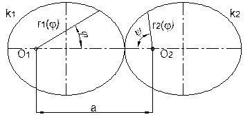
Fig. 3. Example of
non-circular pitch curves
3. Eccentric Elliptical Gearing
3.1. Characteristic of non-circular
gearing
The generation of this non-circular gear
was developed from a hypothetical basis, such as the law of driven gear motion,
variation in the gear transmission ratio and the design of the driving gear
pitch curve. This model of non-circular gear was designed for a variable
transmission ratio in the range u=0.25 to 4.0. This transfer should be formed by
two identical wheels with the number of teeth z1=z2=40 and gearing module mn=4 mm, where distance a=160 mm, and for one direction of
rotation.
3.2. Design of pitch curves
The first step in the non-circular gear
design process is the generation of the pitch curves, starting from a
predesigned law of motion for the driven element or a predesigned geometry for
the driving gear pitch curve. For a non-standard gearing, an eccentric
elliptical gear drive with a continuously changing transmission gear ratio was
applied; that is, the ellipse was used as the pitch curve (Fig. 4.). For the
given distance, the pitch ellipse had a large half-axis ae=80 mm, which is half of the axial distance. The
position of ellipse focus was determined by considering the desired
continuously changing transmission gear ratio. For the given variable
transmission ratio in the range u=0.25 to 4.0, the position of the ellipse
focal point (centre point O of
rotation) is determined by the ratio lengths x1: x2, which are equal to 1:4. The second
half-axis, be=64 mm, is
determined by the distance from the focus point ae=80 mm for the transmission ratio u=1.
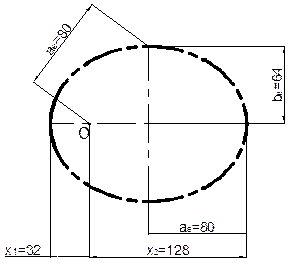
Fig. 4. Pitch ellipse for gear
ratio u=0.25 to 4
In this case, one of the conditions of a
correct mesh is that the measurements of the pitch on the ellipse pitch must be
kept constant. A geometric separation of the pitch ellipse into 40 identical
sections (the number of teeth z1=z2=40)
is mathematically much more difficult than in the case involving standard
gear pitch circles.
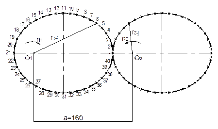
Fig. 5. Design of the non-circular
pitch curves
Fig. 5 presents the
pitch ellipses of a designed eccentric elliptical gear drive with a
continuously changing transmission gear ratio for given parameters. Torque
transmission ensures shape-bonding between the meshing gears. The gearing
consists of two identical gears. The toothed number is shown for the drive
wheel; for the driven wheel, this numbering is the same. Wheels are designed
for only one direction of rotation. The pitch ellipses must meet the condition
that, for each tooth, the sum of the radii is equal to the axial distance
(Tab. 1.).
![]() (3)
(3)
where r1-i and
r2-j are the radii of mesh
points.
3.3. Kinematic properties of
non-circular gearing
In pursuit of kinematic ratios for the
proposed gearings, we assumed the right mesh conditions. Kinematic conditions
were processed for the drive wheel (centre of rotation at point O1) and the driven wheel
(with the centre of rotation at point O2).
On the relevant graph, the two gears are shown in a state of kinematic
dependence (initially, on the horizontal axis of the wheel teeth). In Tab. 1, the
dimensions of the spacing radii at the individual points of contact are
designated as r1-i,
respectively, while r2-j,
where Index 1 applies to the drive
wheel, Index 2 for the driven wheel,
and Index i or j corresponds to the order number of the engaging tooth (Fig. 5) at
one turn of the drive and driven wheel.
Tab.
1.
The kinematic properties of elliptical gearing
|
Meshing teeth input - output |
Radius of mesh points |
Centre distance a=r1-i + r2-j (mm) |
Transmission ratio ui=r2-j/r1-i |
Rotational speed ω2i=ω1/ui
(s-1) |
|
|
r1-i (mm) |
r2-j (mm) |
||||
|
1-21 |
128 |
32 |
160 |
0.250 |
400 |
|
02-20 |
127.25 |
32.75 |
160 |
0.257 |
388. 550 |
|
03-19 |
125.08 |
34.92 |
160 |
0.279 |
358. 190 |
|
04-18 |
121.67 |
38.33 |
160 |
0.315 |
317. 428 |
|
05-17 |
117.24 |
42.76 |
160 |
0.365 |
274.181 |
|
6-16 |
112.03 |
47.97 |
160 |
0.428 |
233.542 |
|
07-15 |
106.24 |
53.76 |
160 |
0.506 |
197.619 |
|
08-14 |
100.01 |
59.99 |
160 |
0.600 |
166.711 |
|
09-13 |
93.5 |
66.5 |
160 |
0.711 |
140.601 |
|
10-12 |
86.79 |
73.21 |
160 |
0.844 |
118.549 |
|
11-11 |
80 |
80 |
160 |
1 |
100 |
|
12-10 |
73.21 |
86.79 |
160 |
1.185 |
84.353 |
|
13-9 |
66.5 |
93.5 |
160 |
1.406 |
71.123 |
|
14-8 |
59.99 |
100.01 |
160 |
1.667 |
59.984 |
|
15-7 |
53.76 |
106.24 |
160 |
1.976 |
50.602 |
|
16-6 |
47.97 |
112.03 |
160 |
2.335 |
42.819 |
|
17-5 |
42.76 |
117.24 |
160 |
2.742 |
36.472 |
|
18-4 |
38.33 |
121.67 |
160 |
3.174 |
31.503 |
|
19-3 |
34.92 |
125.08 |
160 |
3.582 |
27.918 |
|
20-2 |
32.75 |
127.25 |
160 |
3.885 |
25.737 |
|
21-1 |
32 |
128 |
160 |
4 |
25 |
|
22-40 |
32.75 |
127.25 |
160 |
3.885 |
25.737 |
|
23-39 |
34.92 |
125.08 |
160 |
3.582 |
27.918 |
|
24-38 |
38.33 |
121.67 |
160 |
3.174 |
31.503 |
|
25-37 |
42.76 |
117.24 |
160 |
2.742 |
36.472 |
|
26-36 |
47.97 |
112.03 |
160 |
2.335 |
42.819 |
Fig. 6 represents the course of a
continuously changing gear ratio in one mesh generated by an elliptical gear,
which continuously varies in the range from u=0.25
to u=1.0 until u=4.0, and back. Thus, the gear ratio changes over the duration of
one revolution. A gear ratio value that is less than 1.0 signifies that this is an overdrive, while a gear ratio value
greater than 1.0 signifies a speed
reduction.
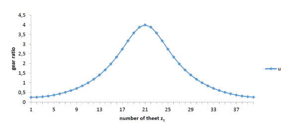
Fig. 6. Transmission gear ratio
Fig. 7 shows the progress of the meshing
radii at the individual points of contact, designated as r1-i, respectively, while r2-i, where Index 1
applies to the drive wheel, Index 2
to the driven wheel, and Index i or j corresponds to the order number of the
tooth.
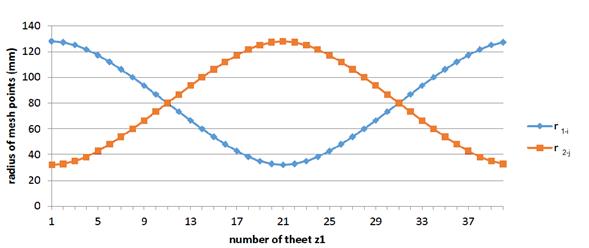
Fig. 7. Radius of the mesh points
The rotational speed of the drive wheel
gear and the driven wheel gear is constant for standard spur gears. For the
designed elliptical gearing with variable transmission, the angular velocity of
the driven wheel is not constant but changed according to the continuous
changing of the gear ratio. This is shown in Fig. 8, where the angular velocity
is on the drive wheel (ω1=100
s-1) and the driven elliptical wheel (ω2i).
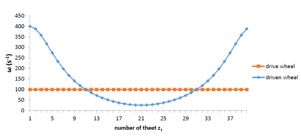
Fig. 8. Rotational speed
in non-circular gearing
3.4. Modification the pitch ellipse
when changing the gear ratio
For changes in gear ratio, for example, the variable
transmission ratio, in the range u=0.5
to 2, the modification of the pitch
ellipse is necessary. Fig. 9 presents the shape of the pitch ellipse for the
non-circular gear, which is defined by the number of
teeth z1=z2=40
and gearing module mn=4 mm,
where the distance a=160 mm and the
gear ratio is u=0.5 to 2.
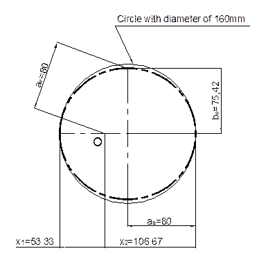
Fig. 9. Pitch ellipse for the gear
ratio u=0.5 to 2
The position of ellipse focus is
determined by considering the desired continuously changing transmission gear
ratio. For the gear ratio in the range u=0.5
to 2, the position of the ellipse
focal point (centre point O of
rotation) is determined by the ratio lengths x1: x2, which are equal to 1:2. The second
half-axis be=75.42 mm is
determined by the distance from the focus point ae=80 mm for the transmission ratio u=1. The position of the pitch ellipse focus is consistent with the
variable gear ratio.
4. CONCLUSION
This article describes how to optimize the
design of pitch curves of non-circular gears for given parameters. Non-circular
gearing consists of two identical gear wheels. For a non-standard gearing, an
eccentric elliptical gear drive with a continuously changing transmission gear
ratio was applied. The kinematic properties of this gearing are different from
the properties of standard circular gears, i.e., spur gears. Thus, the gear
ratio changes over the duration of one revolution.
Non-circular gears synthesize the
advantages of circular gears and cam mechanisms, as well as offer a combination
of high output power and excellent accuracy with continuously variable transmission.
Non-circular gears have been applied to construction machinery, machine tools,
and the automotive, aerospace and other fields.
References
1.
Walter
Isaacson. 2017. Leonardo da Vinci.
Simon & Schuster. ISBN: 1-4744-6676-7, 599.
2.
David
Dooner, Seireg Ali. 1995. The Kinematic
Geometry of Gearing. John Wiley & Sons. ISBN: 978-0-471-04597-7, 472.
3.
Kowalczyk
Leon, Stanislaw Urbanek. 2003. “The geometry and kinematics of a toothed
gear of variable motion”. Fibres & Textiles in Eastern Europe
11, 3(42): 60-62.
4.
Zhang
Xin, Shouwen Fan. 2016. “Synthesis of the steepest rotation pitch curve
design for noncircular gear”. Mechanism
and Machine Theory 102: 16-35. DOI: 10.1016/j.mechmachtheory.2016.03.020.
5.
Mundo
Domenico. 2006. “Geometric design of a planetary gear train with
non-circular gears”. Mechanism and
Machine Theory 41: 456-472.
6.
Figlus
Tomasz, Marcin Stańczyk. 2014. “Diagnosis of the wear of gears in
the gearbox using the wavelet packet transform”. Metalurgija 53(4):
673-676. ISSN: 0543-5846.
7.
Doege,
Eckart, John Meinen, Tobias Neumaier. 2001. “Numerical design of a new
forging press drive incorporating non-circular gears”. Journal
of Engineering Manufacture 215:
467-471.
8.
Tong
Shihhsi, Yang Daniel. 1998. “Generation of identical noncircular pitch
curves”. Journal of Mechanical
Design 120: 337-341.
9.
Bošanský
Miroslav, Miroslav Vereš. 2012. Neštandardné
ozubené prevody. Bratislava: STU v Bratislave. ISBN:
978-80-227-3717-5.
10.
Litvin
Feonid et al. 2008. “Design and investigation of gear drives with
non-circular gears applied for speed variation and generation of
functions”. Computer Methods in
Applied Mechanics and Engineering 197: 3783-3802.
11.
Kapelevich
Alexander. 2000. “Geometry and design of involute spur gears with
asymmetric teeth”. Mechanism and Machine Theory 35(1):
117-130.
12.
Liu,
Youyu. 2015. “Study of optimal strategy and linkage-model for external
non-circular helical gears shaping”. Proceedings
of the Institution of Mechanical Engineers Part C: Journal of Mechanical
Engineering Science 229(3): 493-504.
13.
Dyakov
I., O. Prentkovskis. 2008. “Optimization problems in designing
automobiles”. Transport 23(4):
316-322.
14.
Rincon
Femandez, Fernando Viadero, 2013. “A model for the study of meshing
stiffness in spur gear transmissions”. Mechanism and Machine Theory 61: 30-58.
This paper was written within the framework
of the following grant projects: “VEGA 1/0290/18 - Development of New
Methods of Determination of Strain and Stress Fields in Mechanical System
Elements by Optical Methods of Experimental Mechanics”; “KEGA
041TUKE-4/2017 - Implementation of New Technologies Specified for the Solution
of Questions Concerning Emissions of Vehicles and Their Transformation in the
Educational Process in Order to Improve Quality of Education”; and
“APVV-16-0259 - Research and Development of Combustion Technology Based
on Controlled Homogenous Charge Compression Ignition in Order to Reduce
Nitrogen Oxide Emissions of Motor Vehicles”.
Received 11.02.2018; accepted in revised form 19.05.2018
![]()
Scientific
Journal of Silesian University of Technology. Series Transport is licensed
under a Creative Commons Attribution 4.0 International License