Article
citation information:
Kaššay, P. Effect of torsional
vibration on woodchip size distribution. Scientific
Journal of Silesian University of Technology. Series Transport. 2018, 99, 95-104. ISSN: 0209-3324. DOI: https://doi.org/10.20858/sjsutst.2018.99.9.
Peter KAŠŠAY[1]
EFFECT OF
TORSIONAL VIBRATION ON WOODCHIP SIZE DISTRIBUTION
Summary. Nowadays, there is increasing demand for the use of
renewable energy sources such as woodchips. One of the important qualitative
parameters of woodchips is the size distribution. The aim of this article is to
determine the effect of a woodchipper disc’s torsional vibration on the
evenness of woodchip length, as well as propose a mathematical solution to this
problem by assuming one harmonic component of disc speed and the uniform feed
of chipped material. The presented mathematical solution can be used to
determine the unevenness of woodchip length when the parameters of torsional
vibration are known.
Keywords: mathematical model;
size distribution; torsional vibration; uneven chip length; woodchips
1. INTRODUCTION
Nowadays, there is increasing
demand for the use of renewable energy sources such as woodchips. One of the
important qualitative parameters of woodchips is size distribution. From the
usability point of view, it is important to achieve homogeneous properties of
woodchips because heterogeneous material can cause problems with bridging over
openings [6], high emissions from burning [9,10], storing and drying [7].
Woodchip size distribution is
affected by dimensional inaccuracies in the woodchipper, feeding speed,
geometry of the cutting tool and the properties of the chipped material [1,2].
We assume that woodchip size
distribution may be also affected by torsional vibration of the
woodchipper’s disc, especially in the case of the inappropriate tuning of
the mechanical system drive. The purpose of this paper is to mathematically
express the influence of the torsional vibration of the disc chipper on the
unevenness of woodchip length.
2. KINEMATICS OF THE
WOODCHIPPER DISC
The use of a disc
chipper, whose principle is illustrated in Fig. 1, is considered. The
disc (1) rotates with the mean angular speed w
[rad/s-1]. The disc has z
knives (2) applied uniformly to the face of the disc. All consecutive knives
are rotated relative to one another by the pitch angle jN. Material with a
constant width (3) is fed to the knives at the uniform feeding speed vf [mm·s-1],
the value of which must be adjusted so that the chip is cut before touching the
disc face in order to avoid energy loss from friction [1].
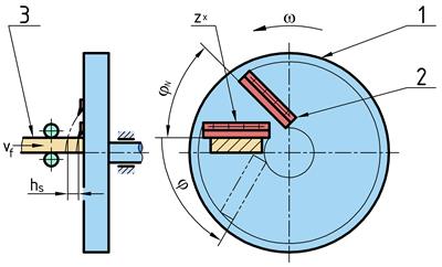
Fig. 1. Scheme of the disc chipper
The length of chip hs [mm] depends on the disc
angular speed w, the feeding speed vf [mm·s-1]
and the number of knives z. The disc
angle is labelled as j [rad]. The time course
of the disc angle is shown in Fig. 2. The disc rotates at
the mean angular speed w and simultaneously
performs a harmonic torsional vibration with the angular frequency i·w.
The nominal cutting frequency with the constant angular speed w is equal to z·w.
The disc angle,
according to Fig. 1Fig. 2, can generally be
expressed by the following equation:
|
|
(1) |
where:
t - time [s]
j0 - disc angle amplitude
[rad]
i - order of torsional
vibration [-]
g -
phase of torsional vibration [rad]
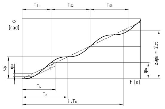
Fig. 2. Time course of the disc angle
The angular velocity ![]() [rad·s-1] is obtained as a time
derivation of the disc angle (1):
[rad·s-1] is obtained as a time
derivation of the disc angle (1):
|
|
(2) |
For the limit disc angle
amplitude j0=F0, the stopping of the
disc is considered. For larger amplitudes, the angular velocity of the disc can
reach negative values. By fitting zero angular velocity for t=0 and g=0
into Eq. (2), we obtain the value
of limit disc angle amplitude:
|
|
(3) |
The relative size of
torsional vibration k [-] can be
expressed with the ratio of the disc angle amplitude j0 to the limit disc angle
amplitude F0 as:
|
|
(4) |
where k ![]() .
.
According to Fig. 2, pitch angle jN [rad] can be computed
as:
|
|
(5) |
In turn, the disc’s angle of
rotation during one period of torsional vibration can be computed as:
|
|
(6) |
Then, the nominal period of cutting
TN [s] can be computed
from the nominal cutting frequency:
|
|
(7) |
In turn, the period of torsional
vibration TK [s] can be
computed from the frequency of torsional vibration:
|
|
(8) |
The woodchip length hS [mm] can be determined
from the feeding speed vf and time between the moments of touching
the chipped material by two consecutive knives TS [s] corresponding to the pitch angle jN, as shown in Fig. 1 and Fig. 2, by expression:
|
|
(9) |
The nominal woodchip
length hN [mm] can be
computed as:
|
|
(10) |
As the times TS are not constant and differ from nominal cutting
period TN (see Fig. 2), the woodchip length
will also not be constant. Therefore, we can say that torsional vibration may
cause woodchip length unevenness.
3. COMPUTING WOODCHIP
LENGTH UNEVENNESS
Woodchip length
unevenness can be expressed by the proportional chip length n [-], as a ratio of the woodchip
length hs (9 to the nominal woodchip
length hN (10:
|
|
(11) |
The relationship in (11 shows that the
proportional chip length n depends on times TS and TN.
Next, a parameter of the
frequency ratio h [-], representing the
ratio of the frequency of torsional vibration to the cutting frequency, is
introduced:
|
|
(12) |
To simplify the
derivation of relationships, we introduce the dimensionless parameters of
torsional vibration and woodchip length. The dimensionless representation of
torsional vibration is shown in Fig. 3, where dimensionless
time s is related to the period of
torsional vibration TK:
|
|
(13) |
and a dimensionless rotation angle u is related to the disc’s angle
of rotation during one period of torsional vibration jK:
|
|
(14) |
Dimensionless woodchip
length S will be related to the
nominal period of torsional vibration TK:
|
|
(15) |
The nominal
dimensionless woodchip length can be obtained as a ratio of nominal period of
cutting TN (7 to the period of
torsional vibration TK (8, which will be equal to
frequency ratio h, see relationship (12:
|
|
(16) |
The dimensionless
amplitude of torsional vibration u0
can be obtained as a ratio of torsional vibration amplitude j0, expressed in the
formula in (4, to the disc’s
angle of rotation during one period of torsional vibration jK (6:
|
|
(17) |
Then, the proportional
woodchip length can be computed from dimensionless values S and SN as:
|
|
(18) |
The woodchip length will
reach the limit values when it is located symmetrically around points where the
actual speed of the disc is at its maximum (Fig. 3a) or minimum (Fig. 3b).
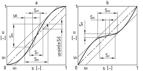
Fig. 3. Dimensionless representation of
torsional vibration
The actual value of the
length of each woodchip will lie between these limit values. The range (0; 1)
in Fig. 3, on the horizontal
axis, corresponds to one period of torsional vibration TK, while, on the vertical axis, it corresponds to the
disc’s angle of rotation during one period of torsional vibration jK.
According to Fig. 3, we can express the nominal
dimensionless woodchip length as:
|
|
(19) |
and the envelope of limit values of
dimensionless woodchip length as:
|
|
(20) |
By modifying Eq. (19, we obtain a formula for
the limit values of dimensionless woodchip length:
|
|
(21) |
Now, we can express the
limit values of the proportional woodchip length as the ratio of S1,2 from Eq. (20 to SN from Eq. (16, and by using the
formula in (17 as u0:
|
|
(22) |
By introducing
substitutions into the formula in (22, the limit values of
the proportional woodchip length n1,2 are finally obtained as:
|
|
(23) |
where:
d0 - the limit envelope value of the
proportional woodchip length:
|
|
(24) |
x1,2 - the limit envelope
value of proportional woodchip length:
|
|
(25) |
However, we need to
express the value of x1,2 depending on SN. Therefore, the inverse function to (19 should be fit into Eq. (25. The graphical solution
is shown in Fig. 4. The functions x1,2 are periodic, with the
period of frequency ratio h=2. As the shape of x1 and x2 functions are identical, and the phase shift between
them is equal to 1, only a half-period is shown in Fig. 4. We also do not need to
know which line exactly represents x1 and x2, because we only need
to know that the actual proportional woodchip length will lie between these
limit values.
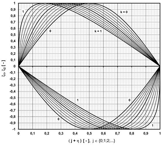
Fig. 4. Limit envelope value of the proportional woodchip
length
Fig. 5 shows the limit values
of the proportional woodchip length, according to the formula in (23, depending on frequency
ratio h, in terms of different
relative sizes of torsional vibration k.
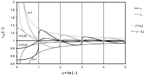
Fig. 5. Limit values of the proportional woodchip length
4. DISCUSSION
According to Fig. 5, the influence of the
following torsional vibration parameters on woodchip length unevenness can be
stated thus:
(1)
Frequency ratio h
If the frequency ratio
between the cutting frequency and the torsional vibration frequency is an
integer, unevenness in woodchip length cannot arise.
This can be accomplished
by using a mesh drive with a proper gear ratio (e.g., gear, timing belt, chain
drives). With a friction drive, due to slippage, this goal cannot be
accomplished.
The frequency ratio is
influenced by the following parameters:
(1a)
Frequency of torsional vibration excited by the woodchipper’s disc
The frequencies of the
torsional vibration harmonic components excited by the disc will be an integer
multiple of the number of knives. This means that the unevenness of woodchip
length, due to the woodchipper’s disc excitation, cannot theoretically
arise.
(1b)
Frequency of torsional vibration excited by the drive
This includes harmonic
components excited by the engine (most likely, a piston combustion engine) or
fluctuations in the gear ratio (e.g., due to the use of a cardan joint, shaft
misalignment) [4]. For these influences,
it is advisable to keep the engine torque constant (use of electric motor) or
to maximize the order of the main harmonic component (choosing a piston engine
with a larger number of cylinders).
(1c)
Frequency of self-excited vibration
The frequency of
self-excited vibration is close to the natural frequency of the mechanical
system [3]. In this respect, it
is advantageous to have the frequency of self-excited torsional vibration
(natural frequency) as high as possible. As such, it is necessary to avoid an
integer ratio of natural frequency to cutting frequency in order to avoid
resonance in the system [11].
(1d)
Number of knives
Woodchip length
unevenness reaches the highest values in the case of low values of the
frequency ratio, i.e., for low frequencies of torsional vibration and a high
number of knives.
Therefore,
it is advantageous to choose as low a number of knives as possible.
(2) Size
of torsional vibration amplitude
Woodchip length
unevenness increases depend on the rising torsional vibration amplitude.
Therefore, it is the best to keep the amplitude as low as possible. The highest
value of vibration amplitude occurs in the case of resonance, i.e., when the
frequency of the exciting torque is equal to the mechanical system’s
natural frequency. This can be avoided by the proper tuning of the
system’s dynamic parameters (i.e., torsional stiffness, mass moment of
inertia, damping coefficient) [5].
4. CONCLUSION
The method presented in
this paper is suitable for determining woodchip length unevenness caused by
torsional vibration of the disc chipper. In order to use this method, it is
necessary to know the parameters of torsional vibration (frequency and
amplitude), which can be obtained theoretically by dynamic analysis or by
measurement.
In the future, it will
be necessary to examine the realistically achievable range of woodchip length
unevenness caused by torsional vibration, based on the dynamic analysis of
currently produced disc chippers.
References
1.
Abdallah
Rami, Sébastien Auchet, Pierre Jean Méausoone. 2011. “Experimental study about the effects of
disc chipper settings on the distribution of wood chip size”. Biomass and Bioenergy 35(2): 843-852.
ISSN: 0961-9534. DOI: 10.1016/J.BIOMBIOE.2010.11.009.
2.
Abdallah
Rami, Sébastien Auchet, Pierre Jean Méausoone. 2014. “A dynamic measurement of a disc chipper
cutting forces”. Biomass and
Bioenergy 64: 269-275. ISSN: 09619534. DOI: 10.1016/J.BIOMBIOE.2014.02.033.
4.
Grega
Robert, Jozef Krajňák, Lucia Žuľová, Gabriel
Fedorko, Vieroslav Molnár. 2017. “Failure
analysis of driveshaft of truck body caused by vibrations”. Engineering Failure Analysis 79:
208-215. ISSN: 1350-6307. DOI: 10.1016/j.engfailanal.2017.04.023.
5.
Homišin
Jaroslav, Matej Urbanský. 2015. “Partial results of extremal control of
mobile mechanical system”. Diagnostyka
16(1): 35-39. ISSN: 1641-6414.
6.
Jensen
Peter Daugbjerg, Jan Erik Mattsson, Pieter D. Kofman, Achim Klausner. 2004. “Tendency of wood fuels from whole trees,
logging residues and roundwood to bridge over openings”. Biomass and Bioenergy 26(2): 107-113.
ISSN: 0961-9534. DOI: 10.1016/S0961-9534(03)00101-6.
7.
Kristensen
Erik Fløjgaard, Pieter D Kofman. 2000. “Pressure resistance to air flow during
ventilation of different types of wood fuel chip”. Biomass and Bioenergy 18(3): 175-180. ISSN: 0961-9534. DOI:
10.1016/S0961-9534(99)00089-6.
8.
Mickevicius
T., S. Slavinskas, S. Wierzbicki, K. Duda. 2014. „The effect of
diesel-biodiesel blends on the performance and exhaust emissions of a direct
injection off-road diesel engine”. Transport
29(4): 440-448. ISSN: 1648-4142.
10.
Paulrud
Susanne, Calle Nilsson. 2004. “The
Effects of particle characteristics on emissions from burning wood fuel
powder”. Fuel 83(7-8): 813-821.
ISSN: 0016-2361. DOI: 10.1016/J.FUEL.2003.10.010.
11. Wilson Wiliam Ker. 1967. Practical Solution of Torsional Vibration
Problems – Volume 1.
London: Chapman & Hall Ltd.
This
paper was written within the framework of the KEGA 041TUKE-4/2017 grant project
“Implementation of New Technologies Specified for Solving Questions
Concerning the Emissions of Vehicles and Their Transformation in Educational
Processes in Order to Improve the Quality of Education”.
This
article was created with support from the project for PhD students and young
researchers project entitled “Solution of a Control System Element for
Mechanical Systems’ Continuous Tuning”.
Received 14.02.2018; accepted in revised form 11.05.2018
![]()
Scientific
Journal of Silesian University of Technology. Series Transport is licensed
under a Creative Commons Attribution 4.0 International License