Article
citation information:
Wieczorek, A.N. Analysis of lubrication conditions for
angle planetary gearboxes applied in mining scraper conveyors. Scientific Journal of Silesian University of
Technology. Series Transport. 2018, 98, 191-199. ISSN: 0209-3324. DOI:
https://doi.org/10.20858/sjsutst.2018.98.18.
Andrzej N. WIECZOREK[1]
ANALYSIS OF LUBRICATION CONDITIONS FOR ANGLE PLANETARY GEARBOXES APPLIED
IN MINING SCRAPER CONVEYORS
Summary. The paper presents calculations of the
relative oil film value for the meshing of angle planetary gearboxes used in
mining scraper conveyors. Calculating the value of this parameter was made
using methodology that was compliant with ISO/TR 15144-1: 2014 (E). As a result
of the analysis, it was found that exploitation of mining gears takes place
under boundary or mixed lubrication conditions, with oil viscosity and surface
roughness having a significant influence on these conditions.
Keywords: scraper conveyor, planetary
gear, wear, lubrication
1. INTRODUCTION
The main purpose of
lubrication [1] is to transform the friction of external contacting elements
into the friction inside the lubricant layer. The formation of a relatively
permanent layer that separates mating surfaces may be caused by physisorption
of polar particles on friction surfaces, chemisorption of small boundary layers
generated as a result of tribochemical processes, or by hydrodynamic or
elasto-hydraulic effects.
With respect to elements
of gearboxes, such as gear wheels, it is essential to create, under conditions
of elasto-hydraulic lubrication (a diagram of the elasto-hydrodynamic contact
zone of involute profile teeth, along with a specification of the actual
surface deformation, is presented in Figure 1), a layer that separates mating
surfaces in order to ensure their high operating durability. The thickness of
this layer is characterized by a certain parameter, i.e., the minimum design
thickness of the lubricant layer, hmin (also referred to in this paper as the
oil film thickness). This parameter is characterized by the size of the
lubrication gap formed as a result of the action of the load and the movement
of mating surfaces (Figure 2). The thickness of this layer depends on a number
of design and operational factors, as well on the parameters of the lubricant
(this problem is described in more detail in the next section). Lubrication
conditions depend not only on the thickness of the lubricant film, but also on
the roughness of mating surfaces.

Fig. 1. The zone of the
elasto-hydrodynamic contact of the teeth, taking into account the actual
deformation of the surface (a), pressure distribution (c) and temperature (d)
in the lubricant layer against the Hertzian distribution of static pressures
(e); designations: ω1, ω2 � angular velocities
of gear wheels, v1, v2 � tangential velocities in the
contact zone, Fn � normal teeth load, bH � width of the
elastic Hertzian deformation
The parameter
characterizing the degree of separation of mating surface irregularities, and
thus the type of friction occurring between these surfaces, is the relative
thickness of the oil film, λ, determined by the following relationship:
![]() ����������������������������������������������������������������������� (1)
����������������������������������������������������������������������� (1)
where Rq1,2�� is the surface roughness (RMS).
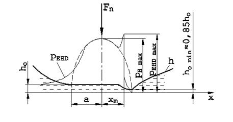
Fig. 2. Pressure
distribution pEHD and the shape of the lubrication gap h in the
elasto-hydrodynamic contact (EHD) between surfaces and the lubricant [1]
The parameter Rq can be
determined from the following formula [5]:
![]() ��������������������������������������������������������������������� (2)
��������������������������������������������������������������������� (2)
Boundary lubrication
occurs when the parameter λ ≤ 1. A mixed friction occurs for the
following range of the oil film thickness: 1 <λ <3. In turn, in the
range of values λ = <3,10>, conditions for liquid lubrication EHD
are generated (a comprehensive description of the theory of the
elasto-hydrodynamic lubrication EHD can be found in [5]), which are
characterized by the occurrence of an oil film layer with a thickness exceeding
the surfaces� irregularities. Above the relative value of the oil film
thickness λ> 10, liquid friction (HD) occurs [2-4].
2.
ASSUMPTIONS FOR CALCULATIONS AIMED AT DETERMINING THE MINIMUM THICKNESS OF
THE LUBRICANT LAYER
In this study, the
method described in the ISO/TR 15144-1: 2014 (E) [6] standard, which is based
on the Dowson and Higginson studies [3], was used to calculate the minimum
thickness of lubricant layer hmin.
In this method, Equation
(2) takes the following form:
![]() �������������������������������� (3)
�������������������������������� (3)
where R� is the radius of
curvature, U is the speed parameter, W is the load parameter, G is the material
parameter and S is the temperature parameter.
In ISO/TR 15144-1: 2014
(E), the calculations of the relative value of the oil film thickness λ
are only carried out for five characteristic points on the engagement section
(Points A, B, C, D and E). For this study, it has been assumed that the values
of the oil film thickness are to be determined for 106 other points of the engagement
section.
In order to determine
the minimum thickness of the lubricant layer, hmin, geometrical parameters of
the teeth of the spur gear stage of a right-angle planetary gearbox (with the
gear ratio i=39; Figure 3), used in mining armoured face conveyors (Table 1
summarizes the geometrical parameters of the teeth), and the load values
corresponding to the power of driving motors (250, 315 and 400 kW; Table 2
shows the values of torque and rotational speed for this stage depending on the
power of the driving motor) were adopted for the calculations. In addition, a
decision was made to perform calculations for mineral oils in the range of
viscosity classes VG68�VG460 (Table 3 summarizes the parameters of these oils)
and for the range of surface roughness Ra=0.15-2 μm.
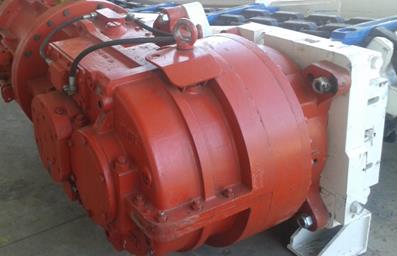
Fig. 3. A view of the
right-angle planetary gearbox used in the drive of mining armoured face
conveyors
Tab. 1
Parameters of the gear
wheels subjected to various technological processes
|
Parameter |
Symbol |
Pinion |
Gear wheel |
|
|
Number of teeth |
z |
23 |
67 |
|
|
Module pitch, mm |
m |
7.5 |
||
|
Pressure angle, � |
α |
20 |
||
|
Teeth width, mm |
b |
120 |
120 |
|
|
Tooth root filled radius |
ρ |
0.380�m |
||
|
Accuracy class |
- |
6 |
||
Tab. 2
Basic geometrical
parameters of gear wheels of the right-angle spur planetary gearbox
|
Driving motor power, kW |
250 |
315 |
400 |
|
Input torque of the gear stage, Nm |
5,760 |
7,255 |
9213 |
|
Input rotational speed of the gear stage, RPM |
414 |
||
Tab. 3
List of parameters
characterizing the examined mineral lubricating oils�
|
Viscosity grade of oil |
Kinematic viscosity at
40�C, mm2/s (cSt) |
Kinematic viscosity at
100�C, mm2/s (cSt) |
Density at 15�C, kg/m3 |
|
VG68 |
68 |
8,7 |
887 |
|
VG100 |
100 |
11,4 |
891 |
|
VG150 |
150 |
15,0 |
887 |
|
VG220 |
210 |
18,5 |
895 |
|
VG320 |
320 |
25,0 |
903 |
|
VG460 |
460 |
30,8 |
904 |
3. CALCULATION RESULTS
When analysing possible solutions for the technical and economic problems mentioned, the calculation results
concerning the relative value of the oil film thickness λ, as a function
of the position of gear wheels of the gearbox on the engagement section, are as
presented in Figure 4.
When analysing the curve
presented in the figure above, it can be concluded that the smallest values of
the λ parameter are observed at a single-tooth engagement point (Point B)
of the engagement section. The lubrication
conditions of the gearbox just at this point of the engagement section were
adopted for the purposes of further analysis. Figure 5 shows plots of the
relative oil film thickness λ, as a function of the power of the driving
motor, and the viscosity grade determined for the roughness Ra=0.4 μm, while
the plots in Figure 6 refer to the roughness Ra=0.8 μm.
Figure 7 presents plots of the relative oil film thickness λ, as a
function of the surface roughness, and the viscosity grade determined for the
driving motor power P=315 kW.
Taking into account the results presented in Figures 5-7, the following
observations can be made:
- The relative thickness of the oil film determined
for the roughness Ra = 0.8 μm, regardless of the load and type of oil,
takes the values lower than 1 (λ <1)
- The relative thickness of the oil film determined
for the roughness Ra=0.4 μm, for the majority of the load and oil values
considered, takes values lower than 1 (λ <1); values λ> 1 are
observed only for the motor power range P=50-150 kW, and for the oil with the
viscosity grade VG460, as well as for the motor power P= 0 kW and for the oil
with the viscosity grade VG320
- The relative thickness of the oil film determined
for the motor power P=315 kW, for the majority of the load and oil values
considered, takes values lower than 1 (λ <1); values λ> 1 are
observed only for the viscosity grades VG150-460 and for the roughness Ra=0.15
μm, as well as for the oil with the viscosity grade VG460 and for the
roughness Ra=0.25 μm
Fig. 4. The plot of the relative oil film thickness
λ as a function of the position on the engagement section for the second
stage of the right-angle spur planetary gearbox
(the results obtained for motor power P=315 kW, viscosity grade VG320 and
roughness Ra=1 μm)
Fig. 5. Plots of the
relative oil film thickness λ at Point B of the engagement section as a
function of the power of the driving motor and the viscosity grade (the results
obtained for
Ra=0.4 μm)
Fig. 6. Plots of the
relative oil film thickness λ at Point B of the engagement section as a
function of the power of the driving motor and the viscosity grade (the results
obtained for
Ra=1 μm)
4. SUMMARY
Around the world,
research is being carried out to improve the durability and reliability of
machine parts [7-22].
As a part of this study,
the lubrication conditions of a typical mining gearbox used in drives of
longwall armoured face conveyors were determined using a modified calculation
method based on the ISO/TR 15144-1:2014 (E) standard. The spur gear stage of a
KPL-25 gearbox with the gear ratio i=39 was subjected to analysis. The values
of the relative oil film thickness λ were determined as a function of the
position on the engagement section. Based on the plot, it has been found that
the smallest values of the parameter λ are at the single-tooth engagement
point (Point B) on the engagement section.
For single-tooth
engagement Point B on the engagement section, the values of the relative oil
film thickness λ were determined as a function of load, oil viscosity
grade and roughness.
The scope of the
analytical work carried out allowed for the following conclusion to be made:
the gearbox under consideration operates unfavourable conditions of boundary
lubrication; only in some cases is it possible to create mixed lubrication
conditions.
Based on the data
presented, it is also possible to formulate a general recommendation to take
into account the operating conditions of gearboxes at the design stage and
select appropriate technological means, which ensure the best-possible
lubrication conditions.
Fig. 7. Plots of the
relative oil film thickness λ at Point B of the engagement section as a
function of the roughness and the viscosity grade (the results obtained for
power P=315 kW)
References
1.
Sko�
Antoni, Jacek Spa�ek, Sylwester Markusik. 2014. Basics of Machine Construction. Vol.
II. Warsaw: WNT. ISBN 978-83-2043-405-7.
2.
Lawrowski
Zbigniew. 1996. Lubrication Technology. Warsaw:
PWN. ISBN 978-830-1074-890.
3.
Dowson
D., G.R. Higginson. 1976. Elastohydrodynamic
Lubrication. Oxford, London: Pergamon Press. ISBN 978-148-318-1899.
4.
Hamrock
B.J., D. Dowson. Ball Bearing Lubrication.
1981. New York, Chichester, Brisbane, Toronto, Singapore: John Wiley &
Sons. ISBN 978-047-1035-534.
5.
Wi�niewski
M. Elastohydrodynamic Lubrication.
2000. Renningen-Malmsheim: Expert Verlag. ISBN 978-3-8169-1745-8.
6.
ISO/TR
15144-1:2014 (E) Calculation of Micropitting Load Capacity Of Cylindrical Spur
And Helical Gears � Part 1: Introduction and Basic Principles.
7.
Bigo�
P., J. Ku�ka, M. Manti�, M. Kopas. 2015. �Comparison of local stress values
obtained by two measuring methods on blast furnace shell�. Metalurgija 54(1): 101-104.
8.
Czech
P. 2013. �Intelligent Approach to Valve Clearance Diagnostic in Cars�. Activities of Transport Telematics. TST 2013. Communications in Computer and Information
Science 395: 384-391. DOI: https://doi.org/10.1007/978-3-642-41647-7_47.
9.
Czech
P., Mikulski J. 2014. �Application of Bayes Classifier and Entropy of Vibration
Signals to Diagnose Damage of Head Gasket in Internal Combustion Engine of a
Car�. Telematics - Support For Transport.
TST 2014. Communications in Computer and Information Science 471: 225-232.
DOI: https://doi.org/10.1007/978-3-662-45317-9_24.
10.
Figlus
T., J. Gnap, T. Skrucany, B. Sarkan, J. Stoklosa. 2016. �The Use of Denoising
and Analysis of the Acoustic Signal Entropy in Diagnosing Engine Valve
Clearance�. Entropy 18(7): 1-11. DOI:
https://doi.org/10.3390/e18070253.
11.
Figlus
T., S. Liscak. 2014. �Assessment of the vibroactivity level of SI engines in
stationary and non-stationary operating conditions�. Journal of Vibroengineering 16(3): 1349-1359.
12.
Grega
R., J. Homisin, M. Puskar, J. KuI�ka, J. Petroci, B. Konecny, B. Krsak. 2015.
�The chances for reduction of vibrations in mechanical. System with
low-emission ships combustion engines�. International
Journal of Maritime Engineering 157(A4): 235-240. DOI:
10.3940/rina.ijme.2015.a4.335.
13.
Harachov� D. 2016
�Deformation of the elastic wheel harmonic gearing and its effect on toothing�.
Grant Journal Vol. 5, No. 1: 89-92,
ISSN: 1805-0638.
14.
Homi�in
J., P. Ka��ay, M. Pu�k�r, R. Grega, J. Kraj��k, M. Urbansk�, M. Moravi�. 2016.
�Continuous tuning of ship propulsion system by means of pneumatic tuner of
torsional oscillation�. International
Journal of Maritime Engineering: Transactions of the Royal Institution of Naval
Architects 158(A3): 231-238. ISSN: 1479-8751. DOI:
10.3940/rina.ijme.2016.a3.378.
15.
Krajn�k
J., J. Homi�in, R. Grega, M. Urbansk�. 2016. �The analysis of the impact of
vibrations on noisiness of the mechanical system�. Diagnostyka 17(3): 21-26.
16.
Kulka
J., E. Faltinov�, M. Kopas, M. Manti�. 2016. �Diagnostics and optimisation of
crane track durability in metallurgical plant�. Diagnostyka 17(3): 41-46.
17.
Medveck�-Be�ov�
S. L. Mikov�, P. Ka��ay. 2015. �Material properties of rubber-cord flexible element
of pneumatic flexible coupling�. Metalurgija
54(1): 194-196.
18.
Puskar
Michal, Michal Fabian, Jaroslava Kadarova, Peter Blist�an, Melichar Kopas.
2017. �Autonomous vehicle with internal combustion drive based on the
homogeneous charge compression ignition technology�. International Journal of Advanced Robotic Systems 14(5). DOI:
10.1177/1729881417736896.
19.
Puskar
Michal, Melichar Kopas, Jaroslava Kadarova. 2017. �Ecological analysis related
to creation of gaseous emissions within transport focused on fulfilment of the
future emission standards�. Transportation
Research Part D: Transport and Environment 57: 413-421. DOI:
10.1016/j.trd.2017.10.007.
20.
Vojtkov�
Jarmila. 2016. �Benefits of application of spur gears with asymmetric profile�.
Pomiary Automatyka Robotyka 2(20):
31-35. DOI: 10.14313/PAR_220/31.
21.
Zeli�
A., N. Zuber, R. �ostakov. 2018. �Experimental determination of lateral forces
caused by bridge crane skewing during travelling�. Eksploatacja i Niezawodnosc � Maintenance and Reliability 20(1):
90-99. DOI: http://dx.doi.org/10.17531/ein.2018.1.12. ISSN: 1507-2711.
22.
Zuber
N., R. Bajri�. �Application of artificial neural networks and principal
component analysis on vibration signals for automated fault classification of
roller element bearings�. Eksploatacja i
Niezawodno�� - Maintenance and Reliability 18(2): 299-306. DOI:
10.17531/ein.2016.2.19. ISSN: 1507-2711.
Received 05.11.2017; accepted in revised form 09.01.2018
![]()
Scientific
Journal of Silesian University of Technology. Series Transport is licensed under
a Creative Commons Attribution 4.0 International License