Article
citation information:
Sekuła, K., Wiącek, D., Motylewski,
J. In-motion
rail scales as a component of the railway bridge diagnostic system. Scientific Journal of Silesian University of
Technology. Series Transport. 2018, 101,
203-213. ISSN: 0209-3324. DOI: https://doi.org/10.20858/sjsutst.2018.101.18.
Krzysztof SEKUŁA[1], Dariusz WIĄCEK[2], Jerzy MOTYLEWSKI[3]
IN-MOTION RAIL
SCALES AS A COMPONENT OF THE RAILWAY BRIDGE DIAGNOSTIC SYSTEM
Summary: The paper presents the Adaptronica company experience in the field of the design, execution and testing of in-motion rail scales. The method of identification of loads applied in these scales is based on the measurement of rail deformations caused by passing trains. The results from experimental and simulation research on computerized railway scales are presented. The load identification algorithm and its practical implementation are shown. The implementation of the system, made on the basis of the device, is described.
Keywords: weigh in motion; railway transport; load identification; load detection procedure; structural health monitoring
1. INTRODUCTION
An important and current technical issue is the assessment of the health condition of railway bridges through the observation and registration of changes taking place in their construction. As a result of ongoing progress in the field of numerical signal analysis and continuous improvement in the functionality of measuring devices, concepts and preliminary implementations of monitoring systems and automatic diagnostics of bridges are being developed.
An exemplary scheme of the monitoring system is shown in Figure 1. According to the cited concept, it consists of two complementary subsystems. One of them is the fault identification system in truss bridges, whose purpose is to register measurement data from sensors placed on the bridge structural elements, on the basis of which it is possible to assess the technical condition of the object on an ongoing basis. The second subsystem is the identification of the load of which the dynamic railway scale fulfils the role. A more detailed explanation of the whole monitoring system of the railway bridge is described in [1]. This paper is focused on the load identification system in railway transport, which was designed in such a way that it can be an independent or be an element of a larger system used for monitoring railway bridges. 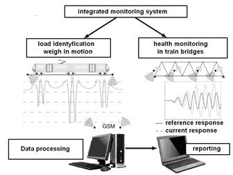
Fig. 1. General scheme of the integrated system
for monitoring loads and damage in railway bridges [1]
2. OVERVIEW OF TRAIN
WEIGHING SYSTEMS IN MOTION
Existing weighing systems can be categorized on
the basis of different criteria, including the operation velocity range of
vehicles while its weight is measured, the sensor type used and the assembling
technology. Here, the authors were focused on the methods of load detector
installation.
In general, two approaches to the determination
of railway traffic load are possible: either using a railway car equipped with
sensors [2] or performing measurements by means of external sensors fixed to
the infrastructure outside the train [4]. The first method is not frequently
applied and it seems to be less effective from a practical point of view.
Hence, the second approach has been more deeply reviewed here. Many kinds of
sensor types and installation technologies have been applied in train WIM
devices. A brief overview of used technologies can be found in the papers
[3,4].
The authors propose to divide the railway
weigh-in-motion (R-WIM) systems on the basis of weight detector installation
technology. As a consequence, the following three main categories can be
introduced:
- Bridge WIM, i.e., systems that utilize the
instrumented bridge measurements for traffic identification [4,5,16]
- Platform WIM, i.e., systems based on force measurement
between the track and an additional solid
foundation [6]
- R-WIM, i.e., systems based on the measurement of
strain development in rails [3]
The device developed by the
authors belongs to the third group and, as a consequence, more information
related to this type of load detector will be mentioned in the next section.
2.1. Overview of rail weigh-in-motion systems
The elastic deformation of the rails
is occurring when the train is passing over it. R-WIM systems operate on the
basis of the strain measurements in rails. In this group of devices, two
potential locations for the strain sensors are commonly used: either mounted on
the rail foot [7] (see Figure 2a) or installed in the neutral axis area of the
rail [8] (see Figure 2b). In the first case, the detector records the
longitudinal deformation of the rail foot, which is mainly related to the
bending effect of the rail. As a consequence, in this case, the sensor is most
commonly installed in the midspan between the sleepers, since it provides the
highest strain values. This is in contrast to the neutral axis sensor location
(in the middle of the rail web), where approximately pure shear stresses are
present. The bending effect is used in the device proposed by the TagMaster
company in Gotcha system [13], contrary to the solution proposed by the Kistler
company [14].
a. b.
b.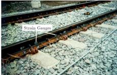
Fig.
2. Two possible locations for the sensor installation:
(a) rail foot, (b) neutral axis of the rail [10]
Various types of the strain sensor are utilized
in R-WIM applications. Probably, the first systems were performed on the basis
of strain gauge measurements [8]; this still seems to be the most frequently
used technique. However, recently, there is growing competition for strain
gauges in the form of optical fibres [9,10] and piezoelectric strain sensors.
In general, it is not possible to state which measurement strain sensor
technique is most appropriate for R-WIM. Researchers [1,15] have proven that a
similar quality of measurements can be obtained by different measurement
techniques.
The important advantage of R-WIM systems is the
wide velocity range of travelling trains, in which the identification of their
weights is possible. Researchers have successfully applied axle load
measurements for trains travelling at a velocity of 300 km/h [9]. However, in order to overcome the
velocity limitations, the accuracy of results must be sacrificed. In [7], it
was shown that the load identification error increases together with the
velocity identification.
As the rail is in direct contact with the train
wheels, the strain measurements are able to provide estimations of relatively
many parameters, which is a great benefit of R-WIM systems. Quantities, such as
individual wheel and axle loads, the gross weight of each railway car, the
number of railway cars, total train weight, velocity, direction of movement and
even the state of the wheel, e.g., polygonization, can be identified. The
sensors, which are commonly installed in bough rails, allow for the estimation
of the unbalanced axle load.
The important advantage of R-WIM is its
relatively low cost. Very often, no additional maintenance operations,
especially preparing the track (e.g., replacement of the sleepers or the
installation of a solid foundation) before sensors are attached, is necessary.
Another benefit is the possibility of creating an installation, even during
traffic, provided that some safety conditions are respected.
It should be mentioned that the tracks are an element of the measurements system. As a consequence, the condition of tracks has an influence on the identification precision. Moreover, since the tracks’ condition is not always the same, the axle load’s rail strain relation is not known before sensor installation. This forces the calibration of the measurement system. The most commonly used method is to apply the train with a known weight.
Thanks to the advantages of R-WIM technologies,
significant developments in this field have been recently observed. Several
scientific or commercially available techniques, using various sensors or
methods of installation, can be found. Generally, R-WIM systems can be
distinguished according to two main categories, i.e., non-intrusive and
intrusive, on the basis of the sensor assembling technique. In the first case,
the sensor installation does not have any effect on the rails, as the sensor is
usually glued onto them. In the intrusive system, sensor installation requires
a rail intrusive operation, with the drilling of the rails being the most
commonly used. The other group comprises portable systems where sensor
installation is not time-consuming and the return of the rails and the whole
track to the previous (i.e., pre-installation) state is easy. One example of
such devices was patented by the Adaptronica company. Contrary to what is mentioned
above, generally, emplaced type detectors, once they are anchored, are usually
not removed and tend to be dedicated to the continuous detection of traffic
information. Typically, portable systems are also non-intrusive technology
because, after they are remove, there is no visible effect on the track.
3. THE CONCEPT FOR THE DEVELOPED
RAIL WEIGH-IN-MOTION SYSTEM
The load identification
is performed in an indirect way using the rail deformation recorded during the
passage of the train. Generally, two locations for the sensor’s placement
are possible. As mentioned earlier, the strain sensors could be located either
on the rail foot or to the rail web. The authors have chosen the former
because, in this case, the sensors are less visible and partially sheltered
from the rain. The strains are collected by the sensors (piezoelectric or
strain gauge were used) mounted to the bottom part of the rail foot in the
sleepers. The general concept of the aforementioned method is presented
in Figure 3.
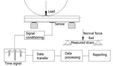
Fig.
3. General concept for the R-WIM system
4. THE LOAD
IDENTIFICATION ALGORITHM
Implementing the direct measurement of loads in rail transport is difficult in practice; therefore, indirect methods are used [1]. The load identification problem belongs to the class of inverse problems presented in [11]. Generally, solving this the problem involves find a relation between the output (registered measurement signals) and input (axle load) in a given system. In order to perform this task, it would be reasonable to register the relationship, in an experimental manner, between these sizes during the work of the considered systems. This is usually difficult to carry out because, in the case of environmental enforcement (i.e., vehicle traffic), usually, only an exit (answer construction at the given load) can be measured reliably.
In the proposed R-WIM system, the pattern
recognition scheme has been adopted as the method to solve the inverse problem.
In the method, a YDB database, containing a mapped response design for
various load variants, is used. This database can be presented as a set of
values of the function described by the following relationship:
![]() .
(1)
.
(1)
Formula (1) contains significant factors affecting the measurement: Qstat - measured static load value, T - temperature, v - moving speed composition, an - number of axles in the wagon, rsc- rail support condition etc.Preparing a database involves carrying out a type of sensitivity analysis. This can be done during field research, which, for the proposed devices, was based on the crossings of railway cars with a known load distribution through the measuring zone. Another way is to perform simulation tests using a verified numerical model.
Generally, identification according to the proposed method consists of finding a vertical load, which is the same as the contact force occurring between the wheel and the Qid rail. This can be performed by minimizing the difference between the currently registered YM and the measurement signal value similar value, as memorized in the database:
![]() .
(2)
.
(2)
The registration of measurement signals can be influenced by many factors. In order to simplify the identification procedure (reducing the number of variables), it is possible to use an internal calibration procedure for vehicles with a specific mass. Electric locomotives, e.g., ET-22, are ideal for this purpose as their mass is not influenced by the amount of fuel or the number of passengers. As it has been shown that the composition of a locomotive of this type is possible, the preliminary determination of the R relation between the value of the YML signal is generated by the locomotive and the known static load of QML, according to the dependence:
![]() .
(3)
.
(3)
On the basis of the currently
measured strain Yact and
the relationship in (3), it is possible to determine the mass of other wagons
using the formula in (4):
![]() ,
(4)
,
(4)
without the need to analyse the influence, for example, of temperature T and speed v, because this information already contains the parameter R, specified for the given composition
under specific travel conditions. However, the formula does not consider the
quantities related to some non-linear effects. In order to include the load
distribution O(an)
or influence the non-linear nli axle load
strain relation, the formula in (5) should be applied.
![]() (5)
(5)
5. COMPUTER MODELLING
OF RAIL-SLEPER-GROUND INTERACTION
The objective behind the preparation of a
numerical model of rail-sleeper-ground interaction was to identify the rail and
train configuration parameters from the load identification point of view. The
factors influencing the dynamic response of the rail, e.g., the number of axles
per bogie, were taken into consideration. The main objective of the analysis is
to obtain the model calibration factors in order to ensure the precision of the
load identification algorithm.
The railway track was modelled using the ADINA
finite element package. It was assumed that the
load acting on the track is distributed symmetrically; in order to reduce the
computing effort, only one rail on the track has been modelled. A scheme of the
model is illustrated in Figure 4.
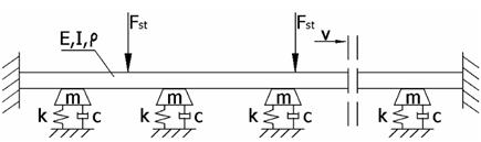
Fig. 4. Model of rail-sleeper-ground
interaction [1]
The rail was modelled as a beam according to the Rayleigh-Timoshenko theory. Beam parameters, such as density ρ, Young modulus E and moment inertia I, were the same as for a real S60 rail. The Kelvin-Voigt model (spring and damper in parallel) was employed in order to model rail-sleeper-ground interaction. The stiffness k and damping parameters c of the model were applied on the basis of the experimental data. The load was modelled with the aid of a system of vertically concentrated forces Fst and moving in the horizontal direction with a constant speed v. A more detailed explanation of the presented model can be found in [1].
5.1 Verification of the numerical
model
The numerical results obtained from the
computer model were validated on the basis of the experimental measurements. A
comparison of the results for the passage of an ET-22 locomotive is shown in
Figure 5. The locomotive weighs 120 tons and is supported by two three-axle
bogies; this configuration is visible in the graph.
Figure 5a represents the vertical displacement
of the rail, with the experimental data acquired by using laser displacement sensors. Generally, it should be
stated that the track is direct, that the measurement zone was in a bad
technical condition and that the observed displacements of foundations were of
a size greater than in the case of literature data [12]. The displacement sensor results were only
used for model validation, while they are not applied in developed R-WIM
systems.
Figure 5b presents the time history of strain
in the bottom part of the rail. This quantity is directly used in the R-WIM
system. The experimental data were measured by strain gauges in the half-bridge
mode located in the midspan between the sleepers. Despite the fact that the
load is equally distributed to the six axles, the experimental and numerical
data show that the amplitude of strain corresponding to the middle axle of
bogie is 25% smaller than for the outside ones. This is the result of
deflecting the line of the rail.
a)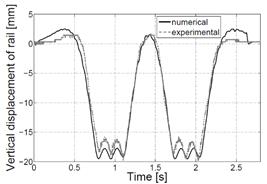 b)
b)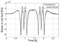
Fig.
5. Comparison of numerical and experimental results: a) vertical displacements
of the rail, b) stresses in the rail foot
5.2 Analysis of the load
distribution effects
Since railway cars may have a different number
of axles per bogie, the analysis of load distribution effects on rail strain is
considered in this section. For this purpose, numerical simulations were
performed, in which the load exerted by the wagon on the rails is spread across
a different number of concentrated forces. The arrangement of modelling forces
on the load was selected in such a way that their distances corresponded to the
spacing axes occurring in typical wagons and locomotives. Five cases of load
distribution were analysed. The total load value was the same in all
simulations. The obtained numerical results are shown in Figure 6. The graph
presents a relative change in rail strain as a function of the axle number with
the load distribution for the three-axle bogie serving as a reference.
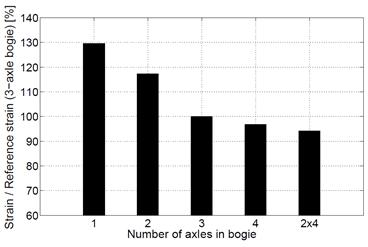
Fig. 6. The dependence of the number of axles in the bogie on the maximum relative deformation of the rail Rail deformation is based on the quantity used
for the load identification in the R-WIM system. The simulation results
emphasize the significance of the number of axles in the bogie rail
deformation. As a consequence, this parameter should be considered in the load
identification algorithm. This factor is especially important when using the
online calibration method (with the locomotive serving as a reference). The
need for such a correction derives from the fact that locomotives usually run
on three-axle bogies, while freight cars run on two-axle ones. Otherwise, the
cars with a smaller number of axles might be identified as heavier than in
reality. In the case of two-axle bogie wagons, the weight would be
overestimated by 18% (see Figure 6).
6. EXPERIMENTAL VERIFICATION OF THE
DEVELOPED RAIL WEIGH-IN-MOTION SYSTEM
The R-WIM system was installed in
Nieporęt, near Warsaw, in the area of the bridge over the
Żerański Canal. The device was equipped with four piezoelectric
strain sensors located in the rail foot, according to the concept mentioned in
Section 3. The two sensors were installed in bough rails at a distance of
The system was verified on the basis of the
reference trains, which were weighed beforehand on the low-speed weighing
station near Warsaw. The reference scale was produced by Schenk typ. DGW-B
8+5+5, which is characterized by the third class of accuracy; the scale
interval was 50 kg.
Figure 7 illustrates the time signal collected
by the piezosensor during the passage of a freight train. Each axle of the
bogies running over the WIM measuring point can be recognized. The first part
of the signal (approximately 15 s) corresponds to an ET-22 locomotive with two
three-axle bogies. The remainder of the acquired signal is the result of the
passage of 29 wagons, most of which were supported by two two-axle bogies.
However, four of the last six wagons were supported with two three-axle bogies.
As a consequence, three wagons were characterized by an analogical axle
configuration as in the case of the locomotive. The presented train was weighed
by use of the aforementioned reference scale. The measured weight of each of
the wagons is depicted in the graph. The weight of the locomotive was 120
tonnes, while the wagons weighed 23.3-33.6 tonnes.
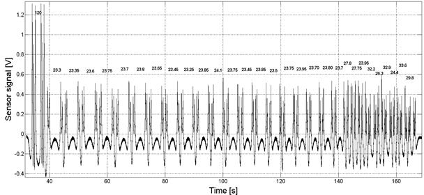
Fig.
7. Time signal from the piezosensor as a response to the passage of a freight
train
In the first stage, the wagons’ weight identification by using the R-WIM device was applied on the basis of the formula in (4). The mass of the locomotive was used for measurement system calibration. The signal amplitudes that related to each of the axles were the quantities used in the load identification methodology. The system identification precision is shown in Figure 8, which shows the percentage difference between the R-WIM values and the reference scale value. A significant difference in the case of the wagon supported by a two-axle bogie was noticed, while good agreement was observed in the case of the three-axle bogie. The two-axle wagon weight was overestimated by about 18±4%. These results do not contradict the computer simulation, as seen in Figure 6. 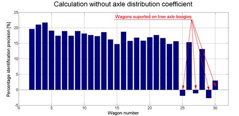
Fig.
8. Wagons’ weight identification precision, based on the formula in (4)
In order to improve the
identification precision, the procedure based on the formula in (5) was
applied. Here, the load distribution was considered to result in a significant
improvement in the identification precision, with the inaccuracy being less
than 5% in that case.
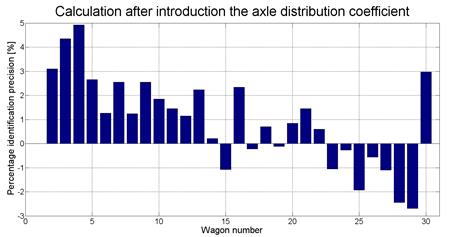
Fig.
9. Wagons’ weight identification precision based on the formula in (5)
6. CONCLUSION
This paper presented an experimental and numerical analysis of a WIM system dedicated to railway transport. This device can complement the monitoring system conditions of truss railway bridges. The developed device is the R-WIM system and, as a consequence, a literature review of the relevant group scales was introduced.
A load identification method is proposed here, based on the measurement
of railroad deformation caused by passing trains. Piezoelectric
sensors were used to measure the deformation and, for comparative purposes,
strain gauges were applied. The acquired data were used for model of
rail-sleeper-ground interaction validation. The model was used in the
development of a load identification algorithm. The algorithm, which is based
on online calibration, makes the measurements insensitive towards environmental
conditions. The numerical and experimental results have proven that the load distribution effect must be considered in the
load identification algorithm.
Studies have shown that piezoelectric sensor deformation can be used to identify loads and is a good alternative to other measuring techniques. References
1.
Holnicki-Szulc
Jan, Andrzej Świercz. 2014. Monitorowanie
obciążeń i stanu technicznego konstrukcji mostowych. [In Polish: Monitoring the Loads and Technical Conditions of Bridge Structures.]
IPPT Reports on Fundamental Technological Research. ISBN 978-83-89687-88-3.
2.
Uhl
Tadeusz. 2007. “The Inverse Identification Problem and Its Technical Application”.
Archive Applied Mechanics 77:
325-337. DOI: 10.1007/s00419-006-0086-9.
3.
Meli E., L. Pugi. 2013. “Preliminary Development, Simulation and
Validation of a Weigh in Motion System for Railway
Vehicles”. Meccanica 48(10): 2541-2565. DOI:
10.1007/s11012-013-9769-9.
4.
Axel
Liljencrantz. 2007. Monitoring Railway
Traffic Loads Using Bridge Weight-in-motion. PhD thesis. Stockholm, Sweden:
Division of Structural Design and Bridges, Royal Institute of Technology.
5.
Žnidarič
Aleš, Jan Kalin, Maja Kreslin, Peter Favai, Przemysław Kolakowski.
2016. “Railway Bridge Weigh-in-motion
System”. Transportation Research
Procedia 14: 4010-4019. Available at:
https://doi.org/10.1016/j.trpro.2016.05.498.
6.
Denis M. Senyanskiy. 2003. “Problem
of Increasing the Accuracy of Railway Carriages Weighing in
Motion”. XVII IMEKO World Congress. Available
at: http://www.imeko.org/publications/wc-2003/PWC-2003-TC3-027.pdf.
7.
Ignesti
Mirko, Alice Innocenti, Enrico Meli, Luca Pugi, Andrea Rind. 2013. “Development and Validation of
Innovative Weighing in Motion Systems”. Chemical Engineering Transactions 33. DOI: 10.3303/CET1333128.
8.
James
G. 2003. Analysis of Traffic Load Effects
on Railway Bridges. PhD thesis. Stockholm, Sweden: Structural Engineering
Division Royal Institute of Technology.
9.
Massimo
Leonardo Filograno, Pedro Corredera Guillén, Alberto
Rodríguez-Barrios, Sonia Martín-López, Miguel
Rodríguez-Plaza, Álvaro Andrés-Alguacil, Miguel
González-Herráez. 2012.
“Real Time Monitoring of Railway Traffic Using Fiber Bragg Grating
Sensors”. IEEE Sensors
Journal 12(1): 85-92.
10.
Lai C.C., Jacob C.P. Kam, David C.C. Leung, Tony
K.Y. Lee, Aiken Y.M. Tam, S.L. Ho, H.Y. Tam, Michael S.Y. Liu. 2012. “Development of a Fiber-optic Sensing System
for Train Vibration and Train Weight Measurements in Hong Kong”. Journal of Sensors. Article ID 365165. DOI: 10.1155/2012/365165.
11.
Inoue
H., J.J. Harrigan, S.R. Reid. 2001. “Review of Inverse Analysis for Indirect
Measurement of Impact Force”. Applied
Mechanics Reviews 54(6): 503-524. DOI:10.1115/1.1420194.
12.
Nielsen
J., J. Oscarsson. 2004. “Simulation of Dynamic Train-track Interaction with State-dependent Track
Properties”. Journal of Sound and
Vibration 275: 515-532. Available at:
https://doi.org/10.1016/j.jsv.2003.06.033.
13.
TagMaster.
2016. Wheel Flat Detection and Axle Load
Measurement. Technical Report. Available at:
https://tagmasterna.com/wp-content/uploads/2016/05/Gotcha.pdf.
14.
Cornu
D. 2008. Weight-in-motion Unique Quartz
Sensor Technology: Now Also for Railways. Technical Report. Winterthur:
Kistler. Available at:
http://www.bleif.com.ar/assets/img/productos/files/Trasductores-de-Presion/Weigh-In-Motion-Railways.pdf.
15.
Ostasevicius
V., I. Milasauskaite, R. Dauksevicius, V. Baltrušaitis, V.
Grigaliūnas, I. Prosyčevas. 2010. “Experimental
characterization of material structure of piezoelectric PVDF polimer”. Mechanika 6: 78-82.
16.
Moravcik
M., M. Moravcik. 2017. “Resonance vibration of railway bridges subjected
to passing vehicles”. Komunikacie
3: 96-102.
Received 04.08.2018; accepted in revised form 01.11.2018
![]()
Scientific
Journal of Silesian University of Technology. Series Transport is licensed
under a Creative Commons Attribution 4.0 International License