Article
citation information:
Sakhno, V., Poliakov, V.,
Murovanyi, I., Selezniov, V., Vovk, Y. Analysis of transverse stability
parameters of hybrid buses with active trailers. Scientific Journal of Silesian University of Technology. Series
Transport. 2018, 101, 185-201.
ISSN: 0209-3324. DOI: https://doi.org/10.20858/sjsutst.2018.101.17.
Volodymyr SAKHNO[1],
Victor POLIAKOV[2],
Igor MUROVANYI[3],
Vadim SELEZNIOV[4],
Yuriy VOVK[5]
ANALYSIS OF
TRANSVERSE STABILITY PARAMETERS OF HYBRID BUSES WITH ACTIVE TRAILERS
Summary. The objective of the article is to
determine the transverse stability indexes of hinge-connected buses (HCBs) by
applying the computation-analytical method. The transverse stability parameters
of hybrid buses with active trailers are analysed. Based on these parameters
(the angles of the roll and redistribution of loads on the sides), the
analytical dependences are developed. The dependences describe the movement of
the parts of HCBs in the vertical plane. Considering the action of longitudinal
and transverse forces, the roll angles of the bus and the trailer were
determined. The limiting angle of the side roll of the bus rollover was found
to be gамах = 27.560gмах, and the trailer rollover to be gамах = 30.210. The obtained transverse stability indexes of HCBs with a hybrid power
plant testify to the compliance with the standard DSTU UN/ECE R 111-00.
Keywords: bus; hybrid auto-train; transverse stability;
stiffness; suspension; roll
1. INTRODUCTION
The
dynamic properties of motion, stability and vehicle handling, to a large
extent, ensure the safety of traffic. At present, the problem of determining
the conditions of dynamic system stability is sufficiently studied. However,
the challenge is to define the nature of the system’s behaviour in the state
of instability and identify the causes of its occurrence.
The
main parameters of any vehicle (indicators of its ability to perform its
functions) are the overall dimensions, mass parameters, speed and dynamic
characteristics of transportation, etc. Passenger capacity and turnover,
acceleration dynamics, stability, handling and especially manoeuvrability are
highly important factors in the operation of city buses. In most countries,
according to UN/ECE Regulation No. 36, the overall length of single buses is
limited to
The
normalized indexes of manoeuvrability of large-class buses (HCBs) can be
developed due to appropriate layout schemes and the use of directive
(self-installing) wheels in the trailer section (trailer), which can be driven
by an electric motor located in the coupling section. In [2], the required
power of the electric motor, which is installed in the trailer section of the
bus, is determined under the conditions of starting from the following: rest,
rectilinear motion and circular motion. However, the retrofitting of the bus
with an additional engine located in the trailer section requires verification
of its stability in order to ensure a guaranteed level of its external passive
safety.
The
creation of requirements for guaranteeing the required level of the external
passive safety of passenger vehicles in conditions of overturning began in 1973
after a terrible bus rollover accident. This led Hungary to raise this issue
for the first time at the ECE Summit in Geneva [3]. It took 12 years to create
the relevant regulatory requirements until the first revision of UN/ECE
Regulation R66 appeared. The main problem was to create an adequate research
method for the real rollover process. Based on this method, the strong spatial
structure of the body can be easily distinguished from the weak one [4]. The
reduction in the strength of the body spatial structure degrades passenger
safety indexes [5].
A
forklift truck or a truck crane acts as the test equipment for lifting the
platform. It must ensure the simultaneous raising of axes with the difference
in the platform inclination angles measured below these axes being less than
1°. In the case of separate platforms (Figure 1a, c-d), the synchronization
of the lift is provided by two automobile cranes.
An
additional requirement for the test equipment is the simultaneity of lifting
all the model axes without rocking and dynamic impact until the model rolls
over, with an angular speed up to 5°/s (0.087 rad/s). According to the
results obtained in various testing laboratories, this index varies in the
range from 0.64 to 5°/s.
The
indexes of stability assessment are the critical values of motion parameters
characterizing the dynamic stability and the positions characterizing the
static stability of the car and the auto-train [3]. Recommended values of the
vehicles’ stability indexes and the methods of their determination are
given in UN/ECE Regulation No. 107, MS ISO 4188-82, GOST 3163-76, GOST R
52302-2004, OST 37.001.471-88, OST 37.001.487-89, DSTU 3310 -96.
|
a) |
b) |
c) |
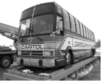
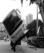
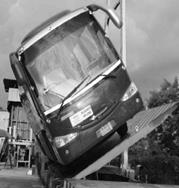
Fig. 1. General view of the test
platform with the installed model of a bus:
a) Prevost Lemirage Motor Coach [8], b) Scania-Higer [9], c) IRIZAR PB Tour Bus
[10]
Motor
cars and small trucks can be easily tested by a turnover testing unit, while
testing heavy trucks and especially auto-trains, as well as HCBs, incurs great
difficulties, in particular, in the case of hinge-connected hybrid buses of a
specifically large class with an active trailer. Thus, the purpose of the work
is to determine the indexes of transverse stability of HCBs by the
computation-analytical method [25].
2. MATERIALS AND METHODS
The application of the computation-analytical method for determining the parameters of the HCB’s motion in the horizontal and vertical planes greatly simplifies the definition of these indexes [5].
Numerous studies have proven that there are mutual non-linear relationships between the variables characterizing auto-trains’ movement in the horizontal and vertical planes; the relations in different cases of motion are different. The practice of studying the motion stability of both single vehicles and auto-trains in different regimes is extensive [6,7,24,26,27].
In this paper, the HCB’s movement in the vertical plane along the angles of pitch (pitch, trim) and the roll are assumed to affect the lateral movement, mainly by changing the vertical loads on the wheels. The vertical reactions of the support surface are changed as well. In accordance with this concept, the movements were divided into lateral and longitudinal-transverse ones. Nowadays, the lateral movement is sufficiently studied [5-7], but the longitudinal-transverse motion should be investigated further. The spring and unsprung parts of the HCB’s real construction are assumed to be connected with the help of elastic and damping elements, while the unsprung masses and the road are assumed to be connected with the help of tyres that possess both elastic and damping properties. At low velocities, the vertical displacements of spring and unsprung masses are carried out synchronously. In this case, there should be a static compression of the springs and tyres at low resistance of the shock absorbers [8]. Similarly, the spring masses are assumed to carry oscillations on the springs with some stiffness.
According to this approach, the forces acting on the support-coupling device do not affect the redistribution of loads on the sides of the HCB. The axis of the roll lies in the vertical plane of symmetry. Therefore, a complex system such as an HCB can be considered as two systems that independently roll: a bus and a trailer section (trailer). Thus, the appearance and the analysis of the equations describing the roll are simplified.
Let us first
formulate the equation of HCB parts’ motion in the longitudinal and
transverse planes [9]. For this purpose, the following notations are
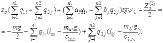
introduced: ![]() - unsprung masses
of the іth front and
jth rear suspensions; с1i, с2j,
с1іш, с2jш -
respectively, radial stiffness of suspensions and tyres;
- unsprung masses
of the іth front and
jth rear suspensions; с1i, с2j,
с1іш, с2jш -
respectively, radial stiffness of suspensions and tyres; ![]() - static
deflections of suspensions;
- static
deflections of suspensions; ![]()
![]() - vertical
deformations of tyres;
- vertical
deformations of tyres; ![]()
![]() - vertical
reactions of the ith front
and jth rear supports on
the bus body; z0.
- vertical
reactions of the ith front
and jth rear supports on
the bus body; z0. ![]() - the height of
the location of corresponding points C,
Сai and Сbj
(Figure 1) above the support surface in undeformed suspensions and tyres,
j -
the angle of assembly of the train. In a state of static equilibrium, the
applicates of these points are defined as in [9]; see Figure 2.
- the height of
the location of corresponding points C,
Сai and Сbj
(Figure 1) above the support surface in undeformed suspensions and tyres,
j -
the angle of assembly of the train. In a state of static equilibrium, the
applicates of these points are defined as in [9]; see Figure 2.
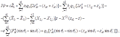
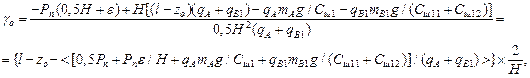
![]()
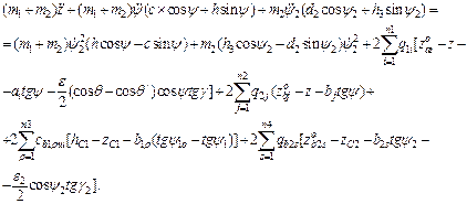
![]() (1)
(1)
Based the condition of forces equilibrium (Figure 1), we find:
![]()
![]() (2)
(2)
where ![]() =
=![]() (
(![]() ,
, ![]() =
=![]()
![]() ,
, ![]() ,
, ![]() (3)
(3)
Since a piecewise linear approximation is assumed in the recorded functions, then:
![]() ,
, ![]() ,
, ![]() ,
,
![]() (4)
(4)
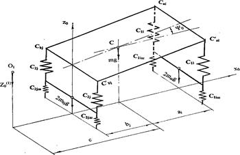
Fig. 2. On determining the state of the bus’ static equilibrium
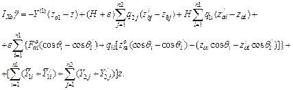
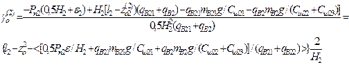
Then, based on (4) and (2), the expressions of the tyres’ vertical deformations are deduced:
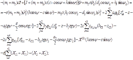
![]()
 (5)
(5)
Based on (1) and (5), the formulae are developed thus:
 ;
;  (6)
(6)
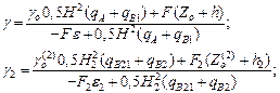
Substituting (5) with (4):
![]()
 ,
(7)
,
(7)
where ![]() ;
;  (8)
(8)
The stiffness of two series-connected elastic elements, a suspension and tyres is given (Figure 2):
The equilibrium equation of the traction car body [9] (Figure 3) is:
![]()
In an expanded form, it is presented as:

 ,
(9)
,
(9)
and
![]() ,
,
![]()
Substituting (7) with (9), the following formulae [9] are deduced:
 (10)
(10)
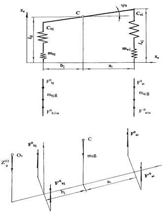
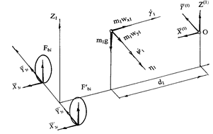
Fig. 3. Scheme of forces acting on the bus in the state of static equilibrium
The values Zo, yo and ![]() are unknown in
(10).
are unknown in
(10).
Let us derive the
dynamic equations of a tractor. By analogy with (2), vertical reactions of the
supporting surface (Figure 3) are found:
![]() (11)
(11)
where:
![]() (12)
(12)
When the system deviates from the state of the static equilibrium, the restoring forces of the suspensions’ elastic elements are equal to:
 (13)
(13)
After the exclusion
of the vertical deformations of tyres ![]() (13) on the basis
of (12), as well as the values
(13) on the basis
of (12), as well as the values ![]() on the basis of
(1), we obtain:
on the basis of
(1), we obtain:
 (14)
(14)
Factoring in the known zai, zbj or Fai, Fbj, the vertical reactions on the wheels of the left side are written thus:
![]() (15)
(15)
where:
![]()
![]() (16)
(16)
By analogy with (15), the vertical reactions on the wheels of the right side are written as:
![]() (17)
(17)
Vertical reactions of the road cloth are considered in three equations of the bus body (Figure 3):
![]() ;
;
![]() ;
;
![]() ,
,
where: І, ІХо - moments of the tractor inertia about the transverse and longitudinal axes passing through the tractor’s centre of mass (point C).
The following notations are entered:
![]() ;
;
![]() ;
;
![]() ;
;
![]() .
.
Based on Figure 4, the following dynamic equations, which describe the vertical displacement of the tractor’s centre of mass, rocking and roll, are developed [9]:
![]() ;
;
 (18)
(18)
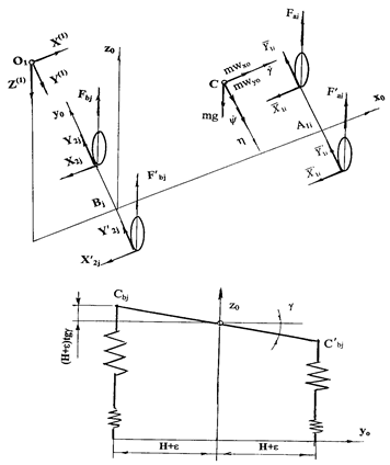
Fig. 4. Scheme of forces acting on the bus in the state of dynamic equilibrium
Taking into account expressions (6) and (7), the expressions for determining the reactions of suspensions of the bus body are presented [9]:
![]()
 (19)
(19)
In the expression that determines the vertical reaction in the traction coupling unit, the static and dynamic components are defined:
![]() (20)
(20)
Based on the static equations (6) and expressions (19) and (20), the dynamic equations (18) can be represented as [9,20]:
![]() ;
;
 (21)
(21)
By analogy with (1)
and taking into account Figure 2, for the applicates of the point ![]() , the following formulae are developed:
, the following formulae are developed:
![]() ,
,
![]() ,
(22)
,
(22)
![]() ,
,
![]() .
.
According to (22):
![]() ;
;
![]() ;
;
![]() ;
;
![]() .
(23)
.
(23)
In accordance with the considered method and Figure 5, the equation of the trailer body motion is written as:
![]() ;
;
![]()
![]() (24)
(24)
where:
![]()
![]()
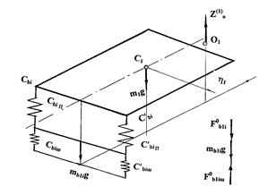
а) b)
Fig. 5. Scheme of forces acting on the trailer in the state of the static (a) and dynamic equilibrium (b)
Equations (21) and
(24) describe the movement of an auto-train in a vertical plane (longitudinal
and transverse) and possess six unknowns: the generalizing coordinates z, y, γ, y2, γ2 and
the dynamic component ![]() of the vertical
reaction in the traction coupling unit. After the exclusion of the latter, an
equation for determining the generalizing coordinates of the auto-train is
deduced. In this case, based on generalizing coordinates, the expressions for zC1, zC2, zo1,
zo2 (Figure 5) are written
of the vertical
reaction in the traction coupling unit. After the exclusion of the latter, an
equation for determining the generalizing coordinates of the auto-train is
deduced. In this case, based on generalizing coordinates, the expressions for zC1, zC2, zo1,
zo2 (Figure 5) are written
![]() ;
;
![]() ;
;
![]() ;
; ![]() ;
(25)
;
(25)
![]() .
.
The value ![]() is derived from
the first equation (24). Considering (25):
is derived from
the first equation (24). Considering (25):
![]() (26)
(26)
The final motion equations of unsprung masses of an auto-train are written as:
- by variable z
- by variable y
- by variable γ

- by variable y2

- by variable γ2
![]() (27)
(27)
The equations (27) describing the motion of the HCB parts in the vertical plane (longitudinal and transverse) are applied in order to find the indexes of the HCB’s transverse stability. In the case of steady motion, the problem is reduced to the analysis of finite equations (the values of the roll angles and the redistribution of loads along the sides are constant). For this purpose, the equation of dynamic equilibrium relative to the points К, К2, К4 is developed; see Figure 6.
The formulae are developed [9]:

Fig. 6. On determining the forces acting on the bus (trailer) in a steady motion
In the expanded form:
 (28)
(28)

If we assume that tggo≈go, tgg2≈g2, H1≈H, then the other equations of a system (17) and (19) can be applied to determine the static values of the roll angles of the train’s parts:
 (29)
(29)
In order to define the dynamic values of the roll angles g, g2, the difference between the corresponding equations (29) and the last system equations (17) should be considered. Then,


Thus:
 (30)
(30)
The dynamic
components of the vertical reactions in the supports, which are defined by the
roll angles g and
gо, g2 and ![]() (loading and
unloading), are determined:
(loading and
unloading), are determined:
- for the left side
DG1=q(g-go)H/2;
DG11=q11(g-go)H1/2; DG2=q2(g2-![]() )H2/2;
)H2/2;
- for the right side
DG11=q1(g-go)H/2;
DG11i=q111(g-go)H1/2; DG12=q12(g2-![]() )H2/2.
)H2/2.
Consequently, the dynamic loads, with consideration of the side redistribution, can be written as:
![]()
![]()
![]()
![]()
![]()
![]() (31)
(31)
Equations (31) are the basis for calculating the values of loading and unloading of the wheels of the bus and the trailer.
The determination of the stability indexes of buses, including the articulated ones, is based on some assumptions: the bus is fully loaded; the mobility of passengers is absent; and the entire unsprung mass acts as a solid body [8].
Output data for
calculating the stability of an articulated bus (Figure 7) are accepted: the
total weight of the auto-train - 25,600 kg; the load on the support-coupling
device of the tractor - 1,990 kg; the total stiffness of the suspension of the
bus front wheels - 640 kN/m, rear wheels - 950 kN/m, trailer wheels - 840 kN/m,
tyre stiffness - 1,250 kN/m; geometric parameters of the auto-train: length -
17,500 mm, width - 2,460 mm, height - 3,585 mm; geometric parameters of the
bus: length - 10,000 mm, width - 2,460 mm, height - 3,585 mm; geometric
parameters of the connected part: length - 7,500 mm, width - 2,460 mm; the
wheel track of the tractor - 1,850 mm, the trailer - 1,850 mm; spring wheels of
a tractor: front wheels -
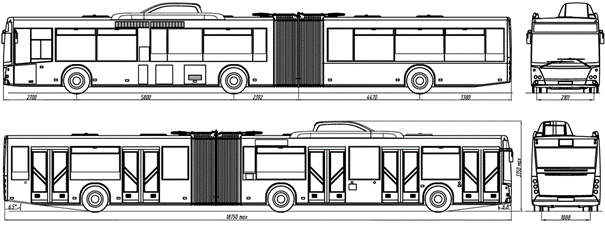
Fig. 7. HCB
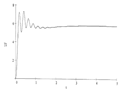
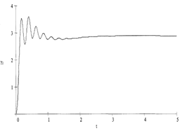
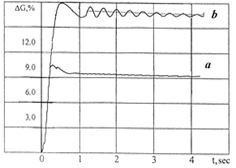
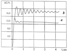
In Figure 8, the results from calculating the roll of the bus body and the trailer during the circle motion are shown. In Figure 9, the values of loading and unloading of the bus wheels while performing the same manoeuvre are presented.
Based on the
above-mentioned dependences, during the circle motion, the HCB’s body
roll and the side loading exceed the indexes of the trailer coupling part. This
is explained by the lower position of the trailer’s centre of mass (hg =
The limiting angle of the lateral roll of rollover gмах characterizes the HCB’s stability when moving along a slope. According to the calculations, this angle is:
- for the bus gамах = 27.560.
- for the trailer gамах = 30.210.
a) b)
Fig. 8. Change in the roll angle of the bus (a) and trailer (b) during the circle motion of the auto-train: R=25 m; v=10 m/s
These angles considerably exceed the possible slopes on highways, that is, the transverse stability of the HCB is greatly ensured, especially for the coupling section, due to the low position of the centre of mass.
a) b)
Fig. 9. Loading the wheels of the bus outer side during the circle motion of the auto-train, while factoring in the roll (a) and the effects of longitudinal and lateral reactions (b): R=25 m; v=10 m/s
4. CONCLUSIONS
In order to ensure safe traffic conditions, which are regulated by international and national rules and standards, the dynamic parameters, in particular, the stability and handling of the vehicles, are studied.
The parameters of the transverse stability of hybrid buses with active trailers are analysed in accordance with the objective of the study. In this paper, the movement of the parts of HCBs in the vertical plane along the angles of rocking (pitch, trim) and the roll are assumed to affect the lateral movement mainly by changing the vertical loads on the wheels. The vertical reactions of the bearing surface are changed as well. The limiting angle of the side roll of the bus rollover is found to be gамах = 27.56°gмах, and the trailer rollover to be gамах = 30.21°. Therefore, the transverse stability of HCBs with a hybrid power plant is ensured, since, according to the standard DSTU UN/ECE R 111-00, this angle should not exceed 25°.
In
addition to technical factors, when talking about safety, it is important to
remember about aspects related to bus passengers and their behavior [21-23].
References
1.
ДСТУ UN/ECE R 36-03:2002.
2002. Єдині
технічні
приписи щодо
офіційного
затвердження
пасажирських
транспортних
засобів
великої
місткості
стосовно
загальної
конструкції
(Правила ЄЕК
ООН №36-03: 1993, IDT). [In Ukrainian: GOST UN/ECE R 36-03:2002. 2002. Uniform Technical Prescriptions
Concerning the Approval of Passenger Vehicles of Large Capacity in Relation to
the Overall Design (UN/ECE Regulations №36-03: 1993, IDT).] Kiev: State
Committee of Ukraine for Technical Regulation and Consumer Policy.
2.
ДСТУ UN/ECE R 111-00: 2002.
2002. Єдині
технічні
приписи щодо
офіційного
затвердження
автоцистерн
категорій N і O
стосовно їх
стійкості
проти
перекидання.
[In Ukrainian: DSTU UN/ECE R 111-00: 2002. 2002. Uniform
Technical Prescriptions Concerning the Approval of Tank Vehicles Categories N
and O with Respect to their Resistance to Rollover.] Kiev: State Committee of
Ukraine for Technical Regulation and Consumer Policy.
3.
ДСТУ 3310-96. 1996.
Засоби
транспортні
дорожні.
Стійкість.
Методи
визначення
основних
параметрів
випробуваннями.
[In Ukrainian: GOST 3310-96. 1996. Transport Vehicles.
Stability. Methods of Identifying Key Parameter Tests.] Kiev: State Standard of
Ukraine.
4.
Vansauskas V., M. Bogdevičius. 2009.
“Investigation into the Stability of Driving an Automobile on the Road
Pavement with Ruts”. Transport
24(2): 170-179.
5.
Matolcsy M. 2007. “The Severity of Bus
Rollover Accidents. ESV Paper 989.
6.
European Commission Council Regulation (EC). 1998.
EC No 2135/98 of 24 September 1998 Amending Regulation (EEC) No 3821/85 on
Recording Equipment in Road Transport and Directive 88/599/EEC Concerning the
Application of Regulations (EEC) No 3820/84 and (EEC) No 3821/85 Official
Journal L 274, 09/10/1998: 1-21.
7.
Matolcsy M. 2001. “Standard Accident as the
Basis of Vehicle Approval Test”. International
EAEC Congress, Bratislava, Section BO1, Safety: 9.
9.
EOBUS. 2008. “Scania Higer A80 Passed European
Rollover Test”. Available at: http://www.eobus.com/news/105.htm.
10.
Irizar PB. 2017. “Tour Bus”. Available
at: http://www.irizar.com.
11.
Pacejka H. 2005. Tyre
and Vehicle Dynamics.
Elsevier.
12.
Sachs H., M. Singh. 1977. “Automobile
Stability - A Study of the Domain of Attraction”. Vehicle System Dynamics 6(2-2): 169-177.
13.
Антонов
Д. А. 1984. Расчет
устойчивости
движения
многоосных
автомобилей.
[In Russian: Antonov D. 1984. Calculation
of Stability of Motion of Multiaxle Cars.] Moscow: Mashinostroenie.
14.
Rice R.S., W.F. Milliken. 1980. “Static Stability and Control of the Automobile
Utilizing the Moment Method”. SAE
Technical Paper No. 800847.
15.
Segel L. 1966. “On the Lateral Stability and
Control of the Automobile as Influenced by the Dynamics of the Steering
System”. Journal of Engineering for Industry 88(3): 283-294.
16.
Segel L. 1957. “Research in the Fundamentals of Automobile Control and
Stability”. SAE Technical
Paper No. 570044.
17.
Sakashita K., T. Okada. 1964. “Effects of
Dynamical Features of Steering System on Automobile Stability and Control,
Predicted by Linearized Theory”. Journal of Society of Automotive
Engineers of Japan 18(4):
268-273.
18.
Фаробин
Я.Е., В.С.
Шупляков. 1983. Оценка
эксплуатационных
качеств
автопоездов
для
международных
перевозок. [In
Russian: Farobyn Ya., V. Shuplyakov. 1983. Evaluation
of Operation Qualities of Car Trains for International Transit.] Moscow:
Transport.
19.
Vuchic V.R. 2002. “Bus Semirapid Transit Mode
Development and Evaluation”. Journal of Public Transportation 5(2): 71-85.
20.
Moulin L.S., A.A. Da Silva, M.A. El-Sharkawi, R.J.
Marks. 2004. “Support Vector Machines for Transient Stability Analysis of
Large-scale Power Systems”. IEEE
Transactions on Power Systems 19(2): 818-825.
21.
Czech P. 2017. “Physically disabled
pedestrians - road users in terms of road accidents”. In: E. Macioszek,
G. Sierpiński, eds., Contemporary Challenges of Transport Systems and
Traffic Engineering. Lecture Notes in
Network Systems 2: 157-165. Cham, Switzerland: Springer.
22.
Czech P. 2017. “Underage pedestrian road users
in terms of road accidents”. In: G. Sierpiński, ed.,
Intelligent Transport Systems and Travel Behaviour. Advances in Intelligent Systems and Computing 505: 75-85. Cham
Switzerland: Springer.
23.
Sokolovskij E., O. Prentkovskis. 2013. “Investigating
traffic accidents: the interaction between a motor vehicle and a pedestrian”.
Transport 28(3): 302-312.
24.
Dyakov I., O. Prentkovskis. 2008. “Optimization
problems in designing automobiles”. Transport
23(4): 316-322.
25.
Schmidt M., S. Voss. 2017. “Advanced systems
in public transport”. Public Transport
9(1-2): 3-6.
26.
Stopka O., B. Sarkan, M. Chovancova, L.M. Kapustina.
2017. “Determination of the appropriate vehicle operating in particulat
urban traffic conditions”. Komunikacie
2: 18-22.
27.
Andoga R., F. Adamcik jr., J. Hrabowsky, T.
Vaispacher. 2016. “A Hybrid Diagnostic System for a Small Turbojet Engine”.
Nase More 63(3): 86-92.
28.
Mbara T.C. 2016. “Tuk-tuk, 'new kid on the
block' in Johannesburg: Operational and user travel characteristics,
competition and impacts”. Journal
of Transport and Supply Chain Management 10(1)(a214): 1-9. DOI:
https://doi.org/10.4102/jtscm.v10i1.214.
Received 19.07.2018; accepted in revised form 22.10.2018
![]()
Scientific
Journal of Silesian University of Technology. Series Transport is licensed
under a Creative Commons Attribution 4.0 International License