Article citation information:
Sala, D., Motylewski, J., Mróz, A., Pawłowski,
P. Vibroacoustic system
for measurement of the touchdown of a light aircraft. Scientific Journal of Silesian University of Technology. Series
Transport. 2017, 97, 147-156.
ISSN: 0209-3324. DOI:
https://doi.org/10.20858/sjsutst.2017.97.13.
Damian SALA[1], Jerzy MOTYLEWSKI[2], Arkadiusz MRÓZ[3], Piotr PAWŁOWSKI[4]
VIBROACOUSTIC
SYSTEM FOR MEASUREMENT OF THE TOUCHDOWN OF A LIGHT AIRCRAFT
Summary.
Aircraft touchdown is one of the most difficult and dangerous phases of a
flight. The paper presents an aerial light aircraft, prepared and produced by
vibroacoustic tests, using an aircraft landing and landing monitoring system
(AVI). The concept is based on the use of an ultrasonic transceiver head and
vibration transducer, together with an appropriate signal processing and
analysis system. The system measures the touchdown speed and altitude of the
aircraft in the final phase of the flight and determines the level of load
transmitted to the aircraft during the landing. Thanks to data archiving, it
allows for better estimation of the wear rate of the structure, which is
important in determining the causes of possible malfunction. It can be used
with light and ultralight aircraft and, after adaptation, in unmanned aircraft.
It can also be used to evaluate the art of piloting during landing.
Keywords:
aircraft landing; landing monitoring system; ultrasonic measures
1. AVI SYSTEM
The ultrasonic measuring system
consists of a transmitter head, receiver head, signal processing circuitry and
controller.
The method of measurement is based
on the detection of wave propagation time along the path from the transmitting
head, through the ground surface, to the receiving head. This time depends on
the distance of the aircraft from the landing. A schematic view of the AVI
system operating principle is shown in Fig 1. Working in the 40-kHz band, the
interfering signal generated by the aircraft when in flight can be
significantly reduced
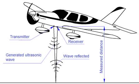
Fig. 1. Schematic view of the AVI system
operating principle
An ultrasonic pulse is formed by the
transmitter and sent periodically with repetition time T. The generated wave
after reflection from the landing plane returns to the receiver head after Tri,
(Fig. 2). The distance between the sensor and the reflection plane Hi
is equal to the product of the half-wave propagation time and propagation
velocity in the medium:
Hi=½ c TRi (1)
where TRi
is the ultrasonic wave propagation time; and c is the propagation velocity (for
air 343 m / s at 20°C). The vertical component of the landing velocity can be
determined using differential methods (Fig. 3).
Fig. 2. Ultrasonic signal in the time domain
Fig. 3. Speed determination scheme
The
measured velocity is described with the relationship:
![]() (2)
(2)
or more
accurately:
![]() (3)
(3)
where
Vi is the measured speed; L i and Li-1 are the
consecutive distances; and T is the repetition time.
The distributed pole
effectiveness of the directional transmitting head diagram is shown in Fig. 4.
Fig. 4. Distributed pole effectiveness of the
directional transmitting head
A modified AVI velocity identification and acceleration (AVI-a) system
has been developed and implemented, which measures the height of the aircraft,
the vertical velocity of the touchdown in the final phase of landing, and the
vibration amplitude of selected aircraft components. Fig. 5 shows a block
diagram and Fig. 6 shows a general view of the AVI-a system.
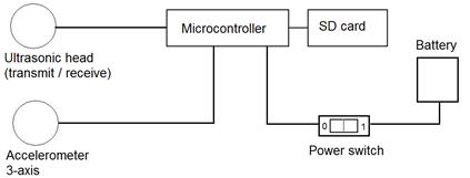
Fig. 5. Block diagram of the AVI-a system
Fig. 6. General view of the AVI-a system
The vibration acceleration measurement allows us to determine the loads
to be delivered to the aircraft during the landing and gives a better estimate
of the wear rate of the structure, which is important for determining the cause
of any landing failures. The system can be used to evaluate the art of piloting
(quantitative identification of pilot skills).
2. AVI-A SYSTEM TESTS WITH CZAJKA AIRCRAFT
BALLAST
The purpose of this AVI research was to verify the assumptions about the
system’s suitability in aviation applications.
The methodology for the study consisted of the simultaneous measurement
of distance and acceleration in the course of the falling of the ballast and
the impact on the protective barrier, which was supposed to simulate the moment
of plane touchdown. The measurement station diagram is shown in Fig. 7.
Handles were mounted on the ballast, with which it was suspended on the
ropes. The hitch was at a height of 7 m, while their other end was mounted at a
height of about 1 m.
![]()
![]()
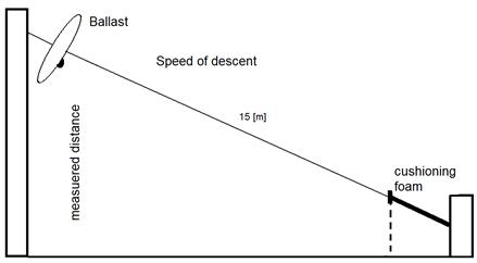
Fig. 7. The scheme of the AVI-a system for
testing
An ultrasonic transceiver head and an accelerometer measuring
acceleration in three mutually perpendicular directions, x, y, z, was placed on
the ballast. The view of the ballast with sensors and the accelerometer is
shown in Fig. 8.
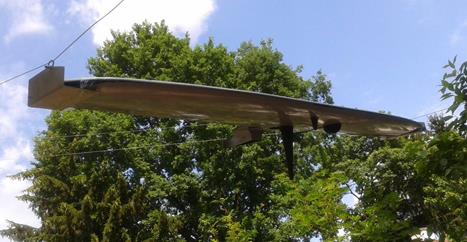
Fig. 8. View of the
ballast during tests with the AVI-a system
There were two types of tests on the station. The first was a free throw
of the ballast, while the second was a throw-in with a controlled braking
force. Simultaneously with the height measurement, the vibration of the ballast
was measured.
An example of the elevation change as a function of time for free
discharge is given in Fig. 9, while Fig. 10 shows the acceleration waveforms
for the three directions recorded during the discharge.
Fig. 9. The waveform of
height change as a function of time for a freefall
Fig. 10. Waveforms of the vibration acceleration
of three directions as recorded during discharge
In addition, tests were carried out on a
high-speed object (up to 140 km/h) to verify the operation of the ultrasound
head. The tests confirmed the possibility of using the above head during
high-speed measurements.
3. AVI
SYSTEM TEST ON SKYLEADER 600 AIRCRAFT
The AVI system was also tested under
operational conditions on the Skyleader 600 aircraft (Fig. 11).
Fig. 11. View of the
Skyleader 600 aircraft
AVI system tests were carried out at airports with different runway
surfaces: on a grass runway (Rybnik) and on a concrete runway (Kaniów).
The block diagram of the applied system is given in Fig. 12, and the
system view with ultrasonic heads is shown in in Fig. 13.
Fig. 12. Block diagram of the AVI system
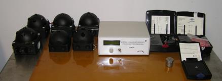
Fig. 13. View of the AVI system with ultrasonic
heads
A view of the AVI system mounted on the Skyleader 600 aircraft is shown
in Fig. 14. The heads were placed under the wing at a height of about 66 cm.
Head Head Receiver Transmitter
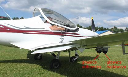
Fig. 14. Location of
transmitter and receiver head
4. TESTS RESULTS
During the measurement session, many landings were conducted under the
same weather conditions with the same pilot. It can be observed that each
landing had a different character.
Below are graphs showing the individual touchdown processes on the
concrete runway (Figs. 15 and 16) and on the grass runway (Figs. 17 and 18).
Time [s]![]()
![]()
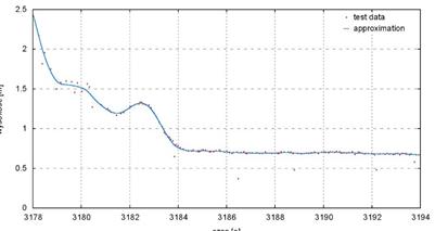
Fig. 15. Touchdown: concrete runway (Test 3)
Time [s]![]()
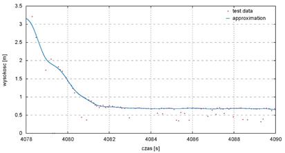
Fig. 16. Touchdown: concrete runway (Test 5)
Time [s]
![]()
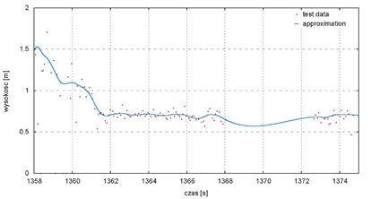
Fig. 17. Touchdown: grass runway (Test 8)
Time [s]
![]()
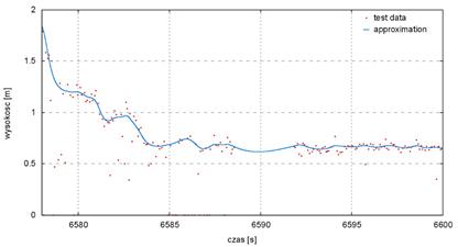
Fig. 18. Touchdown: grass runway (Test 12)
The above charts can be read for
different types of landing, i.e., slowly (Fig. 15) or faster (Fig. 16). For the
grassland runway, the measurement noise was greater than for the concrete
runway.
5.
CONCLUSION
The system can be used to assess pilotage during the landing phase in
terms of quantifying the pilot’s skills and assessing the impact of the landing
on the construction of the aircraft, as well as determining the wear rate of
the structure, which is important for establishing the cause of any landing
failure. All data for height, the vertical velocity component and the vibration
acceleration amplitude of the test element are recorded on a micro SD card,
allowing for historical data recovery and subsequent analysis.
The system can be used to:
1. Determine
the kinetic energy of the touchdown for optimal adjustment of the energy
absorber (e.g., in an adaptive pneumatic landing gear).
2. Quantitatively
evaluate the touchdown manoeuvre as a training aid for pilots.
3. Measure
the position and speed in small planes and helicopters equipped with an
adaptive chassis.
4. Track
the course of landings during training flights.
Thanks to data archiving, the AVI system allows for better estimation of
the wear rate of the structure, which is important for determining the causes
of possible failures. It can be used in light and ultralight aircraft and,
after adaptation, in unmanned aircraft. It can also be used to evaluate the art
of piloting during landing.
In the case of unmanned aircraft, it is possible to use such signals in
automatic control systems at the moment of touchdown.
References
1.
Dong X.M., G.W. Xiong. 2013. “Vibration attenuation of
magnetorheological landing gear system with human simulated intelligent
control”. Mathematical Problems in
Engineering, Article ID 242476. DOI: 10.1155/2013/242476.
2.
Mikułowski G., Ł. Jankowski. 2009. “Adaptive landing gear: optimum
control strategy and potential for improvement”. Shock and Vibration 16(2): 175-194.
3.
Mikułowski G., J. Holnicki-Szulc. 2007. “Adaptive landing gear concept-feedback control
validation”. Smart Materials and
Structures 16(6): 2146-2158.
4.
Sekula K., C. Graczykowski, J.
Holnicki-Szulc. 2013.
“On-line impact load identification”. Shock
and Vibration 20: 123-141.
Received 20.08.2017; accepted in revised form 18.10.2017
![]()
Scientific Journal of Silesian
University of Technology. Series Transport is licensed under a Creative
Commons Attribution 4.0 International License