Article citation information:
Margielewicz, J., G�ska,
D., Wojnar, G. Numerical modelling of toothed gear
dynamics. Scientific Journal of Silesian
University of Technology. Series Transport. 2017, 97, 105-115. ISSN: 0209-3324. DOI: https://doi.org/10.20858/sjsutst.2017.97.10.
Jerzy
MARGIELEWICZ [1], Damian G�SKA[2], Grzegorz WOJNAR[3]
NUMERICAL
MODELLING OF TOOTHED GEAR DYNAMICS
Summary.
This paper presents the results of computer simulations of a gear model, where
the variable stiffness of the meshing and backlash are considered. The outcome
of such assumptions is a non-linear mathematical model in which chaotic
phenomena can occur. During model studies, attention was paid to the
identification of areas limited by the physical parameters, for which the analysed
system behaved chaotically. To determine the ranges of irregular gear
behaviour, numerical procedures were used to plot the bifurcation diagram, the Lyapunov exponent, the amplitude-frequency distribution and
the Poincar� cross section.
Keywords:
dynamics; non-linear vibrations; chaos; toothed gear
1. INTRODUCTION
Heavy-duty machines, in particular
cranes, perform complex tasks with the result that heavy loads are transported
at close range. When transporting a load, it often happens that the operator is
forced to manoeuvre it to avoid collisions with surrounding obstacles. Making
safe manoeuvres is not possible without properly functioning enforcement
mechanisms. In every mechanism, there are toothed gears whose primary purpose
is to transform mechanical energy by reducing or multiplying angular speed.
Reducers used in crane hoisting mechanisms, whose ratios are in the range of 32�100, are usually performed in three
stages. However, in the range of ratios from 112�450, they are performed in four stages. Depending on the
manufacturer, two-speed gearboxes with gear ratios of 7�50 are also used in the mechanisms. Such large gears allow for
lifting loads up to 500 t. The
typical range of crane-hoisting capacity ranges from 5�50 t. The nominal torque at the gearbox output with gear ratios
from 7�450 is in the range of 12�660 kNm.
Single-stage gear units can also be used in low-level hoisting mechanisms.
The free meshing of the wheels is
ensured by the backlash and bottom clearance [17]. Their presence is one of the
main sources behind non-linearities appearing. Since
the mid-20th century there has been a growing interest among researchers in the
dynamics of non-linear systems [3,8,9]. Non-linearities
cause irregular intermittent forces in the gearboxes. It is believed that a
given phenomenon is chaotic if it is characterized by high irregularities.
Chaotic dynamics are evident when, in a two-run system, trajectories initially
located nearby expire exponentially over time [3]. Most commonly used in
computer simulations, gear models are based on non-linear differential
equations with variable coefficients. In gearing, the variation of coefficients
is mainly due to the stiffness of the meshing, which depends on the number of
pairs of teeth in the tooth contact. It is worth mentioning that the ratio of
stiffness of two-way and one-way meshing is usually in the range of 1.7 to 2 [16]. Its value depends, inter
alia, on the transmission ratio and the values of the shift coefficients [11,18,23].
The source of the excited vibrations of the cooperating pair of gear wheels is
also a deviation in the design and the position. Mostly, they are caused by
radial run-out and deviation in the tooth profile from the ideal position [15].
They are also often mapped via a function that is a superposition of several
harmonic components [7,22]. Mathematical models of toothed gears, in addition
to stiffness of the gearing, also take into account the susceptibility to
roller bearings on which the gears are mounted [25].
Studies of non-linear gear models
also deal with issues related to chaos. These analyses, inter alia, concern the
influence of individual parameters on the dynamics of the transmission [1,10,14,21].
In performed numerical experiments, the qualitative influence of the parameters
of the mathematical model characterizing single-stage gear on its dynamics was
investigated. To identify areas where chaos may have occurred, bifurcation
diagrams and charts of the maximum Lyapunov exponent
were created. It is believed that Lyapunov�s maximum
exponent is one of the more reliable indicators for evaluating the chaotic
system, as its positive values indicate the irregular behaviour of the system
under study [2]. From a theoretical point of view, Lyapunov
exponents measure the sensitivity of the studied system towards initial
conditions and are interpreted as the average rate of dissipation along the
trajectory in the phase plane [4]. The bifurcation diagrams provide
quantitative and qualitative information on the doubling of the period, while
the qualitative properties are most conveniently investigated by fractal
geometry [19]. In this sense, it is worth mentioning that the term
�bifurcation�, within chaos theory, is understood as the division of the path
of solutions [13].
2. FORMULATION OF THE MATHEMATICAL
MODEL OF SINGLE-STAGE GEARING
Gears with straight teeth were
modelled as a mechanical vibration system with two degrees of freedom. The
formulated model consists of two non-deformable discs with radii R1 and R2, whose inertial properties are mass moments of
inertia J1 and J2. The discs rotate relative
to the rigidly supported axis of rotation O1
and O2. The forces
generated in the engagement of the mating wheels are mapped in parallel onto
the joint of the spring cZ
element and dispersing element bZ. In addition, backlash 2LZ and the static error of the gearwheel cooperation e(t) have been considered. In model
studies, the gear wheel cooperation error is treated as a kinematic effect on
the cooperating teeth. The transmission is induced by the external torque M1, while the resistance
torque also affects the M2
gear. During the formulation of the phenomenological model, the influence of
errors caused by the positioning and the execution of the gears was omitted.
|
|
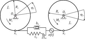
Fig. 1. Model of a toothed gear
Based on the phenomenological model,
differential equations of motion have been derived, which ultimately take on
the following form:
|
|
(1) |
It is more convenient to evaluate
the nature of the forces generated in meshing by using a reduced model with one
degree of freedom:
�
|
|
(2) |
where:
|
���������
|
wZ = z1�wS - frequency of meshing, wS - angular velocity of the motor, and z1 - number of pinion teeth.
The variable stiffness of meshing
plays a significant influence on the value of the forces acting on the gear
teeth, but is not a source of non-linearity. The main cause of non-linearity,
which occurs in numerical gear models, is the backlash 2LZ. Its presence ensures that the meshing wheels
are free to mesh and demesh. Most often, it is
modelled using non-linear functions with a so-called dead zone [12,24]:
|
��������������������� |
(3) |
The simplest and least laborious way
to identify stiffness in a tooth is to treat it as a fixed beam. This approach
provides imprecise results, but can be used to perform initial computer
simulations. This approach calculates the angular displacement of the gear
wheel caused by the force acting on the gear tooth [20]. With this information,
it is still possible to estimate the average rigidity of one- and two-way
meshes by the following relationships:
|
������ ����������������� |
(4) |
where:
![]() �- angular displacement of the wheel at one-way
mesh, and
�- angular displacement of the wheel at one-way
mesh, and ![]() �- angular displacement of the wheel at two-way
mesh.
�- angular displacement of the wheel at two-way
mesh.
Based on the above, and using the Cai formula [5,6], the variable stiffness of time function
is obtained. Modelling dynamic systems, whose properties are described by
discontinuous functions, is cumbersome. Considering the improvement in numerical
calculations, variable meshing stiffness is reproduced through the harmonic
function:
|
�������������������������� |
(5) |
where:
c0 - medium
meshing stiffness, and c1
- amplitude of the dynamic component.
To more accurately reproduce
variable meshing stiffness in the computer simulation, the discontinuous
functions shown in Fig. 2 can be expanded into a Fourier series. In view of the
efficient and effective conduct of numerical experiments, the mathematical
model in (2) was written in dimensionless form:
|
������������������������������� |
(6) |
where:
|
|

The consequence of dimensionless
writing and the introduction of a new coordinate represents the change in the
dead zone range, which is currently in the range of -1 to 1. Transforming the
mathematical model of a toothed gear in (2) to form (6) significantly
accelerates numerical calculations. This formulated mathematical model is the
formal basis for quantitative and qualitative computer simulations.
3. MODEL TESTS OF A TOOTHED GEAR
Sample model tests were carried out,
based on numerical data specifying a single-stage gear (Table 1). Model studies
were conducted using the computer program Mathematica (version 11).
Tab. 1
Parameters
characterizing the analysed system
|
Name |
Symbol |
Value |
|
Module |
|
5 [mm] |
|
Number of wheels (1
tooth) |
z1 |
14 |
|
Number of wheels (2
teeth) |
z2 |
85 |
|
Rotor mass moment
of inertia |
JS |
2.7 [kg m2] |
|
Drum mass moment of
inertia |
JB |
5.3 [kg m2] |
|
Wheel 1: mass
moment of inertia |
J1 |
0.0011 [kg m2] |
|
Wheel 2: mass
moment of inertia |
J2 |
1.12 [kg m2] |
|
Medium meshing
stiffness |
c0 |
5.03�108 [Nm-1] |
|
Amplitude of the
dynamic component |
c1 |
3.27�107 [Nm-1] |
|
Error of the gearwheel cooperation |
e1 |
0.01 [mm] |
|
Rated power of the
drive motor |
P |
12 [kW] |
|
Nominal speed of
the drive motor |
nS |
1,450 [obr/min] |
When performing computer simulations
in the formulated phenomenological model (Fig. 1), the inertia of the
electric motor rotor JS
and the rope winch drum JB were
considered. The
obtained results of numerical calculations illustrating the influence of
particular parameters of the mathematical model on the dynamics of gears are
presented in the form of bifurcation diagrams, as well as the maximal Lyapunov exponent, the time waveform of generalized
coordinates, the amplitude-frequency spectra and the Poincar�
cross sections.
|
a) |
b) |
|
|
|
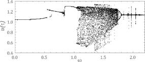
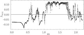
Fig. 2.� Results of calculations showing the influence of frequency on
system dynamics obtained on the assumption of the following parameters: h=0.06, a=0.065, f�r=0.044, fe=0,1 -� a) bifurcation
diagram, b) maximal Lyapunov exponent
The time waveforms,
amplitude-frequency spectra and Poincar� cross
sections are further illustrated. However, it is limited to the illustration of
strange attractors arising on the phase plane, when the value of the
corresponding frequency of meshing is changed in the cooperating gear wheels.
|
a) |
b) |
|
|
|
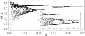
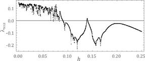
Fig. 3.� Results of calculations showing the influence of frequency on
system dynamics obtained on the assumption of the following parameters: w�1.092, a=0.065, f�r=0.044, fe=0.1 - a) bifurcation diagram, b) maximal Lyapunov
exponent
|
a) |
b) |
|
|
|
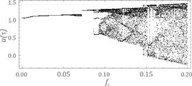
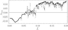
Fig. 4.� Results of calculations showing the influence of frequency on
system dynamics obtained on the assumption of the following parameters: w�1.092, h=0.06, a=0.065, f�r=0.044 - a) bifurcation diagram, b) maximal Lyapunov exponent
|
a) |
b) |
|
|
|
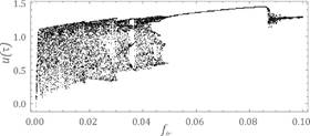
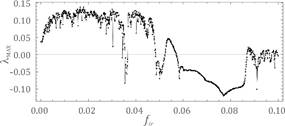
Fig. 5.� Results of calculations showing the influence of frequency on
system dynamics obtained on the assumption of the following parameters: w�1.092, h=0.06, a=0.065, fe=0.1 - a) bifurcation diagram, b) maximal Lyapunov
exponent
|
a) |
b) |
|
|
|
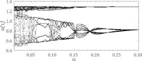
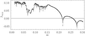
Fig. 6.� Results of calculations showing the influence of frequency on
system dynamics obtained on the assumption of the following parameters: w�1.092, h=0.06, f�r=0.044, fe=0.1 - a) bifurcation diagram, b) maximal Lyapunov
exponent
|
a) |
c) |
|
|
|
|
b) |
|
|
|
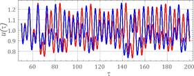
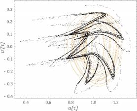
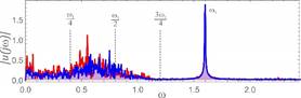
Fig. 7.� Calculation results assuming the following parameters: w=1.6, h=0.06, k1=0.065, f�r=0.044,
fe=0.1 - a) the time waveform, b)
amplitude-frequency spectra, c) Poincar� cross
section
|
a) |
c) |
|
|
|
|
b) |
|
|
|
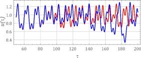
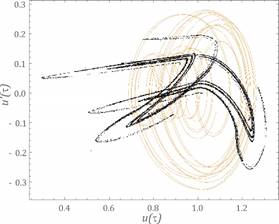
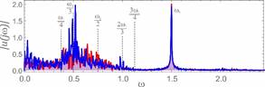
Fig. 8.� Calculation results assuming the following parameters: w=1.5, h=0.06, k1=0.065, f�r=0.044,
fe=0.1 - a) the time waveform, b)
amplitude-frequency spectra, c) Poincar� cross
section
|
a) |
c) |
|
|
|
|
b) |
|
|
|
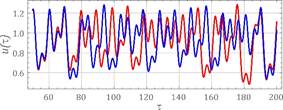
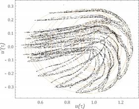
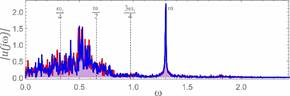
Fig. 9.� Calculation results assuming the following parameters: w=1.3, h=0.06, k1=0.065, f�r=0.044,
fe=0.1 - a) the time waveform, b)
amplitude-frequency spectra, c) Poincar� cross
section
|
a) |
c) |
|
|
|
|
b) |
|
|
|
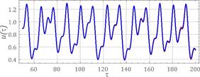
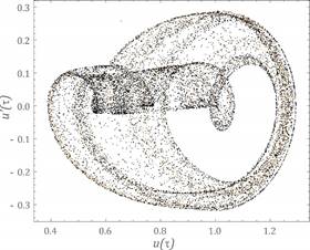
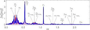
Fig. 10. Calculation results
assuming the following parameters: w=1.09246, h=0.06,
k1=0.065, f�r=0.044, fe=0. 1 - a) the time waveform, b) amplitude-frequency spectra,
c) Poincar� cross section
Graphs showing time waveforms and
amplitude-frequency spectra also show the sensitivity of the system to the
initial conditions. They were prepared with the assumption that the difference
of initial displacements equalled e=0.0001. To identify strange attractors,
the Poincar� cross section was plotted against the
background of the phase portraits.
4. ANALYSIS OF RESULTS AND CONCLUSIONS
Based on the results obtained, it
was found that, when increasing the parameter fe, representing the
cooperation of the gears error, the maximum Lyapunov
exponent was positive (Fig. 4). Increasing stiffness a and damping h in the meshing reduces the phenomenon of chaos (Fig. 3
and Fig. 6). A similar effect on gear dynamics involved a parameter
that characterized the external forces acting on the gear units (Fig. 5).
Nevertheless, with their high values, chaotic phenomena can occur in the
transmission. In the case of the frequency parameter, the chaos dominates when
the meshing frequency is greater than the resonant frequency of the gear
(Fig. 2). In the considered dynamic gear model, the ratio of the meshing frequency
to the resonant frequency was about 1.092.
This value of parameter w did not show any noticeable sensitivity to the initial conditions (Fig.
10a). On the other hand, in the amplitude-frequency spectrum, harmonic
components, which are a combination of w1 and w2, dominate (Fig. 10b). On the basis
of computer simulations, it can be stated that strange attractors appear when
there are components in the amplitude-frequency spectrum corresponding to the
frequency of induction w = w1. In addition, the entire sequence of
components up to ¾w1 is excited. The shape of the
strange attractor is dependent on the dominance of harmonics located in the
range from ¼w1 to ½w1 (Figs. 7-9). The obtained results from the
model tests indicate that, when designing working machinery mechanisms,
particular attention should be paid to the proper selection of the drive motor.
From an operational point of view, the meshing frequency is one of the most
important parameters characterizing the dynamic properties of the drive system.
Its value significantly depends on the angular velocity of the impeller of the
drive motor and the number of teeth. Therefore, the rotational speed should be
chosen in such a way that the ratio of the meshing frequency to the resonant
frequency is outside the range where the behaviour of the system is chaotic.
References
1.
Al-Shyyab A., A. Kahraman. 2005.
�Non-linear dynamic analysis of multi-mesh gear train using multi-term
harmonics balance method: sub-harmonic motion�. Journal of Sound and Vibration 279: 417-451. ISSN 0022-460X.
2.
Awrejcewicz
Jan. 1995. Matematyczne metody mechaniki.
[In Polish: Mathematical
Methods of Mechanics.] ��d�: Wydawnictwo
Politechniki ��dzkiej. ISBN
83-86453-42-7.
3.
Awrejcewicz
Jan. 1997. Tajemnice nieliniowej dynamiki.
[In Polish: Secrets
of Non-linear Dynamics.] ��d�: Wydawnictwo Politechniki ��dzkiej. ISBN 83-87198-07-2.
4.
Baker Gregory, Gollub Jerry. P. 1998. Wst�p
do dynamiki uk�ad�w chaotycznych. [In Polish: Introduction to the
Dynamics of Chaotic Systems.] Warsaw: PWN. ISBN: 8301126175
5.
Cai Y. 1995. �Simulation on the
rotational vibration of helical gears in consideration of the tooth separation
phenomenon�. Journal of Mechanical Design
117: 460-469. ISSN 1050-0472.
DOI:10.1115/1.2826701.
6.
Cai Y., T. Hayashi. 1994. �The
linear approximated equation of vibration of a pair of spur gears�. Journal of Mechanical Design 116:
558-564. ISSN 1050-0472. DOI: 10.1115/1.2919414.
7.
Ghosh S., G.
Chakraborty. 2016. �On optimal tooth profile modification for reduction of
vibration and noise in spur gear pairs�. Mechanism
and Machine Theory 105: 145-163. ISSN 0094-114X.
8.
Grega Robert, et al., 2017. �Failure
analysis of driveshaft of truck body caused by vibrations�. Engineering Failure Analysis 79:
208-215. ISSN 1350-6307.
9.
Grega Robert, et al. 2017.
�Optimization of noisiness of mechanical system by using a pneumatic tuner
during a failure of piston machine�. Engineering
Failure Analysis 79: 845-851. ISSN 1350-6307.
10.
Jingyue W., G. Lixin, W. Haotion. 2013.
�Analysis of bifurcation and nonlinear control for chaos in gear transmission
system�. Research Journal of Applied
Sciences, Engineering and Technology 6 (10): 1818-1824. ISSN 2040-7459.
11.
Jyoti D. Darbari,
Vernika Agarwal, Venkata
S.S. Yadavalli, Diego Galar,
Prakash C. 2017. �A multi-objective fuzzy mathematical approach for sustainable
reverse supply chain configuration�. Journal
of Transport and Supply Chain Management 11: 1-12. DOI:
10.4102/jtscm.v11i0.267.
12.
Kokare D. K., S.S. Patil. 2014. �Numerical analysis of vibration in mesh
stiffness for spur gear pair with method of phasing�. International Journal of Current Engineering and Technology,
Special Issue: 156-159. ISSN 2277 - 4106.
13.
Kozie� M.S. 2000. �wiczenia laboratoryjne z miernictwa
dynamicznego. [In Polish: Laboratory Exercises with Dynamic
Measurement.] Cracow: Wydawnictwo Politechniki Krakowskiej.
14.
Litak G., M.I. Friswell.
2003. �Vibration in gear system�. Chaos,
Solution and Fractals 16: 795-800. ISSN 0960-0779
15.
�uczko
Jan. 2008. Drgania regularne i chaotyczne
w nieliniowych uk�adach mechanicznych. [In Polish: Regular and Chaotic
Vibrations in Non-linear Mechanical Systems.] Cracow: Wydawnictwo
Politechniki Krakowskiej.
ISBN 978-83-7242-492-1.
16.
M�yk
Arkadiusz. 2002. �Optymalizacja w�asno�ci dynamicznych uk�ad�w nap�dowych
maszyn�. [In Polish: �Optimization of dynamic properties of
machine drive systems�.] Zeszyty Naukowe Politechniki �l�skiej, Mechanika 139. ISSN: 0434-0817.
17.
M�yk
Arkadiusz. 2002. Analiza i kszta�towanie
cech dynamicznych nap�d�w elektromechanicznych. [In Polish: Analysis and
Development of Dynamic Features of Electromechanical Drives.] Gliwice: Wydawnictwo Politechniki �l�skiej. ISBN
83-7335-078-0.
18.
M�ller
Ludwik. 1986. Przek�adnie z�bate -
dynamika. [In Polish: Toothed
Gears - Dynamics.] Warsaw: Wydawnictwa Naukowo-Techniczne. ISBN 83-204-0766-4.
19.
Peiting Heinz-Otto, Saupe Dietmar. 1996. Granice chaosu, fraktale. [In Polish: Limits of Chaos, Fractals.] Warsaw: PWN. ISBN 83-0111-784-2.
20.
Reszuta K., J. Drewniak.
2015. �Komputerowo wspomagane modelowanie dynamiki przek�adni dwudro�nej�. [In Polish: �Computer-aided modelling of two-way
transmission dynamics�.] Mechanik
7: 715-724. ISBN 0025-6552.
21.
Shuang L., W. Jin-Jin,
L. Jin-Jie, L. Ya-Qian.
2015. �Nonlinear parametrically excited vibration and active control of gear
pair system with time-varying characteristic�. Chinese Physical Society 214 (10). DOI:
10.1088/1674-1056/24/10/104501.
22.
Wang J., J. Zheng,
Z. Yang. 2012. �An analytical study of bifurcation and chaos in a spur gear
pair with sliding friction�. In
International Conference on Advances in Computational Modeling
and Simulation, Procedia Engineering
31: 563-570.
23.
Wilk
Andrzej. 1981. �Wp�yw parametr�w technologicznych i konstrukcyjnych na dynamik�
przek�adni o z�bach prostych�. [In Polish: �The
influence of technological and construction parameters on the dynamics of gears
with straight teeth�.] Zeszyty Naukowe Politechniki �l�skiej, Mechanika, z. 72. ISSN 0434-0817.
24.
Zhao X., C. Chen,
J. Liu, L. Zhang. 2015. �Dynamics characteristics of a spur gear transmission
system for a wind turbine�. In International
Conference on Automation, Mechanical Control and Computational Engineering:
1985-1990.
25.
Zhang Y., Z. Meng, Y. Sun. 2016. �Dynamic modeling
and chaotic analysis of gear transmission system in a braiding machine with or
without random perturbation�. Shock and
Vibration. Article ID 8457645. ISSN 1070-9622. DOI: 10.1155/2016/8457645.
Received 19.08.2017; accepted in revised form 07.11.2017
![]()
Scientific Journal of Silesian
University of Technology. Series Transport is licensed under a Creative
Commons Attribution 4.0 International License