Article citation information:
Krasuski, K., Ćwiklak, J. Application of the
GLONASS code observations for the designation of coordinates of an aircraft in
flight test mode: a case study. Scientific
Journal of Silesian University of Technology. Series Transport. 2017, 97, 69-80. ISSN: 0209-3324.
DOI: https://doi.org/10.20858/sjsutst.2017.97.7.
Kamil
KRASUSKI[1], Janusz ĆWIKLAK[2]
APPLICATION
OF THE GLONASS CODE OBSERVATIONS FOR THE DESIGNATION OF COORDINATES OF AN
AIRCRAFT IN FLIGHT TEST MODE: A CASE STUDY
Summary. The
aim of this article is to present the results of GLONASS positioning in
kinematic mode in air navigation. The flight experiment was conducted at Dęblin
Airfield on a Cessna 172 aircraft. The aircraft position was recovered on the
basis of the single-point positioning (SPP) method of the GLONASS code
observations. The numerical computations of aircraft coordinates were executed
in the RTKPOST library of the RTKLIB software. The standard deviations in
aircraft position in a BLh geodetic frame were checked with the ICAO standards
on civil aviation for the GLONASS system. The typical accuracy of aircraft
positioning on the horizontal plane is better than
Keywords: GLONASS; ICAO; air transport;
accuracy; SPP method
1. INTRODUCTION
The GLONASS system is part of the
GNSS systems, along with the GPS, Galileo and BeiDou systems [7]. Moreover, the
GLONASS system can be applied to a number of scientific areas as another
navigation system, e.g., in geodesy and cartography, mobile mapping,
geodynamics, geophysics, atmosphere monitoring, cosmic weather, meteorology,
telecommunication and radio communications, logistics and transport, precise
agriculture, civil engineering, GIS, time transfer and navigation. In the
navigation area, the GLONASS system is still implemented in automobiles, as
well as in marine and air navigation. Unfortunately, it is very hard to obtain
official data about standard positioning services for civil users in the GLONASS
system. In addition, the typical accuracy of the user’s position should be
higher than
The authors also present the results of GLONASS
positioning in a kinematic test in civil aviation. The kinematic test was
conducted using a Cessna 172 aircraft at the military airfield in Dęblin on 1
June 2010. The aircraft’s trajectory was recovered based on the GLONASS code
observations for the SPP method. The raw GLONASS observations were collected
via a Topcon Hiper Pro receiver, which was installed in the pilot’s cabin. The
aircraft’s coordinates and their accuracy were calculated in the RTKPOST
library of the RTKLIB software. The least-squares estimation was applied in the
adjustment processing of the GLONASS code observations at an interval of 1 s.
The article is divided into five sections: Introduction, Methodology of
Research, Research Experiment and Results, Discussion and Conclusions.
2. METHODOLOGY OF RESEARCH
In this section, the mathematical
formulations for a recovery of the aircraft position are presented. The
mathematical formulation is focused on the undifferenced positioning method,
i.e., the SPP method. The basic equations for the presented method are
expressed below [1]:
![]() (1)
(1)
where:
![]() - pseudorange value (C/A or P code)
at the first frequency in the GLONASS system, with the precise P code recovered
using the following equation:
- pseudorange value (C/A or P code)
at the first frequency in the GLONASS system, with the precise P code recovered
using the following equation: ![]() [3],
[3],
![]() - DCB instrumental
biases between P and C/A code at the first frequency in the GLONASS system (the
DCB values are distributed in the CODE Analysis Center in Switzerland [12]),
- DCB instrumental
biases between P and C/A code at the first frequency in the GLONASS system (the
DCB values are distributed in the CODE Analysis Center in Switzerland [12]),
![]() - geometric distance between the
satellite and the receiver,
- geometric distance between the
satellite and the receiver,
![]() ,
,
![]() - aircraft’s coordinates in the ECEF
frame,
- aircraft’s coordinates in the ECEF
frame,
![]() - GLONASS satellite coordinates,
- GLONASS satellite coordinates,
![]() - speed of light,
- speed of light,
![]() - receiver clock bias,
- receiver clock bias,
![]() - satellite clock bias,
- satellite clock bias,
![]() - ionosphere delay,
- ionosphere delay,
![]() - troposphere delay,
- troposphere delay,
![]() - relativistic effect,
- relativistic effect,
![]() - satellite inter-frequency code
bias (IFCB), referenced to the first frequency in the GLONASS system,
- satellite inter-frequency code
bias (IFCB), referenced to the first frequency in the GLONASS system,
![]() - receiver ICFB, referenced to the
first frequency in GLONASS system,
- receiver ICFB, referenced to the
first frequency in GLONASS system,
![]() - measurement noise and multipath
effect in the SPP method.
- measurement noise and multipath
effect in the SPP method.
In Equation
(1), the number of unknown parameters equals four (e.g., the aircraft’s
coordinates = three parameters and the receiver clock bias = one parameter).
The remaining terms in Equation (1) are modelled as follows:
- The GLONASS satellite coordinates
are calculated using the Lagrange polynomial based on the precise ephemeris
file or the applied fourth-order Runge-Kutta method based on the broadcast
ephemeris file.
- The satellite coordinates must be
referenced to the emission time of the pseudorange (e.g., the time of the
pseudorange travelling through the atmosphere and the Sagnac effect are applied
in this algorithm).
- The satellite clock bias is
calculated using the Lagrange polynomial based on the precise ephemeris file or
the applied data from the broadcast message.
- The satellite clock bias is also
corrected using information about the relativistic effect.
- The relativistic effect in the
GLONASS system can be obtained using data about the satellite position and
velocity from the precise ephemeris file or the broadcast message.
- The ionosphere delay is evaluated
using the Klobuchar model.
- The troposphere delay is estimated
using the deterministic model (e.g., Hopfield, simple or Saastamoinen).
- The measurement noise in Equation
(1) is neglected.
- The multipath effect in Equation
(1) is neglected.
- The GLONASS navigation message
does not include any information about IFCBs; the IFCB parameters are estimated
for satellites and receivers using a geometry-free linear combination;
currently the IFCB parameters are published at the website of the CODE Analysis
Center.
The unknown
parameters in Equation (1) are solved based on the least-squares estimation in
adjustment processing of the GLONASS code observations for each measurement
epoch, as per below [5]:
 (2)
(2)
where:
![]() - vector with unknown parameters,
- vector with unknown parameters,
![]() ,
,
![]() - unknown aircraft’s coordinates,
- unknown aircraft’s coordinates,
![]() - matrix of normal equation frame,
- matrix of normal equation frame,
![]() - full rank matrix,
- full rank matrix,
![]() - matrix of weights,
- matrix of weights,
![]() - misclosure vector,
- misclosure vector,
![]() - vector that includes the
difference between observations and modelled parameters,
- vector that includes the
difference between observations and modelled parameters,
![]() - standard error of unit weight a
posteriori,
- standard error of unit weight a
posteriori,
![]() - number of observations,
- number of observations,
![]() - number of unknown parameters,
- number of unknown parameters,
![]() - vector of residuals,
- vector of residuals,
![]() - standard deviations for unknown
parameters, with parameter
- standard deviations for unknown
parameters, with parameter ![]() referenced to the ECEF frame.
referenced to the ECEF frame.
The
standard deviations ![]() can also be expressed
in the BLh geodetic frame BLh, as per below [8]:
can also be expressed
in the BLh geodetic frame BLh, as per below [8]:
 (3)
(3)
where:
![]() - covariance matrix of the
aircraft’s coordinates in the geodetic frame (BLh),
- covariance matrix of the
aircraft’s coordinates in the geodetic frame (BLh),
![]() ,
,
![]() - transition matrix from geocentric (XYZ) to geodetic frame
(BLh),
- transition matrix from geocentric (XYZ) to geodetic frame
(BLh),
![]() - standard deviation for latitude,
- standard deviation for latitude,
![]() - standard deviation for longitude,
- standard deviation for longitude,
![]() - standard deviation for ellipsoidal
height.
- standard deviation for ellipsoidal
height.
3. RESEARCH EXPERIMENT AND RESULTS
In
this section, the research experiment is described and the results of GLONASS
positioning in the kinematic test are presented. The flight experiment was
conducted on a Cessna 172 aircraft at the military airfield in Dęblin on 1
June 2010 (see Fig. 1). The flight experiment was planned between 09:39:04 and
10:35:03 GPS time.
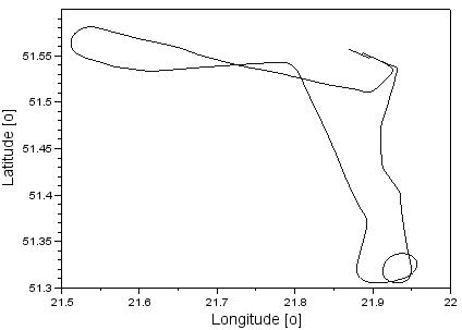
Fig. 1. The horizontal trajectory of the
Cessna 172 aircraft
The aircraft position was recovered
based on the GLONASS code observations with a time interval of 1 s. The raw
GLONASS observations were collected using a Topcon Hiper Pro receiver, which
was installed in the pilot’s cabin. The Topcon Hiper Pro receiver also saved
the GPS observations, although they were not used in the computations. The raw
GPS data were removed from RINEX file using the teqc program [2].
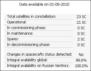
Fig. 2. Status of the GLONASS satellites’
constellation on 01.06.2010 [13]
Fig. 2 presents the status of the
GLONASS satellites’ constellation on 1 June 2010. The number of available
satellites equals 21, all of which belong to the GLONASS-M generation. In
addition, two GLONASS-M satellites were in a spare phase. The marker of the
operational GLONASS satellites is presented in Fig. 3. None of the GLONASS
satellites experienced any temporary breaks on that day [13].
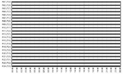
Fig. 3. Number of GLONASS satellites [13]
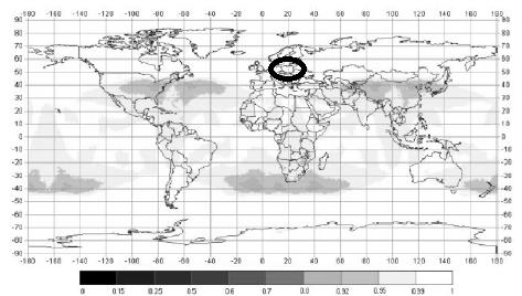
Fig. 4. Availability of the GLONASS
satellites [13]
Fig. 4 presents the status of the
GLONASS satellites’ constellation. Across Poland, the availability parameter of
the GLONASS system is over 99%, similar to ICAO standards. The number of
visible GLONASS satellites equals nine for this experiment, i.e., R01, R02,
R03, R10, R11, R13, R18, R19 and R20.
In the research experiment, only the
GLONASS code observations were applied to the aircraft position determination
process. The aircraft’s coordinates were determined based on the SPP method in
the RTKPOST module in the RTKLIB software. The RTKLIB software is an
“open-source” programme, for which the source code was written in Borland C++ language. Currently, the RTKLIB package can apply GPS,
GLONASS, Galileo, BeiDou and SBAS observations to the adjustment processing of
GNSS data. The initial parameters and models of the SPP method in the RTKLIB
software were configured as per below [11]:
- Positioning mode: single
- Elevation mask: 5°
- Source of ionosphere delay:
Klobuchar model
- Source of troposphere delay:
Saastamoinen model
- Source of satellite coordinates
and clocks: broadcast ephemeris
- Methods of estimation of the
GLONASS satellites’ position: Runge-Kutta fourth-order method
- IFCBs: based on the product from
CODE
- Relativistic effect: applied
- Phase centre offset/variation:
based on the ANTEX file
- Earth rotation correction, Sagnac
effect: applied
-
Reference frame: WGS-84 (a seven-parameter transformation between PZ-90.02 and
WGS-84 was applied)
- Computation mode: postprocessing
- Computation solution:
least-squares estimation
- GNSS system: GLONASS
- GNSS observations: L1-C/A GLONASS
code observations
- Adjustment processing: applied
- Interval of computation: 1 s
- GNSS time: GPS time, based on the
RINEX file
Figs. 5, 6
and 7 present the standard deviations of the aircraft’s coordinates in the BLh
geodetic frame. The accuracy of the latitude in the SPP method equals
In the case
of longitude, the accuracy amounts to
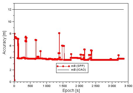
Fig. 5. Latitude accuracy of the Cessna 172
aircraft
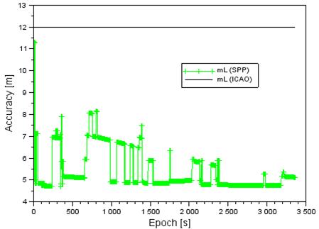
Fig. 6. Longitude accuracy for the Cessna
172 aircraft
The
accuracy of ellipsoidal height in the SPP method is about
The
obtained results of the accuracy of aircraft positioning by means of the SPP
method are of paramount importance when it comes to the certification and
handover to operation of the GLONASS system in civil aviation. The technical
standards, which have been implemented by the ICAO, are designed to determine
the possible use of the GLONASS system for civil aviation. The ICAO
recommendations published in Appendix 10, Volume I, entitled “Radionavigation
aids”, are designed to use satellite signals from satellites of the GLONASS-M
generation for the precise positioning of aircraft in air navigation. It needs to
be observed that, in civil aviation, the ICAO recommendations permit the
generally available L1-C/A signal for the GLONASS system. This signal is
modulated by using the frequency division multiple access technique for the
1.6-GHz frequency band. The limits of the accuracy of the set aircraft position
by means of the GLONASS system are specified in the technical standards of the
ICAO through the parameters of the navigation error position on the vertical
and horizontal planes. For navigation on
the horizontal plane, the limit of accuracy ranges from 5 to
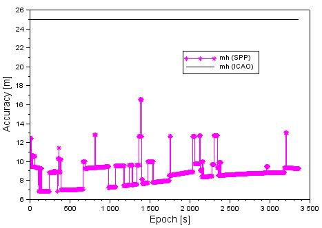
Fig. 7. The accuracy of ellipsoidal height
of the Cessna 172 aircraft
Fig. 8
presents the values of the mean radial spherical error (MRSE) parameter in 3D
space, based on the SPP solution. The MRSE parameter in Fig. 8 is estimated as
per below [10]:
![]() (4)
(4)
The average
value of the MRSE term equals
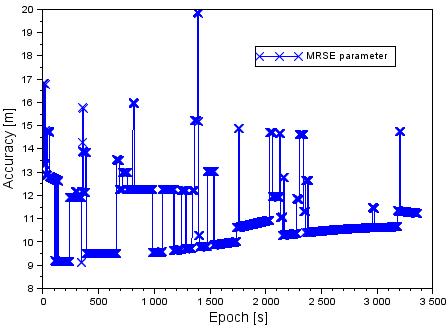
Fig. 8. The values of the MRSE parameter
4. DISCUSSION
In this
section, the accuracy of the aircraft position, based on the GLONASS solution
in a flight experiment, is compared with NPA standards for the GNSS system. In
Table 1, the accuracy of the aircraft position is referenced to the official
data of the NPA GNSS procedure in the landing phase. The ICAO recommends that
the accuracy of the aircraft position on the horizontal plane should be equal
to approximately 220 m, while the accuracy in the vertical plane is not active
for users [4,6]. In the flight experiment, the average
accuracy of the aircraft position in the horizontal plane equals
Tab. 1
The
accuracy of the aircraft position in relation to official data for
the NPA GNSS procedure
|
Parameter |
Obtained accuracy of the aircraft
from the SPP solution |
Technical ICAO standard |
|
Accuracy
of latitude |
The
average value of standard deviation for latitude in the flight test is higher
than |
The theoretical value of accuracy
of the aircraft position on the horizontal plane equals |
|
Accuracy of longitude |
The average value of standard deviation for
longitude in the flight test is higher than |
The theoretical value of accuracy
for the aircraft’s position on the horizontal plane equals |
|
Accuracy of ellipsoidal height |
The average value of standard deviation in
ellipsoidal height in the flight test is higher than |
The NPA GNSS procedure does not include the official data on aircraft
position accuracy in the vertical plane |
5. CONCLUSIONS
In this
article, the results of GLONASS positioning in the kinematic test in civil
aviation were presented and described. The kinematic experiment was conducted
using a Cessna 172 aircraft at the military airfield in Dęblin on 1 June 2010.
The aircraft’s trajectory was recovered based on the SPP method, using the
GLONASS code observations. The raw GLONASS observations were collected using a
Topcon Hiper Pro receiver, which was mounted in the pilot’s cabin. The
aircraft’s coordinates and their accuracy were calculated in the RTKPOST module
in the RTKLIB software. The least-squares estimation was applied to the
adjustment processing of the GLONASS code observations for each measurement
epoch. The accuracy of the aircraft’s position from the SPP method was compared
in this paper with the official release of the ICAO standards in civil
aviation. The aircraft position accuracy on the horizontal plane exceeded
References
1.
Cai Changsheng,
Gao Yang. 2013. “Modeling and assessment of combined GPS/GLONASS
precise point positioning”, GPS Solutions
17: 223-236. DOI: 10.1007/s10291-012-0273-9.
2.
Estey Lou, Wier
Stuart. 2014. Teqc Tutorial: Basics of
Teqc Use and Teqc Products. Copyright UNAVCO, Boulder, Colorado, USA.
3.
Gao Yang. 2008. “GNSS biases, their effect and calibration”. Paper presented at IGS
Workshop 2008. Florida, USA.
4.
Grunwald Grzegorz,
Adam Ciećko, Mieczysław Bakuła, Rafał Kaźmierczak. 2016. “Examination of GPS/EGNOS integrity in north-eastern Poland”. IET
Radar, Sonar & Navigation 10 (1): 114-121. DOI:
10.1049/iet-rsn.2015.0053.
5.
Hofmann-Wellenhof Bernhard, Herbert Lichtenegger, Elmar
Wasle. 2008. GNSS - Global Navigation Satellite Systems: GPS, GLONASS, Galileo, and More. ISBN 978-3-211-73012-6. Vienna, New York: Springer.
6.
International
Civil Aviation Organization. 2006. ICAO Standards and Recommended Practices
(SARPS), Annex 10, Volume I (Radionavigation aids). Available at: http://www.ulc.gov.pl/pl/prawo/prawomi%C4%99dzynarodowe/206-konwencje.
7.
Januszewski Jacek.
2011. “The problem of compatibility and interoperability of satellite
navigation systems in computation of user’s position”. Artificial Satellites 46 (3): 93-102. DOI:
10.2478/v10018-012-0001-2.
8.
Osada Edward.
2001. Geodesy. Wrocław: Oficyna
Wydawnicza Politechniki Wrocławskiej. ISBN 83-7085-663-2.
9.
Sanz Subirana
Jaume, Jose Miguel Juan Zornoza, Manuel Hernández-Pajares. 2013. GNSS Data Processing, Volume
I: Fundamentals and Algorithms. Noordwijk, Netherlands: ESA Communications, ESTEC. ISBN 978-92-9221-886-7.
10.
Seeber Gűnter.
2003. Satellite Geodesy. Second
Completely Revised and Extended Edition. Berlin, Germany: Walter de Gruyter
GmbH & Co. ISBN 3-11-017549-5.
11.
Takasu Tomoji. 2013. RTKLIB Ver. 2.4.2 Manual, RTKLIB: An Open Source
Program Package for GNSS Positioning. Available at: http://www.rtklib.com/prog/manual_2.4.2.pdf.
12.
The CODE Analysis Center in Switzerland. Available at: ftp://ftp.unibe.ch/aiub/CODE/2010/.
13.
Information and Analysis Center for Positioning, Navigation and Timing.
Available at: https://glonass-iac.ru/en/archive/index.php.
14.
Russian global
positioning satellites: GLONASS GPS. Available at:
http://www.spacetoday.org/Satellites/GLONASS.html.
Received 29.08.2017; accepted in revised form 30.10.2017
![]()
Scientific Journal of Silesian
University of Technology. Series Transport is licensed under a Creative
Commons Attribution 4.0 International License