Article citation information:
Budzik, G., Mazurkow, A. Modelling and testing
of dynamic properties of C0-45 turbochargers. Scientific Journal of Silesian University of Technology. Series
Transport. 2017, 97, 17-25.
ISSN: 0209-3324. DOI:
https://doi.org/10.20858/sjsutst.2017.97.2.
Grzegorz BUDZIK[1],
Aleksander MAZURKOW[2]
MODELLING
AND TESTING OF DYNAMIC PROPERTIES OF C0-45 TURBOCHARGERS
Summary. The paper presents modelling process and results of the bench tests of
the C0-45, which is a turbocharger for heavy-duty diesel engines. For
turbochargers like this, it is necessary to measure the level of vibration. This paper presents the test results for 115
turbochargers. Rotor speed during the tests varied between 25,000 and 42,000
rpm. Rotor speed during the tests on a C0-45 turbocharger varied within three
ranges, i.e., Range I: n=25,000¸32,000 rpm and a=0.5g; Range II: n=33,000¸38,000 rpm and a=1.0g; Range III: n=39,000¸42,000 rpm and a=1.5g; (g=9.81m/s2). Measurement of
vibrations was realized by a sensor located on the body of the turbocharger.
Bench tests also included measurement of key charge parameters such as the
amount of mass trapped, mean flow velocities, turbulence level, gas pressure,
temperature and oil flow. The results are presented in the form of diagrams
showing the amplitude of the acceleration function with regard to the rotor’s
RPM. Research shows that using the correct parameters in construction and
technological processes of assembly are very important for the effective
functioning turbochargers.
Keywords: turbocharger; construction
parameters; dynamic properties; level of vibration; rotor speed
1. INTRODUCTION
Turbochargers are mainly used to
convert exhaust gases energy into compressed air energy. The air is pumped into
a fuel supply system in a combustion engine.
The basic operating parameters of a
turbocharger are: compression ratio, airflow, gas temperature, a maximum
rotating speed and a level of vibration. The operational accuracy of a rotating
set is tested with the use of an engine test stand.
2. TURBOCHARGER TEST STANDS
Each turbocharger is tested with the use of an engine
test stand (Fig. 1). This facility checks the assembly quality and cooperating
parts. Operational characteristics and the measurement of vibrations are also
determined.
The main elements of an engine test stand are:
-
turbocharger mounting brackets
-
combustion chamber with a fuel system
-
installation of air
-
lubrication system
-
measuring and control system
-
exhaust system
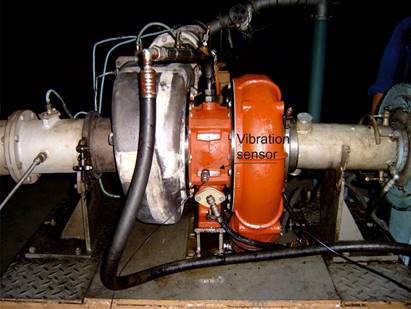
Fig. 1. Stand
test for C0-45 turbochargers and the vibration sensor
Measurement of vibrations is performed by a sensor
(Fig. 1), which estimates the level of acceleration of a rotating unit system
in a turbocharger. The sensor is located on the body of the turbocharger.
The level of vibrations is a basic requirement that
guarantees a proper operation and the usage of a turbocharger. Measurement is
performed during a set motion. Rotor speed for a C0-45 turbocharger varies
between 25,000 and 42,000 rpm. Commissioning requirements determine the values
of maximal acceptable accelerations, depending on the rotating speed of a
turbocharger rotor.
3. TEST STAND RESULTS
Operating parameters values for a C0-45 turbocharger
are:
-
compression ratio
2.8:1
-
airflow 31÷76 [m3/min]
-
gases temperature
700 [°C]
-
maximal rotating
speed nwmax=42,000 [rpm]
Values of acceptable vibrations during tests of
rotating speeds for a turbocharger C0-45 are varied across three ranges:
-
Range I: 25,000≤nw≤32,000
[rpm], adop≤0.5g
-
Range II:
33,000≤nw≤38,000 [rpm], adop≤1.0g
-
Range III:
39,000≤nw≤42,000 [rpm], adop≤1.5g
where g=9.81 m/s2 equates to gravitational acceleration.
Factory acceptance tests have demonstrated that a
large number of turbochargers, even when featuring suitable parameters
(consumption, compression ratio), is not able to work.
During acceptance testing of 115 turbochargers, it was
found that measured accelerations varied between 0.01 and 10.0 g. It should be
noted that maximal acceptable accelerations can reach up to 1.5 g.
The reason why turbochargers are not used concerns
excessive measured values of acceptable accelerations. Having tested all
turbochargers, 33% of them do not meet the requirement concerning boundary
vibration values (Fig. 2).
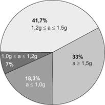
Fig. 2. Percentage
of turbochargers according to vibration range level
Turbochargers that meet commissioning requirements can
be divided into two groups. The first group includes turbochargers that
work in upper ranges of vibrations (0.8g<adop≤1.5g) and the
second group includes turbochargers that work in lower ranges (adop≤0.8g).
The diagram (Fig. 3) describes vibrations in an rpm function for the first
group of turbochargers, whereas the second group is presented in Fig. 4.
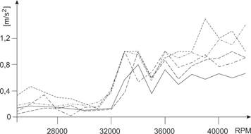
Fig. 3. Level of vibration of turbochargers (adop≤1.5g) during the rpm
function
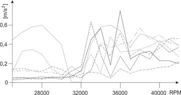
Fig. 4. Level
of vibration of turbochargers (adop≤0.8g)
during the rpm function
Having examined vibration measurements for the first
group in the range 0≤nw≤42,000 rpm, we can note two resonant
zones. The first zone appears during the rotating speed nw=32,000 rpm, while
the second zone appears close to a speed equal to nw=38,000 rpm.
Ranges of resonant zones agree with the operating ranges of turbochargers.
The second group of turbochargers features small
vibrations values. In this case, there is only one resonant speed, which
appears at higher rotational speeds, i.e., nw=32,000÷37,000 rpm.
4. ANALYSIS OF TEST STAND RESULTS
Taking into account the testing results, we can see
that the right choice of construction and technological parameters of a
rotating set can guarantee the correct operating parameters of turbochargers.
Turbochargers with excessive acceptable vibrations
were disassembled in order to find reasons for this situation. Then, rotating
units were balanced again. The assembled turbochargers were tested once more.
It was not always possible to achieve the right
operating parameters of a turbocharger during another assembly because of
vibrations level. Therefore, these actions were repeated to achieve the proper
operating parameters.
5. THEORETICAL MODEL OF A ROTATING SET IN A
TURBOCHARGER
To assure the correct work of a turbocharger, it is
important to find sources of excessive vibrations and minimize them.
Theoretical bases for rotor construction and explanations for vibrations in
rotating sets are discussed in [1,4,7].
Test stand studies have shown that the main cause of
rotational motion disturbances in a rotating set within a turbocharger is
centrifugal fictitious forces, which appear because the axis of rotation does
not agree with the main axis of a rotating set. These different axis locations
are caused by the imbalance in rotating masses. The disequilibrium allows
centrifugal fictitious forces to appear. These forces constitute outer driving
forces and could lead to resonance.
It should also be mentioned that gravitational forces,
which act upon rotating parts, can be the source of vibrations.
Another cause of vibrations can be related to medium
resistance in the area where rotors are working.
The bearing mounting plays an essential part in rotor
operations. Slide bearings with an embedded rotor could be the reason for
hydrodynamic forces, which in turn contribute to self-activating vibrations in
the oil layer [2,3,4,5,6,8]. In the discussed turbocharger, a rotating unit is
supported in hydrodynamic bearings with a floating ring bearing.
The following reasons for vibrations have been
accepted by the author for the purposes of a design model:
-
imbalance in
turbocharger rotors
-
the mass of parts
in a rotating unit
-
floating ring
bearing masses
-
radial clearance
in a lateral slide bearing with floating ring.
To explain these reasons shown above, the author has
designed a dynamic model for the rotating unit of a turbocharger (Fig. 5).
Rotors in a turbine and on the compressor side have different masses and
different unbalance values. In this model, each bearing has been modelled,
including a floating ring bearing mass. Moreover, attention has been paid to
rigidity and damping factors, as well as both oil films’ ability concerning
vibration damping. The motion of the
model is examined in two planes, i.e., 0XZ and 0YZ. The rigidity factors (cx,
cy) and damping factors (dx, dy) are treated
as coupled values.
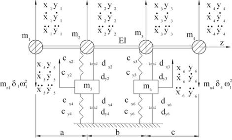
Fig. 4. Model of a
rotating set
A mathematical version of the presented physics model
is constituted by motion equations, which are written according to the force
method for each mass of this model in planes OXZ and OYZ and can be expressed
thus:
![]()
![]() (1)
(1)
where matrixes take the form:

Values describing the work of a rotating
set are shown in Tab. 1. The influence of structural parameters on static and
dynamic characteristics is described in Tab. 2, while Table 3 presents
published results of the influence of unbalance on displacement amplitude in
knots of rotating sets.
Tab. 1
Given parameters for calculations of a rotating unit
|
Bearing loads [N] |
||||||
|
Fw=2=400-600 |
Fw=3=370-550 |
|||||
|
Rotational speed of a shaft [rpm]= |
||||||
|
n1=w1/2p=300-500 |
||||||
|
Concentrated masses in particular nodes [N∙s2/m] |
||||||
|
m1=5.0 |
m2=0.3 |
m3=0.25 |
m4=2.0 |
|||
|
Masses of floating ring bearings [N∙s2/m] |
||||||
|
m5=0.055-0.1176 |
m6=0.055-0.1176 |
|||||
|
Geometric parameters of rotating unit |
||||||
|
a=0.055 [m] |
b=0.075 [m] |
c=0.045 [m] |
Ix=0.15∙10-6
[m4] |
|||
|
Material constants |
||||||
|
E=1.915∙1011[N/m2] |
ISO VG 150 |
|||||
|
Unbalance of rotating masses [N∙s2] |
||||||
|
Nw1=0.18∙10-4,
0.88∙10-4 |
Nw4=0.5∙10-5 |
|||||
|
Geometry of bearings with a floating ring |
||||||
|
Slide bearings width [m] |
||||||
|
Bw1=0.017 |
Bw4=0.017 |
|||||
|
Radius of journal [m] |
||||||
|
(RJ1)w1=10.82-15.82∙10-3 |
(RJ1)w4=10.82-15.82∙10-3 |
|||||
|
Floating ring bearing thickness [m] |
||||||
|
(gp)w1=2.97-12.97∙10-3 |
(gp)w4=2.97-12.97∙10-3 |
|||||
|
Relative clearance of inner bearing [‰] |
||||||
|
(y1)w1=6.28-15.5 |
(y2)w4=2.8-12.4 |
|||||
Tab. 2
Influence of structural parameters
on the operating parameters of a rotating set
|
Characteristics |
|||
|
Static |
Dynamic |
||
|
h1,2,min ¯ |
T1,2 max ¯ |
p1,2max ¯ |
Ap(x5,
x6, y5, y6) ¯ |
|
yi ¯ |
yI ¯ |
yi |
yi ¯ |
|
C*R
¯ |
C*R
|
C*R
|
C*
¯ |
|
|
|
|
mp
|
|
B*
¯ |
B*
|
B*
|
B*
|
|
|
|
|
Nw¯ |
|
Tz
|
Tz
¯ |
Tz
¯ |
|
Tab. 3
The influence of unbalance on
displacement amplitude in knots of rotating sets
|
Unbalance of rotating masses |
Displacements amplitude in knots of rotating sets
[m] |
|||||
|
x1 |
x2 |
x3 |
x4 |
x5 |
x6 |
|
|
Task 1 Nw1=0.18∙10-4, Nw4=0.5∙10-5 |
2.267∙10-6 |
1.266∙10-6 |
1.162∙10-6 |
2.344∙10-6 |
0.2682∙10-6 |
0.2351∙10-6 |
|
Task 2 Nw1=0.88∙10-4, Nw4=0.5∙10-5 |
6.908∙10-6 |
6.19∙10-6 |
8.431∙10-6 |
13.16∙10-6 |
1.577∙10-6 |
2.076∙10-6 |
|
|
y1 |
y2 |
y3 |
y4 |
y5 |
y6 |
|
Task 1 Nw1=0.18∙10-4, Nw4=0.5∙10-5 |
3.641∙10-6 |
3.185∙10-6 |
2.971∙10-6 |
3.203∙10-6 |
0.5455∙10-6 |
0.3799∙10-6 |
|
Task 2 Nw1=0.88∙10-4, Nw4=0.5∙10-5 |
17.63∙10-6 |
22.04∙10-6 |
29.43∙10-6 |
34.82∙10-6 |
3.441∙10-6 |
4.067∙10-6 |
6. CONCLUSION
Table 2 shows that the influence of structural
parameters on static and dynamic characteristics can be, on the one hand,
contradictory (e.g., the feed oil temperature and the minimal height of a
lubricant gap) or, on the other hand, compatible (e.g., the feed oil
temperature and the oil film maximum temperature).
The
unbalance is an influence factor on displacement values (Table 3). In Task 1,
the unbalance was Nw1=0.18∙10-4
[N∙s2]; however, in Task 2, it was Nw1=0,88∙10-4
[N∙s2]. Having compared these two tasks, it can be seen that
in the Knot 4 displacements, the amplitude increases 11 times for the
coordinate y4. The smaller values of displacements appear in Task 1.
The professional literature and
published results show that vibrations appear during the construction stage,
particularly during parts formation or turbocharger assembly. Subsequent
research will deal with the misalignment of bearings on a turbine and the
compressor side or mistakes made to the shape of bearing bushes and their
influence on the level of vibrations in a rotating unit.
References
1.
Buluschek Bruno.
1980. Das Schwimmbüchsenlager bei stationärem Betrieb. Doctoral thesis. Zürich:
ETH. No. 6527,0000.
2.
Domes Bernd. 1980.
Amplituden der Unwucht - und
Selbsterregen Schwingungen Hochtouriger mit Rotierenden und nichtrotierenden
Schwimmenden Büchsen. [In German: Amplitudes
of Unbalance and Self-raising Vibrations at High Speed with Rotating and Non-rotating
floating cans.] Dissertation. Universität Karlsruhe.
3.
Fink Peter.A.
1970. Das Schwimmbüchsenlager unter
instationärer Belastung. [In German: The Floating Bush Bearing Under Transient Load.] Dissertation.
Zurich: ETH.
4.
Kiciński Jan.
2005. Dynamika wirników i łożysk
ślizgowych. [In Polish: Dynamics of
Rotors and Plain Bearings.] Gdańsk: Wydawnictwo Instytutu Maszyn
Przepływowych PAN. ISBN 8388237063.
5.
Krause Reinhold.
1987. Experimentelle Untersuchung eines
dynamisch beanspruchten Schwimmbüchsenlagers. [In German: Experimental Investigation of a Dynamically
Loaded Swimming Pool Bearing.] Dissertation. Zürich: ETH. DOI
10.3929/ethz-a-000403016.
6.
Chin-Hsiu Li, S.H.
Rohde 1980. “On steady state and dynamic performance characteristics of
floating ring bearings”. ASME Journal of
Lubrication Technology 103 (3): 389-397. DOI 10.1115/1.3251687.
7.
Muszyńska A. 1979.
“Modelowanie wirników”. [In Polish: “Rotor modelling”.] IV training course
from the Dynamics of Machines series, Jabłonna 5-10 Listopada 1979.
8.
Zhang W. “Dynamic
instability of multi-degree-of-freedom flexible rotor system due to full annular
rub”. In Vibrations Rotating Machinery,
International Conference, Heriat - Watt University, Edinburgh, 13-15 September
1988.
Received 20.08.2017; accepted in revised form 11.10.2017
![]()
Scientific Journal of Silesian
University of Technology. Series Transport is licensed under a Creative
Commons Attribution 4.0 International License