Article citation information:
Bisták, M., Brumerčík, F., Lukáč, M. Weighing
systems in traffic. Scientific Journal of
Silesian University of Technology. Series Transport. 2017, 97, 5-15. ISSN: 0209-3324.
DOI: https://doi.org/10.20858/sjsutst.2017.97.1.
Marek BISTÁK[1],
František BRUMERČÍK[2],
Michal LUKÁČ[3]
WEIGHING
SYSTEMS IN TRAFFIC
Summary. This article presents a brief overview of
weighing systems and devices designed to facilitate fluent and safe road
traffic. The number of vehicles on roads is perpetually on the rise, resulting
in increased wear of road surfaces. This is why weight check gates have widely
been implemented to check the speed and weight of a vehicle against what is
permitted by law. A cheaper, albeit more time-consuming, traffic weighing
alternative would involve weighing points using weighbridges or mobile axle
scales. The second part of this article examines the development of an axle
scale. The design and calculation works were performed with the use of the Creo
Parametric CAD system and the ANSYS Workbench FEM system.
Keywords: dynamic weighing system axle scale;
load cell vehicle
1. INTRODUCTION
The primary expectation of transport
infrastructure is the assurance of traffic safety and fluency [10,11,12]. To be
able to meet this requirement, motorways, roads, bridges and other traffic
structures must have their pavement in an appropriate technical condition. The
growing number of vehicles increases the load on roads and their speed of their
deterioration, resulting in an impaired road pavement quality. In order to
maintain roads in a good condition, in addition to ensuring regular road
maintenance and repair, it is necessary to exclude, or impose limitations on,
the traffic of unfit categories of vehicles. Such vehicle categories could
include those failing to meet technical requirements (in terms of dimensions,
weight etc.), as well as overloaded trucks exceeding the permitted total mass.
To achieve this, statutory weight
limits have been established by law for each vehicle category. The
implementation of the new legislation has been accompanied by the development
of technical devices to check compliance with the limits. Since it is not
feasible to have all vehicles stopped and weighed at a single point, it has
been necessary to develop a system that will be able to determine the weight of
a vehicle, within a reasonable range of accuracy, while the vehicle is in
motion. Vehicles suspected of non-compliance with the weight limitation
regulations will thus be identified and can be safely stopped, with their mass
checked by means of a mobile axle weighing system or a weighbridge in a
suitable place.
2. VEHICLE WEIGHING SYSTEMS AND
DEVICES
Two weighing methods are recognized: dynamic
weighing and static weighing.
Static method
The static method requires the
vehicle to be in a static state on the scale; more specifically, where a
weighbridge or a small mobile scale is employed, either the whole vehicle or
the measured wheel, respectively, must be motionless. What is measured is the total
mass transmitted from all axles to the wheels over a 15-s time span. The
measured impulse is then processed and evaluated by the control electronics.
The weight reading is visible on a display or an external monitor.
Dynamic method
This method is used in high-speed
weight-in-motion (HS-WIM) systems and low-speed weight-in-motion (LS-WIM)
systems (more often referred to as axle weighing systems). With a HS-WIM
system, the vehicle is weighed as it passes over two or three sensors sunk in
the road pavement; the weighing is performed at speeds up to 250 km/h
(intervals of 1 s) without the driver noticing what happens. The measured
signal is processed within 0.5 s and the result that is obtained is either the
total mass or the load on each axle of the vehicle.
In the latter case, a number of axle
scales corresponding to the number of vehicle axles is set on a firm floor. The
measurement is performed as the wheels of each axle of the vehicle pass over
the axle scales at a speed of 10 to 15 km/h at intervals of 30 or 60 s. The
resulting weight of the vehicle (or weight per wheel or per axle) is calculated
from the acquired time course records.
2.1. High-speed weight-in-motion
system
The system is used on motorways and
expressways for the purposes of control monitoring the vehicle traffic flow.
The system checks compliance with the statutory speed and weight limits.
A WIM system is composed of a gate
with ANPR cameras, laser scanners and, possibly, other electronics to improve
the accuracy of the control cycle.
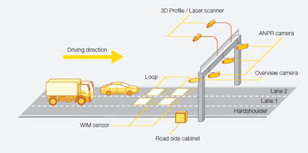
Fig. 1. High-speed weight-in-motion
system
Two to three piezoelectric sensors
(of the Kistler Lineas quartz type)
are installed in the pavement to weigh, with a high accuracy, a vehicle in
motion at up to 250 km/h. The control unit with evaluation electronics is
installed in a cabinet in a safeguarded location near to the check gate.
Kistler Lineas quartz sensor
The sensor consists of a weighbridge
mounted onto an aluminium alloy section. Two quartz plates are placed in the
middle of the section to generate an electric impulse when loaded (based on the
piezoelectric principle), with the signal directly proportional to the
gravitational force of the wheel. The sensor is isolated from lateral forces by
means of a special flexible material.
The load measurement accuracy is
neither influenced by the tyre type, tread pattern or pressure, nor the number
of tyres. In the case of dual tyres, the sensor generates a single signal,
which is expressed as a single-wheel load, equivalent to the sum of the two-wheel
loads.
The sensor is inserted in a slot in
the pavement and fixed by a grouting compound (supplied by the manufacturer)
made of an epoxy material and sand. The surface is then ground to a level [3,5].
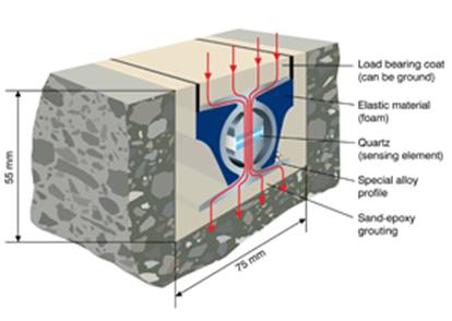
Fig. 2. Kistler Lineas quartz sensor
design
Table 1. Technical parameters of the
Kistler Lineas 9195E sensor
|
Technical parameter |
Value |
|
Accuracy class [%] |
2 |
|
Range wheel load [kN] |
0-150 |
|
Load-bearing capacity on the
sensor surface [N/mm2] |
6 |
|
Operating temperature range
[ºC] |
-40÷70 |
|
Temperature coefficient
(sensitivity) [%/ºC] |
-0.02 |
|
Sensor length [m] |
1.5/1.75/2.00 |
|
Sensor length [m] |
40/100 |
|
Degree of protection |
IP 68 |
|
Position |
Stationary |
2.2. Weighbridge
A weighbridge is a device designed
to measure the weight of a passenger car, a truck, or a truck and trailer
combination. There are two basic design types: an above-ground version and a
pit version.
An above-ground weighbridge
comprises load cells, evaluation electronics, a weighbridge, an approach ramp
and a departure ramp. It is usually designed as a steel structure with a
weighing capacity between 1 and 80 t and a length ranging between 5 and 20 m.
The scale may be positioned on either a paved ground or a concrete road surface
that has a sufficient load-bearing capacity and is appropriately level. Where
the device is to be installed on a concrete road, concrete bases are usually
provided for the load cells. The design must reasonably provide for the
approach of a vehicle.
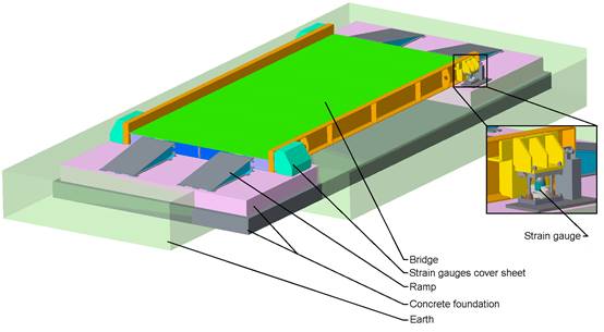
Fig. 3. Above-ground weighbridge
A pit-mounted road weighbridge does
not pose any obstacle and is, therefore, usually installed in locations where
the available space is limited by adjacent structures. The installation depends
on the prefabricated pit, the location layout and the slope of the road.
Lengths vary within the range of 8 to 24 m. The bridge may be designed as
either a steel structure with a load-bearing capacity of 60 t or a steel shell
filled with high-performance concrete with a load-bearing capacity of up to 120
t.

Fig. 4. Pit weighbridge
2.3. Axle measurement system
An axle measurement system comprises
a control and evaluation unit and an even number of axle scales (two scales for
each vehicle axle to be weighed).
An axle scale is made of an
aluminium weighbridge, which is set on four, six or eight load cells. The
measurement range is up to 3, 6, 10, 12 or 20 t. Smooth passage over the bridge
is facilitated by approach and departure ramps with a structure made of steel
or a hardened material [1].
The evaluation unit is enclosed in a
protective case made of a strong, but flexible, impact resistant copolymer to
ensure safety. During the measurement (using a static method, or a dynamic
method for LS-WIM systems), the unit processes the electric signal generated by
the scales, which is transmitted via 15-m cables or Wi-Fi. The resulting weight
reading is shown on the display or printed in a paper-based measurement report.
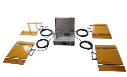
Fig. 5. Axle measurement system
3. AXLE SCALE DEVELOPMENT
The customer who initiated the
project requested six mobile scales to be developed for an existing control and
evaluation unit. The system was required to be able to weigh any vehicle with a
mass of up to 40 t and no more than three axles in any place with a paved
surface.
3.1. Requirements for the axle scale
development
Requirements for the axle scale
development are:
- Axle scale measuring range: up
to 10 t/wheel
- Maximum dimensions of a scale
with ramps: (WxLxH): 500x11,000x60 [mm]
- Scale capacity: vehicles with
two or three axles up to 40 t in weight
- Manufacturability within the
company’s own capacities
- Mobility and simple handling
- Reasonable project costs
3.2. Design of the chosen axle scale
alternative
The axle scale system incorporates a
weighbridge and load cell units. The weighbridge is designed as an aluminium
alloy plate deck with weight reduction slots, two handles and sliding locks to
secure the passage ramps against movement. Two wheels are provided on the
right-hand side to facilitate the handling. The scale electronics is mounted on
the bottom side of the deck in a steel enclosure. The enclosure partially
enhances the rigidity of the deck. Four load cell units are screw-mounted to
the deck.
A load cell unit contains a HBM C9C
load cell, which is mounted in a slot of the unit base. Three screws are
provided on the base, turned by 120º to secure the sensor against movement
in the x-axis and y-axis directions (offset). A steel roller is fitted between
the top cover and the measurement surface of a tension meter to provide the
single-point force transmission. The top cover is fixed to the base by two screw
rods, each with two nuts [4,6].
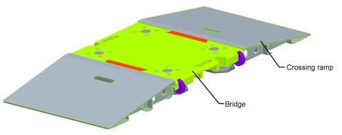
Fig. 6. Axle scale
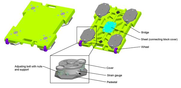
Fig. 7. Axle scale with a load cell
unit
Table 2. Technical parameters of the
designed axle scale
|
Description |
Unit/characteristics |
|
Weighing capacity [kg] |
10,000 |
|
Readability - scale division [kg] |
5 |
|
Nominal sensitivity [mV/ V] |
2±0.2% |
|
Function |
Weighing (static/dynamic) |
|
Weighing speed [s] |
≤10 |
|
Deck dimensions (WxL) [mm] |
500x400 |
|
Dimensions of the scale with ramps: (Wx LxH)
[mm] |
500x1,100x60 |
|
Scale weight [kg] |
35 |
|
Structure material |
Steel/aluminium |
|
Standard operating temperature [°C] |
-10÷40 |
|
Operating temperature limit [°C] |
-40÷70 |
|
Data transmission |
Cable |
|
Position |
Mobile |
|
Protection class |
IP 68 |
3.3. Simulation
The proposed axle scale design was
subjected to an FEM-based strength analysis in the Static Structural module of
the Ansys Workbench software. The static weighing of a truck was simulated. The
simplified simulation model incorporated a weighbridge (material: aluminium
alloy) and a cabling enclosure (material: steel). The contact surface between
the deck and the truck wheel was modelled using an FEM mesh of 23,278 elements
with 43,209 nods. The contact surface was loaded with a force (F) of 100,000 N (the gravity transmitted
by a wheel from the axle). The seats of the load cell units were fitted by
means of a fixed support and a frictionless support. The model also provides
for the gravity of the weighbridge itself (gravitational acceleration (g) of 9.8066 m/s; see Fig. 8).
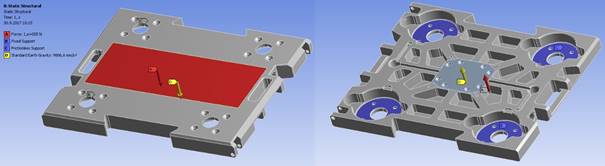
Fig. 8. Scale simulation model
3.4. Results
The outcome of the FEM simulation is
the maximum plate deflection of 0.221 mm and tensions ranging from 25 to 100
MPa, which occur in the centre of the bottom side of the scale (Figs. 9-10).
The agreed yield strength of the chosen aluminium alloy material is Remin=260 MPa and ultimate
tensile strength is Rm=675
MPa. The agreed yield strength of the chosen steel material is Remin=180 MPa and ultimate
tensile strength is Rm=380
MPa. The former implies that the proposed axle scale design meets the strength
requirements.
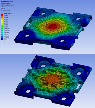
Fig. 9. FEM simulation result

Fig. 10. FEM simulation result
4. DISCUSSION
The FEM simulation in ANSYS
Workbench demonstrated that the proposed axle scale design meets the strength
requirements based on the anticipated loads. The FEM analysis results are
consistent with the strength calculations performed at the device development
stage. Hence, one pair of test prototypes was fabricated and tested in
practice. The test prototypes passed the tests successfully [2].
5. CONCLUSION
The first part of this article
provided a brief overview and description of weighing systems and devices
currently used in traffic applications. The second part of the article
described the development of an axle scale that meets all the requirements of
the customer. As a particular advantage, the scale features a mobile design,
easy installation and a favourable cost. The scale is able to weigh trucks with
two or three axles and a total mass of up to 40 t.
References
1.
Skrucany Tomas, Kendra Martin, Skorupa Milan,
Figlus Tomasz. 2017. “Comparison of chosen
environmental aspects in individual road transport and railway passenger
transport”. Procedia
Engineering 192: 806-811. DOI:
https://doi.org/10.1016/j.proeng.2017.06.139.
2.
Skrucany Tomas, Sarkan Branislav, Figlus
Tomasz, et al. 2017. “Measuring of noise
emitted by moving vehicles”. MATEC Web of
Conferences 107: 00072. ISBN:
978-1-5108-4114-7. DOI: https://doi.org/10.1051/matecconf/201710700072.
3.
IRD. “Lineas Quartz WIM Sensor by Kistler”. Available at:
http://www.irdinc.com/pcategory/wim-scales--sensors/lineas-quartz-wim-sensor-by-kistler.html.
4.
HBM. “C9C”. Available at:
http://www.hbm.cz/produkty/snimace-sily/c9c/
5.
Weighing Review. “Kapsch presents new weigh in motion
solution at ITS Europe”. Available at:
http://www.weighingreview.com/2013/12/kapsch-presents-new-weigh-in-motion.html.
6.
Walzscale. “Axle scale wheel weighers”. Available at:
https://www.walzscale.com/portable-wheel-axle-load-weighers.
7.
Samociuk W., Z.
Krzysiak, M. Szmigielski, J. Zarajczyk, Z. Stropek, K. Gołacki,
G. Bartnik, A. Skic, A. Nieoczym. 2016. “Modernization of the
control system to reduce a risk of severe accidents during non-pressurized
ammonia storage”. Przemysł Chemiczny
95 (5): 1032-1035. ISSN 0033-2496. DOI: https://doi.org/10.15199/62.2016.5.29.
8.
Samociuk W. Z.
Krzysiak, G. Bartnik, A. Skic, S. Kocira, B. Rachwał, H. Bąkowski,
S. Wierzbicki, L. Krzywonos. “Analysis of explosion hazard on propane-butane liquid
gas distribution stations during self tankage of vehicles”. Przemysł Chemiczny. 96 (4): 874-875.
ISSN 0033-2496. DOI: https://doi.org/10.15199/62.2016.5.29.
9.
Faturik L., Trsko L.,
Hrcek S., Bokuvka O. 2014. “Comparison of structural design in
high and ultra-high cycle fatigue regions”. Transactions
of FAMENA. 38 (4): 1-12. ISSN 1333-1124.
10.
Droździel Paweł,
Monika Wińska, Radovan Madleňák, Paweł Szumski. 2017. “Optimization of the position
of the local distribution centre of the regional post logistics network”. Transport Problems 12 (3): 42-74. ISSN
1896-0596. DOI: https://doi.org/10.20858/tp.2017.102.3.4.
11.
Droździel Paweł,
Iwona Rybicka, Radovan Madleňák, Aleksandra Andrusiuk, Dariusz Siłuch. 2017. “The engine set
damage assessment in the public transport vehicles”. Advances in science and technology Research Journal Vol. 10 (1):
117-127. ISSN 2299-8624. DOI: https://doi.org/10.12913/22998624/66502.
12.
Niels van Oort, Rob van Nes. 2017. ”Regularity analysis for optimizing
urban transit network design”. Public
Transport 1(2): 155-168. https://doi.org/10.1007/s12469-009-0012-y.
Received 11.09.2017; accepted in revised form 02.11.2017
![]()
Scientific Journal of Silesian
University of Technology. Series Transport is licensed under a Creative
Commons Attribution 4.0 International License