Article citation information:
Brodzik, R. The influence of thermal loads on modern road concrete
pavements in Poland. Scientific Journal
of Silesian University of Technology. Series Transport. 2017, 95, 27-37. ISSN: 0209-3324. DOI: https://doi.org/10.20858/sjsutst.2017.95.3.
Robert BRODZIK[1]
THE INFLUENCE OF THERMAL LOADS
ON MODERN ROAD CONCRETE PAVEMENTS IN POLAND
Summary. This article presents the
opportunities for the development of road concrete pavements in Poland. The
analysis of the prospects for evolving a new type of concrete pavement, based
on continuous reinforcement, has been performed. The advantages and
disadvantages, in terms of functionality, strength and economy, have been
analysed. The evaluation of stress and displacements in the analysed
continuously reinforced concrete slabs, involving the use of the finite element
method (FEM), has been performed on selected temperature distributions derived
from thermal loads. Based on the analysis of adopted decompositions, the use of
the FEM to assess the effectiveness of the continuously reinforced pavements
has been proposed.
Keywords: continuously reinforced concrete pavement; numerical
modelling; thermal loads; concrete slab; temperature.
1.
INTRODUCTION
The Programme
for National Road Construction 2014-2023 (with a View to 2025) is a
document that defines the objectives regarding the development of road
infrastructure. It includes a schedule for the realization of investments,
aimed at their accomplishment and highlighting funding sources and the amount
of planned expenditures. The main aim of the programme is to build a consistent
and modern system of roads in the country, which will provide the effective
functioning of road passenger and cargo transport. The programme costs, which
are estimated at PLN 107 billion, will be used to build about 3,900 km of
highways and expressways, as well as 57 ring roads. Furthermore, PLN 51.8
billion will be allocated to the maintenance and modernization of existing
roads. In order to achieve the above goals, missing parts of expressways and highways
will be completed, while selected parts of national roads will be refurbished
and ring roads constructed, which will improve the traffic flow in the urban
centres that are the most affected by loaded transit traffic. The crucial aim
of the above programme is to build, by 2023, over 880 km of concrete roads in
the national road system [3,7,10].
On the new financial horizon, it is assumed that
approximately three quarters of new roads will be built using traditional
bitumen technology, whereas approximately one quarter will use concrete
pavements. In 2016, upon the completion of parts of concretized expressways and
highways, as well as making them available for use, their total length will be
less than 580 km, which will only constitute 6% of all highways.
2. DEVELOPMENT OF
CONCRETE PAVEMENTS IN POLAND
Concrete pavements date back to ancient times, when
the Romans started using cement to bond the layers that roads were made of. The
first contemporary concrete pavements were created at the beginning of the 20th
century in the US, with the first concrete pavement comprising a concrete slab,
which was 0.175 m thick, 1 mi long and 4.5 m wide, and had stretching gaps with
wooden inserts positioned every 7.5 m. The first concrete highways appeared in
1939 in Germany, while Poland developed a new technology for constructing road
surfaces for the first time in 1912 in Cracow [6,13].
Since the early 20th century, concrete pavements
have gone through a period of significant evolution and technological
revolution, including a reduction in the distance between transverse gaps up to
5 m, the implementation of a road foundation of concrete slabs, the obligatory
use of aeration admixtures of concrete, and the careful use of fresh concrete.
The advantages of concrete pavements have been
recognized by many countries, mainly in Western Europe. Germany is the country
with the longest and the most significant tradition in Europe regarding the
creation of concrete pavements. Currently, Germany has 12,000 km of highways,
with as much as 40% of such a grade of roads made with the use of concrete
technology. In the context of European countries, Belgium should also be
mentioned, where concrete pavements constitute nearly 90% of the main road
system. The main advantages of concrete pavements can be divided into three
categories: technical (long-term endurance of pavements), economic (a lower
overall cost of creation and maintenance) and social (the majority of the
materials used are produced in the country).
There are additional advantages of concrete
pavements, which were taken into account while planning future road investments
in Poland:
-
Resistance to
deformation, especially rutting: it is planned to build concrete roads where
heavy traffic load occurs, in particular, where the ratio of passenger traffic
is similar to truck traffic (truck traffic equates to approximately 5,000
vehicles per day)
-
A much longer
period of using concrete pavements (over 30 years) compared to asphalt
pavements (about 20 years of use)
-
Concrete pavements after
applying surface treatment do not require additional funding, even over a
period of up to 20 years (or up to nine years in the case of asphalt pavements)
-
Increasing the
number of contractors, both domestic and international, with experience
regarding the possibility of realizing new tasks using concrete technology
Currently, concrete pavements compete with asphalt
ones at the executive stage, as the former are poorer in terms of endurance.
While comparing other aspects of both types of the surface, concrete pavements
are characterized by greater durability over a long period of their use (they
do not require repairs or replacements for up to 50 years). Concrete pavements
are appreciated by drivers, as they are properly designed and textured, as well
as lesser deformation (lack of rutting), thus guaranteeing greater safety,
driving comfort and decreased fuel need. In turn, brighter-coloured concrete
pavements and increased reflexivity improve visibility, especially at night.
Regarding concrete mixtures used for surfaces, industrial by-products and waste
products can be used (cement with fly ash, open-hearth slag), which not only
eliminate the need for their storage, but also reduce the need for new
materials, thereby saving natural resources [5,13,14].
According to the Board of the Generalna Dyrekcja
Dróg Krajowych i Autostrad (GDDKiA), or the General Directorate for National
Roads and Motorways, once the Programme
for National Road Construction has been implemented after 2023, there will
be over 22,000 km of roads in total, including 4,611 km of highways and
expressways. Regarding the national road system, there will be 20,660 km of
asphalt roads (94%) and 1,350 km of concrete roads (over 6%) (Fig. 1). The
decision of the GDDKiA regarding the construction of 810 km of roads using
concrete technology is surprising in the context of historical data; within the
last 20 years, only 600 km of roads of this type have been built. The current
change in attitude is the result of observing experienced road managers in
other countries and the similarity of costs in the construction of both
concrete and asphalt roads. Meanwhile, the development of concrete roads
involves searching for new and improved construction techniques, implementing
new technologies, and conducting related research.
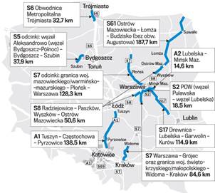
Fig. 1. Expressways and highways to be built with
the use of concrete surface technology. S6: Tri-city metropolis ring road, 32.7 km; S5
sections: Aleksandrowo junction (Bydgoszcz-North), Bydgoszcz-Szubin, 37.9 km;
S7 sections: Mazovian/Mazurian border-Warmia Provinces-Płońsk-Warsaw, 128.3 km;
S2: POW (Puławska junction-Lubelska junction), 18.5 km; S7: Warsaw-Grójec
and the border of Świetokrzyskie/Lesser Province of Widoma-Cracow, 84.6 km
3. CONTINOUSLY
REINFORCED CONCRETE PAVEMENTS
After more than century of experience regarding the
use of road concrete pavements, the following types of pavements are available:
-
Unreinforced and
non-interconnected pavements
-
Unreinforced
interconnected surface and anchored pavements
-
Reinforced pavements
with interconnected gaps
-
Prestressed
concrete pavements
-
Prefabricated
pavements
-
Complex pavements
(mixed): concrete foundation upon which a thin layer of a mineral is placed;
asphalt mixture or a concrete layer placed on existing asphalt pavement (white topping)
-
Continuously
reinforced pavements without transverse gaps [13,14]
In the context of construction technology at a
global level, the practical use of concrete pavements concerns the following
types: dowel and anchored, unreinforced and non-interconnected, complex
pavements (mixed) and continuously reinforced. The latter type is undoubtedly
the most popular in the US and EU countries (namely, England, Belgium and
France). The main disadvantage of this method is the higher cost of construction
(about 5 to 8%), which has been a significant barrier to its use in Poland. In
terms of road concrete pavements in Poland, however, it can be observed that
continuously reinforced pavements include the following advantages:
-
High levels of
driving comfort: a lack of dilatation means that there is no prevalence of
curling
-
Lower maintenance
and operation costs in relation to other types of pavements, with regard to the
limitation of dilatation gaps
-
The lack of the
adverse phenomenon known as so-called “pumping water in gaps” (penetration of
water into the subsoil does not occur)
-
The significantly
long period of their usage
The general rules for constructing continuously
reinforced pavements are based on the transverse reinforcement disposed at
between 0.1 and up to 0.23 m, situated in the middle of the concrete slabs’
thickness. Reinforcement bars are usually placed on props (Fig. 2) or by means
of specialized machines designed for this purpose. During the operation,
capillary fractures appear, which are 0.2 mm wide, reaching to a depth of 1 to
2 cm from the surface of the concrete. According to repair technology, it is
assumed that such pavements may be covered with a thin layer of a new
bituminous surface in the future (in approximately 30 years’ time) without the
need to incur expenses for its repair.
One of the first experimental parts of a
continuously reinforced road concrete pavement was constructed at the section
of the A4 highway near Kąty Wrocławskie. The contractor was a consortium
comprising Joint Venture Kirchner/Bogl/Berger, which is the main contractor of
the A4 highway, and the GDDKiA department in Wrocław. While testing a new
pavement, a new continuously reinforced section, which was 1 km long and 11 m
wide, with only two oblong gaps, was made. This section was built as a “testing
ground” before a more comprehensive implementation of a new type of surface in
Poland [4].
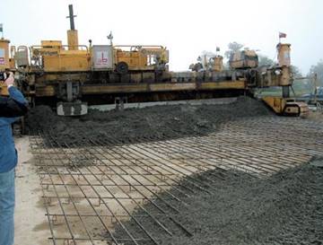
Fig. 2. The works conducted during the construction of a continuously
reinforced concrete highway
4. THERMAL LOADS OF CONTINUOUSLY REIFORCED
CONRETE PAVEMENTS
Concrete pavements are affected,
apart from the external forces caused by movement on them, by internal forces
generated in the pavements themselves, due to changes in atmospheric
temperature referred to as thermal forces. Apart from stresses coming from
wheels, thermal stresses, caused by a change in temperature on the pavement and
the bottom of a concrete slab, can be distinguished. There are several methods
for calculating the rigid surface, in which the criterion may be, for instance,
allowable deflection, allowable deformation of the subsoil or an allowable load
of the subsoil [1]. The theoretical studies on concrete pavements are mainly
based on the Westergaard method. The following point is an attempt to present
the possibilities of supporting classical methods for designing modern concrete
pavements with the use of numerical methods. Such support can be used to verify
the main construction parameters of a pavement, e.g., the thickness of a
pavement, the type and grade of the used concrete, the types of gaps, or the
type of road foundation. On the basis of the knowledge about temperature
distribution in concrete pavements, an idea has been proposed whereby it is
used in calculating the strength of the continuously reinforced concrete
pavements by taking a numerical approach.
The values of stresses in
continuously reinforced concrete pavements, caused by a change in temperatures,
should be maintained with such limitations in order to avoid uncontrolled
cracking of concrete slabs. Searching for optimal solutions for a proper
functioning of concrete pavements is a difficult task to perform, due to the
fact that fulfilling all the criteria must involve a compromise between
economy, durability and safety. Below, an example is given in terms of how
reinforced slabs, which are thermally loaded, can be tested (modelled) in such
a way where all the decisive factors affecting surface durability can be
properly selected.
Due to a large number of factors
affecting the durability of concrete constructions, it is necessary to develop
a numerical model with the most optimal assumptions and solutions related to
the actual ones. Previous strength analyses of concrete pavements were based on
the assumptions, whereby a concrete slab rests on an elastic foundation with
specified rigidity, while there is a lack of friction between the foundation
and the slab resting on it [2]. The current state of knowledge regarding the
impact of thermal loads on the durability of concrete pavements has inspired
research on the role of friction between the slab and the road foundation [6,8].
The current empirical and theoretical considerations on rigid slabs, subjected
to thermal load, have shown that, regardless of the accepted gradient of
temperatures, a free slab made of concrete takes a characteristic shape, which
resembles a bowl. The theoretical flexion of the slab, in the case of a
positive gradient, is presented in Fig. 3.


Fig. 3. Free slab with specified
weight and temperature distribution
Temperature fluctuations cause a change in
volume in slab pavements. In the case of steady temperature influences on the
whole thickness of a slab, axial deformations are created, while, in the case
of unsteady temperature distribution, flexion of the slab occurs. In
theoretical terms, a homogenous isotropic body, supported in a statistically
determined way, is subjected to a temperature field, which is a linear function
of the Cartesian coordinates that are deformed during a state of stresses equal
to zero [12]. In actual cases, when a slab cannot be easily deformed because of
its own weight, the friction and reaction of subsoil or the limitations
presented by other slabs, temperature stresses appear in the slab. Combining
such stresses with those coming from other additional loads, e.g., wheel
pressure can lead to a situation in which the presenting maximum stresses
exceed the values of allowable stresses, which in turn leads to damage to the
slabs, such as scratches or cracks.
The current state of knowledge on the
temperature distribution in concrete pavements, although relatively poor,
confirms the legitimacy of the above use of simplifications in a significant
way. The results of the research on temperature distributions in airport slabs,
under different climate conditions in Poland, as well as research conducted on
national road or airport concrete pavements [1,9], reveal that the climate and
its changeability, as opposed to the thickness of the slab, particularly
determine the distributions and occurring temperature gradients. The
significant changeability climate within Poland means that, from the point of
view of durability analyses, knowledge about the occurrence of actual
temperature distributions is necessary for measuring cycles in the long run.
If it is assumed that the difference
in temperature fluctuations in summer and winter on two following consecutive
days is as high as 30°C, it is necessary to perform a daily analysis of the
occurring stresses and deformations of the slab. The perfect tools for
conducting such analyses are programs based on the FEM, which additionally
allows for a detailed analysis of not only the influence of the size of the
gradient, but also the nature of temperature distributions in terms of slab
thickness.
5. ANALYSIS OF THE DISCRETE MODEL
This study presents an example of
numerical simulation with the use of a solid model using the FEM. The MSC
Nastran for Windows system was used to determine the movements and stresses in
continuously reinforced concrete pavements with static loads for a chosen field
of temperatures.
Modelling reinforced concrete poses
a significant number of problems caused mainly by the structure and properties
of the material. Reinforced concrete constructions combine two materials of a
different quality, namely, concrete and steel. Steel is a relatively homogenous
and well-tested material, while concrete is a composite of aggregate, sand,
cement and water, which reveals microvoids. Even for small deformations, there
is physical non-linearity. Concrete indicates high levels of endurance in terms
of compression and minimum levels for stretching in relative terms. In the
stretched areas, concrete has tendencies to become scratched and, when
compressed, to be crushed, which changes the properties of the material. In
general, the reaction of reinforced concrete is non-linear involving complex
laws of behaviour. The procedures for calculating the FEM in reinforced
concrete are based on incremental iterative methods.
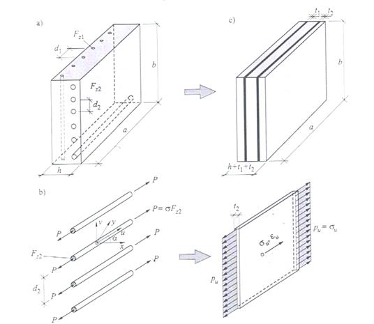
Fig.
4. The replacement model of a reinforced concrete shield [12]
In the analysed model of the
reinforced concrete shield, as shown in Fig. 4, the arrangement of reinforcement
bars is replaced by a slab element of thickness. As a result, the reinforced
concrete shield converts to a layer shield, with a layer of concrete, which is
h thick, and steel, which is t1, t2 thick, assuming that
there is full cooperation between the two materials, which means that the
compatibility of movements and deformations on their touching takes place. The
model of a reinforced concrete airport slab was made using the Femap program.
The particular stages of construction of the model are:
-
Creating
a square plane sized 10x10 [m] and providing the material properties for steel
and concrete (Table 1) [4].
Table 1. Material properties
of concrete and steel
|
Material |
Concrete |
Steel |
|
Young module [MPa] |
32,000 |
210,000 |
|
Poisson ratio [-] |
0.7 |
0.3 |
|
Density [g/mm3] |
2.4E-9 |
7.85E-9 |
-
Dividing
a plane into 10,000 finite elements and providing the third dimension of a slab
by drawing, at the height of 0.3 m, a solid consisting of 60,000 elements.
-
Removing
nodes placed at the bottom part of the solid to a distance of 0.1 m in order to
create elements of the GAP type in order to replicate the reaction of the
subsoil to the reinforced concrete. The created geometric model, sizeD
10x10x0.3 [m], is the only slab of a continuously reinforced concrete pavement that
is surrounded by all four sides by the other slabs.
-
Two
layers of fabric, composed of steel rods with a diameter of 10 mm, were placed
in a model of concrete. In order to make trusses, rod-type elements were used.
Rods are used in the analysis of truss constructions, which include axial
stresses (compression, stretching), apart from bending.
Top and bottom reinforcement Gap-type elements 3D elements

Fig. 5. Solid model of a slab with
marked reinforcement
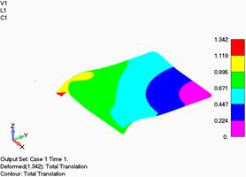
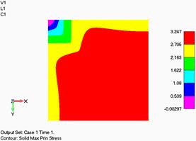
The present example is only part of the entire
analysis of thermal loads with regard to the impact of daily temperature
fluctuations on displacements and stresses in continuously reinforced concrete
pavements with the use of numerical analyses. To simulate the operation of
reinforced concrete at negative temperatures, a load in the form of a positive
gradient of temperature of -16/0°C was used, where the lowest temperature occurs at the bottom of
a slab. According to the map of displacements below, it is shown that
the negative temperature at the bottom part of the plate causes its shrinkage,
whereas higher temperatures in the upper layers cause its stretching. Maximum
displacements occur at the free corner of the slab. The greatest maximum
stresses mainly occur at the bottom of the slab, within a layer in which the
lowest temperature and the subsoil are affected (Fig. 6).
|
|
|
|
Fig. 6. Finite displacements and
deformations [mm] and maximum main stresses at the |
|
In the case of loads with a positive gradient of temperature within a
range 0/-16°C, the lowest temperature occurs mainly in the upper layer of a
slab, which causes the
shape of deformation to be reversed (Fig. 7).
|
|
|
|
Fig. 7. Entire displacements and
deformations [mm] and maximum main stresses |
|
6. CONCLUSION
The overall analysis of the results
and their comparison with other concrete pavements, including unreinforced and
interconnected [1,2] types, in terms of the implementation of higher usable
loads and increased traffic, highlights the need to use new, stronger and safer
surfaces and, in turn, modern calculation methods for determining optimal
constructions.
According to the previous numerical analysis, it can be concluded that:
-
The presented analysis performed in the study
indicated the possibility of using professional FEM programs for the entire
analysis of the state of displacements and stresses in slabs and dowels.
- The use of reinforced concrete slabs
provides the possibility for avoiding the use of dilatation in slabs, which
prompts the need to use dowel joints in the weakest places within surface
constructions.
- Greater analysis enables a selection
of examples, which, due to strength and safety reasons, are the most beneficial
- The complex nature of the occurring
stresses in the vicinity of reinforcement requires additional analyses with the
use of models on a different scale.
References
1.
Dacko M., R.
Brodzik. 2008. “Numeryczna analiza wpływu obciążeń termicznych na stan przemieszczeń
i naprężeń betonowych płyt lotniskowych.” Biuletyn WAT 2: 23-43. [In Polish: “Numerical analysis of the effect
of thermal stress on the state of displacement and stress of airport concrete
slabs”. WAT Newsletter 2: 23-43]. ISSN
1234-5865.
2.
Dacko M., R.
Brodzik. 2007. “Numeryczna analiza betonowych dyblowanych płyt lotniskowych”. Drogownictwo 6: 196-202. [In Polish: “Numerical
analysis of airport concrete slabs”. Road
Construction 6: 196-202]. ISSN: 0012-6357.
3.
El-Rashidy
R.A., S. Grant-Muller. 2016. “The evaluation of redundancy for road traffic
networks”. Transport 31(41): 427-439.
DOI: http://dx.doi.org/10.3846/16484142.2016.1255913.
4.
EN 206: 2014. Concrete - Requirements, Properties,
Production and Conformity. Warsaw: Polish Committee for Standardization.
5.
Janulevičius
A., G. Pupinis, J.s Lukštas, V. Damanauskas, V. Kurkauskas. 2017. “Dependencies
of the lead of front driving wheels on different tire deformations for a MFWD
tractor”. Transport 32(1): 23-31.
DOI: http://dx.doi.org/10.3846/16484142.2015.1063084.
6.
Nita P.
2005. Betonowe nawierzchnie lotniskowe:
Teoria i Wymiarowanie Konstrukcyjne. [In Polish: Airport Concrete Surfaces: Theory and Structural Dimensioning].
Warsaw: ITWL. ISBN 8391433765.
7.
National Road Construction
Programme/Ministry of Infrastructure and Construction. National Road Construction Programme for 2014 to 2023 (with a View to
2025). Available
at: http://mib.gov.pl/2-program_ budowy_drog_krajowych.htm.
8.
Paleczek W.
2001. “Analiza tarcia płyty betonowej o podłoże pod wpływem jej zmian
termicznych.” Drogownictwo
3: 68-72. [In Polish: “Analysis of
friction of the concrete slab on the ground under the influence of the thermal
changes”. Road Construction 3:
68-72]. ISSN 0012-6357.
9.
Petho L., P. Bryant, J. Jones, E. Denneman 2016.
“EME2 pavement and mix design”. Road & Transport Research 25(4).
ISSN: 1037-5783.
10.
Petruccelli
U., S. Carleo. 2017. “Cost models for local road transit”. Public Transport 1-22. DOI: 10.1007/s12469-017-0162-2.
11.
Polish
experiences with concrete pavements without transverse slots”. Available at: https://www.gddkia.gov.pl/userfiles/articles/d/dylatacje-nawierzchni-betonowych_10814/2007_2_30-33.pdf.
12.
Rakowski G.,
Z. Kacprzyk. 2016. Metoda Elementów
Skończonych w Mechanice Konstrukcji. Warszawa: Oficyna Wydawnicza
Politechniki Warszawskiej. [In Polish: Finite Element Method in Structural
Mechanics. Warsaw:
Warsaw University of Technology Publishing House]. ISBN 978-83-7814-471-7.
13.
Szydło A.
2004. Nawierzchnie Drogowe z Betonu
Cementowego. Kraków: Polski Cement Sp. z o.o. [In Polish: Road Surfaces of Cement Concrete.
Cracow: Polish Cement Sp. o.o.] ISBN 838947803X.
14.
The World of Concrete Roads Made with Concrete technology: Achievements and
Challenges. Available at:
http://www.swiatbetonu.pl/realizacje/drogi.
Received 20.02.2017; accepted in revised form 17.04.2017
![]()
Scientific Journal of Silesian
University of Technology. Series Transport is licensed under a Creative
Commons Attribution 4.0 International License