Article citation information:
Markiewicz, T., Kaczmarczyk, Ł., Fabiś, P. Influence of intake system
modification on the formula student engine power. Scientific Journal of Silesian University of Technology. Series
Transport. 2017, 94, 139-149. ISSN: 0209-3324. DOI:https://doi.org/10.20858/sjsutst.2017.94.13.
Tomasz MARKIEWICZ[1],
Łukasz KACZMARCZYK[2], Paweł FABIŚ[3]
INFLUENCE OF INTAKE
SYSTEM MODIFICATION ON THE FORMULA STUDENT ENGINE POWER
Summary. This paper is a summary of the design and
workmanship of the formula student engine intake vehicle, for simulation
research projects were conducted on the intake system. In the process, the most
favourable model system was selected, which was capable of producing a
satisfactory range of the characteristics of the engine. For chosen models, the
intake system was also determined in terms of its impact on the power and
torque of the test vehicle, which was driven by a four-cylinder engine with a displacement
of 0.6 dm3.
Keywords: Formula Student, intake,
engine power
1. INTRODUCTION
In classical internal combustion piston
engines, the function of the intake system was to bring refrigerant to the
cylinder engine while maintaining the smallest possible flow resistance, with
the aim of obtaining a large ratio of filling cylinders. The flow resistance
factor depended on the shape of the intake manifold, the length and shape of
the intake ducts, and the air filter, which is an indispensable piece of
equipment in the intake system. The intake system of the internal combustion
engine was designed in such a way as to provide a suitable amount of air
to the engine during its operational cycle at any speed. When designing the
intake system for not charge engines,
which predominantly operate under negative pressure, it should be taken into
account that the wave motions are generated as a result of the movement of the
piston towards the bottom dead-centre position. However, in the case of
supercharged engines, which almost always work under hypertension, it is
important to carefully select the size of the plenum and the size of the inlet
channels at the design stage [14]. Properly designed intake systems should
allow for the uniform filling of all cylinders.
2. INLET SYSTEM OF THE TURBO ENGINE
The role of the intake manifold is
to supply air to the head of the spark-injection engine, while the amount of
moved air is adjusted by a throttle valve, which is part of the system. An
essential element of the intake manifold is an air chamber, which acts as a
plenum from which the individual cylinders absorb air. Runners, or short intake
channels, represent the second element, which are an extension of the inlet
head and combine the opening of the plenum. In the case of the plenum, it is
necessary to take into account the following important factors:
-
capacity
-
uniformity
of the air supply to the individual cylinders
-
shaping
the opening (inlet) of the individual runners to achieve the maximum flow [2]
The basic shape of the intake
manifold is determined by its use. Typically, the manifold is followed by a
damper, which is placed in front of the so-called air chamber, along with the
plenum, which supplies air to all the cylinders.
One advantage of the damper cylinder
is the smaller flow losses, which means that it is more suitable to use maximum
power. In the case of a throttle being placed before the manifold, accuracy is
increased, such that you can control the fuel injection and ignition at low
engine speeds, which makes this solution more suitable for road vehicles. A
preferred situation has also been designed for the intake manifold of a road
vehicle in such a way that the damper is placed centrally between the channels
of [1].
The most important role of the
plenum is to compensate the airflow to the individual cylinders. Unfortunately,
car manufacturers use a compact, aesthetically pleasing layouts, locating the
air intake on one end. This is not a problem at the design stage when topping
up the engine plenum, but when the airflow starts to rapidly increase in real
situations, a large disturbance ensues, which results in uneven delivery to the
air cylinder [2]. The arrangement of individual dampers with a single throttle
involves two different applications, but with many features in common. In both
cases, the inlet, which takes air to the intake ports, should ideally comprise
short runners into the combustion chamber. The size of the cone relative to the
inlet runners should be prudently selected.
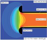
Figure 1 shows how the shape of the
intakes of the runners impacts on the speed of the airflow. On the left side,
you can see the speed of the flow in the event of the termination of a simple
tube, while the right tube forms a conical or bell shape [9].
The length of the runners has a
significant impact on the amount of air that enters the combustion chamber when
the intake valve is opened and the engine is not running under pressure (top
up). In turbocharged engines in general, the best results are obtained using
long runners, which will result in a wide range of flat torque curves at low
speeds, while the turbocharger will maintain a relatively high power at the end
of the curve [1]. The literature contains information certifying that the
runner is a tool for controlling the engine, given that the diameter and the
length influence the shape of the power curve.
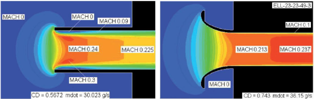
Fig. 1. Comparison of velocity flows for a simple inlet (left side) and
a cone inlet (right side); mdot: mass
flow per second [9]
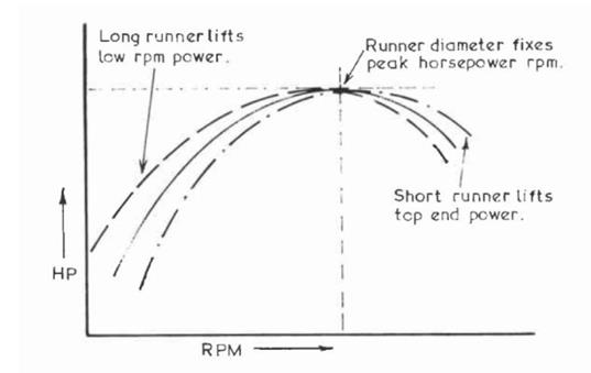
Fig. 2. Chart of the influence of the diameter and the length of a
runner on engine power [2]
In principle, the diameter will
involve a fixed rotation, in which the engine produces maximum power to the
extent that the thick runner allows the engine to freely download air at high
speed, while reducing power to the lower range. The length of the channels
enables the extension of the power curve in the vicinity of the point
determined by their diameter (Fig. 2). Short runners work in an opposite way:
i.e., lower power and torque in the lower range help the engine to maintain
power through the peak [2]. One of the important points in the design of the
intake manifold is the connection between plenum and runners, which is the
place where the inlet openings to the runners should be chosen carefully, with
the most preferred combination resulting in the formation of a hole in the
bell-shaped inlet, or “trumpet” [1].
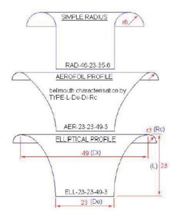
Fig. 3. Signing and shape of inlet ends [9]
The construction of the bell inlet
or so-called “trumpet” in the internal combustion engine’s end runner intake
piston has been copiously addressed in the technical literature. Modern
computational fluid dynamics offer the possibility or even the ability to carry
out computer simulations to determine the optimal shape of “trumpets”. Figure 3
shows three types of bell-shaped inlet runner, which have been analysed. Each
type of bell is characterized by fundamental values such as L (length), Do
(diameter output), Di (diameter input) and R (radius zone) (Fig. 4). There are
different bell types: they may involve a straight pipe, the normal radius of an
aerodynamic profile or that of an elliptical profile. During Blair’s analysis,
a wide range of diameters and dimensions was tried and tested for each type of
bell. Figures 6a-c represent the Mach number (speed of particles) for a normal
radius and an elliptical profile.
|
a) |
b) |
c) |
|
|
|
|
|
Fig.
4. Velocity stream flows and their decomposition for: a) fillet pipe, b)
elliptic profile and c) straight pipe [9] |
||
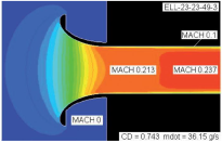
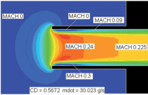
Simple rounding (Fig. 4a) shows a
significantly smaller contraction stream, which is evident for a straight pipe
(Fig. 4c). In contrast, an elliptical profile hardly narrows the stream, which
means that the flow is smooth and even. Additionally, as shown in Figure 4c,
when the tube terminates in a straight, sharp dissection, the influence
coefficient is 0.5672 and the measured mass flow rate us 30,023 g/s. As seen in
Figure 4a, when the inlet end is rounded with an ordinary radius, the influence
coefficient is 0.719 and the mass flow is 34.83 g/s. In Figure 6b, when the
bell is more refined, the elliptical profile’s drag coefficient is 0.743 and
the measured mass flow is 36.15 g/s. Considerable increases are observable in
the flow rate (27%) and the mass flow (16%) due to the addition of even a
simple rounding at the end of the inlet tube. A properly designed bell inlet runner
has a better flow rate of 3.5% compared to the normal rounding runner
connection with a plenum manifold. In terms of design, it is noted that a low
and large outer diameter bell mouth is the most optimal solution. The length L
of the bell should be equal to the initial diameter Do, while the entry
diameter Di should have a starting material diameter of 2.13. While the
literature does not provide any analysis of rounding, authors have nevertheless
suggested that rounding should have a diameter input of 0.08 [9]. Based on all
the information collected while designing the intake and its components, a
Student Formula-class first-intake manifold vehicle, known as WT-02, was created.
3.
INLET MANIFOLD
CONSTRUCTION FOR THE FORMULA STUDENT CAR
The object of the research is the
Formula Student racing class vehicle WT-02, equipped with a four-cylinder,
four-stroke spark-ignition engine, which has a capacity of 600 cm3.
Although this engine was originally powered by a carburetted system, in the
course of adapting the vehicle, the engine was converted to a multipoint
injection system.
|
|
|
|
Fig. 5.
View of the car and engine |
|
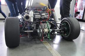

During the project construction, in
order to increase the dynamic qualities of the vehicle, a charging system using
a turbocharger was applied. The test engine and vehicle are shown in Figure 5.
The students involved on the project
made modifications to the engine intake system, while the inlet manifold was
designed using the SolidWorks CAD program. The priority was to create a
modified intake manifold, which would result in a high-power supercharged
engine and be characterized by low flow resistance.
|
|
|
Fig. 6.
Inlet manifold (Version I) before optimalization |
Fig. 7.
Inlet manifold (Version I) after optimalization |
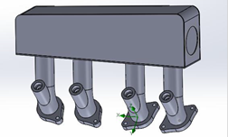
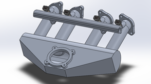
We originally used a compact
manifold (Version I) (Fig. 6), so that the entire intake system would fit in
the frame of the vehicle and satisfy the requirements of the Formula Student
competition rules. This involved a charge air cooler mounted on the right side
of the vehicle, which also determined the location of the intake manifold. The
manifold was attached directly to the throttle and fuel strip using fuel
injectors. After analysing a number of solutions in the literature on the
design of an intake manifold, we selected the design as shown in Figure 7. In
this manifold, we changed where the throttle was fixed and used a bell-shaped
inlet at the entrance to each runner. The use of such a solution should allow
for a reduction in the coefficient of flow resistance.
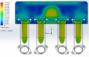
4. FLOW SIMULATION RESULTS
Flow simulations were carried out
for two intake manifolds. The analysis was carried out in relation to the inlet
side manifold (Version I) and the central inlets (i.e., “trumpets”) that had
formed in the so-called runners (Version II). In time-mapping the engine and
the first road tests, it was noted that, in the engine equipped with a lateral
inlet manifold, a smaller amount of air was supplied to one of the cylinders.
|
|
|
Fig. 8.
Visualization of the parts’ flow velocity |
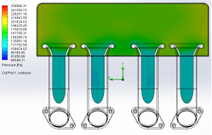
Fig. 9.
Visualization of pressure decomposition |
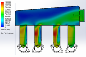
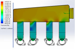
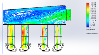
Fig. 10.
Movement of the parts inside the manifold
The study was conducted using the
Flow Simulation Solid Works 2014 package (academic version). The set pressure
corresponded to the current inlet pressure of the engine or a 1.0 bar at the
manifold outlet (inlet to the cylinder) when the simulation of atmospheric
pressure prevailed.
|
|
|
|
|
Fig. 11.
Visualization of the parts’ flow velocity |
Fig. 12.
Visualization of pressure decomposition |
|
Figures 11-13 show the results of the
flow simulation for the second version of the engine intake manifold.
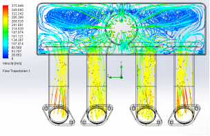
Fig. 13.
Movement of the parts inside the manifold
A visible improvement in the second
version of the inlet manifold provided a uniform distribution factor for each
cylinder of the engine. In addition, there was an improvement in the uniformity
of pressure distribution throughout the volume of the manifold.
5.
RESEARCH RESULTS AND DISCUSSION
The simulations allowed us to
determine the maximum flow rate factor for both versions of the intake
manifold. Figure 14 shows the results of the maximum flow velocity for each
cylinder.
|
|
|
||
|
b) |
|
||
|
Fig. 14.
Maximum flow velocity for the manifold: a) Version I and b) Version II |
|||
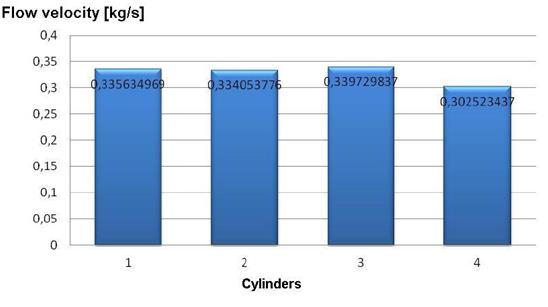
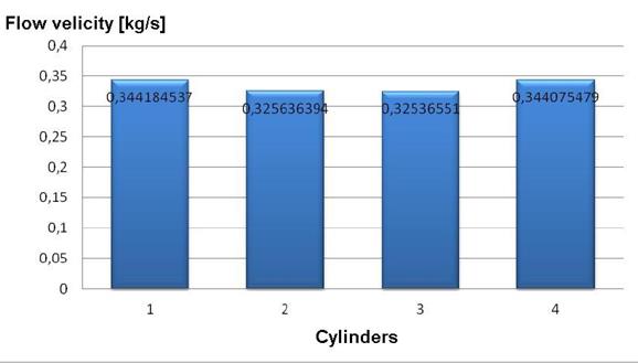
An improvement in the velocity distribution in
each runner is visible, while the maximum value of flow velocity can be more
clearly observed. The improvement in the medium flow through the intake
manifold in turn improves the filling factor, while increasing the output
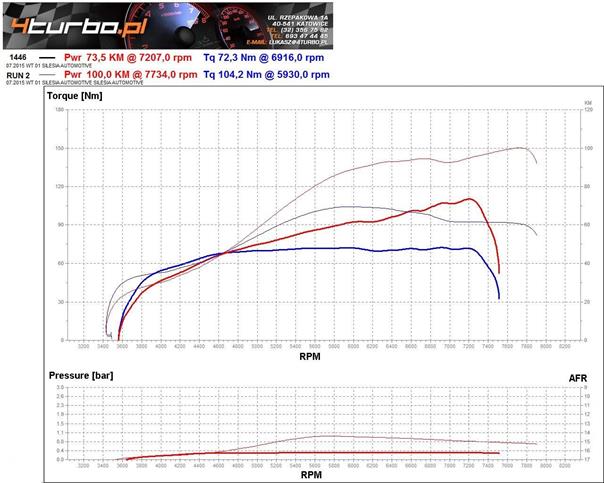
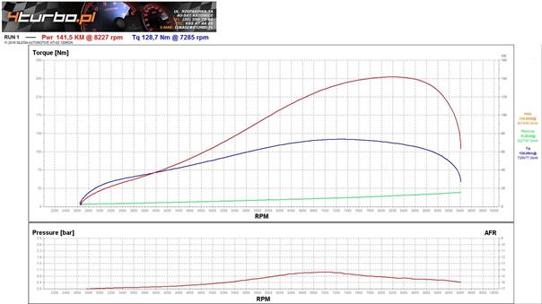
parameters of the engine. Figure 15 shows the external characteristics of the
engine manifold used in Versions I and II.
The maximum torque and maximum power are shown
in Table 1.
Table 1. Comparison
of the engine parameters
|
Parameters |
Inlet manifold Version II |
Inlet manifold Version I |
|
Power [kW/KM] |
103.3/141.5 |
74/100 |
|
Torque [Nm] |
128,7 |
104.2 |
|
Power
RPM [min-1] |
8,227 |
7,734 |
|
Torque
RPM [min-1] |
7,285 |
5,930 |
The measurements obtained using a
chassis dynamometer, as shown in Table 1, confirm the changes in the intake of
the engine, the effect of which is a significant increase in power and torque,
as well as an increase in the dynamics of the vehicle movement.
6.
CONCLUSIONS
Simulation studies were carried out on the bench, with the vehicle
driven by a ZI engine, in order to make design changes to the intake system,
evaluate the influence of the intake manifold’s structure on the performance of
the vehicle and engine, and observe changes in the flow of refrigerant through
the intake manifold. The research produced the following conclusions:
1. Introducing the central inlet
manifold caused an alignment of factors discussed in the chapter among
individual channels (runners). This resulted in a uniform operation of the
engine in terms of idle speed.
2. The use of bell-shaped inlets, also
known as “trumpets”, increased the flow rate through the intake manifold. A 3%
increase in the flow velocity was registered in relation to the collector-free
trumpets and the inlet side refrigerant.
3.
Changing
the structure of the intake manifold can result in an increase in power and torque.
Engine power increased by 39% and torque by 23.5%.
It seems reasonable, therefore, to continue research on the optimization
settings of the engine and reducing the resistance of the flow through the
intake system.
a) |
|
|
|
b) |
|
|
|
Fig. 15. Maximum power and torque charts for the manifold: a) Version
I and b) Version II |
References
1.
Systems.
Cambridge: Robert Bentley, Inc.
2.
Bell A. Graham. 2002. Forced Induction Performance Tuning: A Practical Guide to Supercharging
and Turbocharging. Sparkford: Haynes Publishing.
3.
Kordziński Czesław, Środulski Tadeusz. 1968. Inlet Systems of Combustion Engines.
Warsaw: Publishing Communications and Associations.
4.
Luft
Sławomir. 2003. Fundamentals of Engine Construction. Warsaw: Wydawnictwa Komunikacji i
Łączności. ISBN: 9788320618068.
5.
Mysłowski Janusz. 2006. Engines Charging.
Warsaw: Publishing Communications and Associations. ISBN: 978-83-206-1964-5.
6.
Zając Piotr.
2009. Car Engines. Warsaw: Publishing
Communications and Associations. ISBN: 978-83-206-1735-1.
7.
Zając
Piotr. 2010. Car Engines:
Fuelling, Cooling, Oiling, Inlet and Exhaust Systems. Warsaw: Publishing Communications and Associations. ISBN: 978-83-206-1783-2.
8.
Zając Piotr, Leon Maria Kołodziejczyk. 2001. Combustion Engines. Warsaw: School and
Pedagogical Publishing House. ISBN: 9788302079870.
9.
Blair Gordon, Melvin Cahoon. 2006. Race Engine Technology Magazine. Simon
Moss Publishing, September, p. 36-41.
Received 14.11.2016;
accepted in revised form 15.01.2017
![]()
Scientific Journal of Silesian University of
Technology. Series Transport is licensed under a Creative Commons
Attribution 4.0 International License