Article citation information:
Łebkowski, A. Light electric vehicle powertrain analysis. Scientific Journal of Silesian University of
Technology. Series Transport. 2017,
94, 123-137. ISSN: 0209-3324. DOI: https://doi.org/10.20858/sjsutst.2017.94.12.
Andrzej ŁEBKOWSKI[1]
Light Electric Vehicle Powertrain Analysis
Summary.
This paper describes the structure of a light electric vehicle known as the Mia
Electric vehicle. The vehicle parameters and exploitation properties are
presented, while the advantages and disadvantages of the vehicle’s technical
solutions are discussed, along with possible ideas for their improvement.
Vehicle test results on a roller dyno and under actual driving conditions are
presented. The data recorded during tests form the basis of an analysis of the
vehicle powertrain, whose findings are described in the summary along with
testing conclusions.
Keywords: light electric vehicle, EV, BEV,
electric powertrain
1. INTRODUCTION
The properties of electric powertrain systems
make them a popular choice among car designers to power their creations. At the
same time, the thriving era of the large framed cars of the 1970s and 1980s,
together with the widespread use of internal combustion engines, is definitely
coming to an end. With the advent of modern electric powertrains, a new chapter
has begun for automotive technology. Decreasing the mass of a vehicle reduces
the amount of energy required to propel it, as well as allows its body to be
smaller and lighter. The general aim is to optimize the car construction, while
preserving the greatest level of protection for vehicle occupants and other
traffic participants. These efforts are augmented by various systems of machine
vision and remote vehicle detection [1-6], or autonomous driving systems using
data from precise GPS receivers, LIDAR systems or camera clusters installed in
the vehicle [7-12]. Novel construction materials are being engineered,
such as aluminium alloys, carbon fibre-reinforced composites and new plastics.
These tendencies are present both in conventional cars and in electric or
hybrid cars, which exist not because of some short-lived fashion, but because
they stem from the necessity to comply with new and increasingly restrictive legislation on permissible
vehicle fuel consumption amounts and emission limits [13].
Recently, various models designed in this
manner have appeared on the market. One such design was for a vehicle whose
production was stopped after 30 months. It was named the Mia Electric (Fig. 1)
and is the topic of this article, along with some discussion on possible
modifications to it, which could improve its operational adaptability to the
northern regions of Europe.
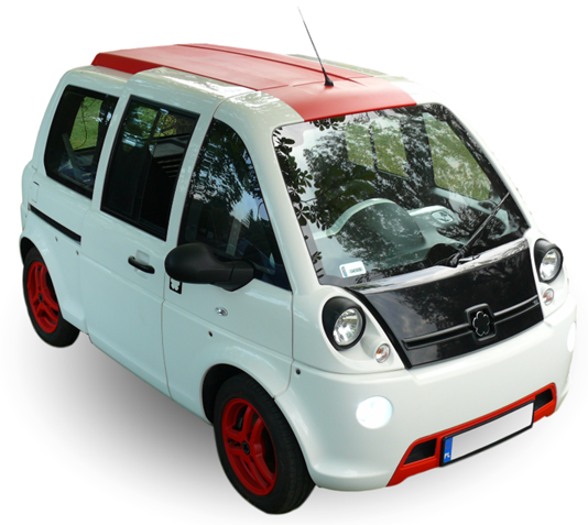
Fig. 1. Mia Electric vehicle
The Mia Electrical vehicle is an example of a futuristic design and
worthy of further inspiration, due to its applied engineering. The vehicle
parameters make it agile, very ecological and economic, with a unit that is
capable of dynamic negotiating with urban areas. The performed tests on the Mia
Electric showed that, while it is not without flaws, these can be rectified
using simple means. Depending on the selected option, the car’s interior can be
upholstered with plastic panels and textile fabric or with leather. The view of
an example interior is shown in Figure 2.
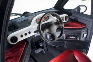
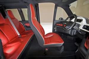
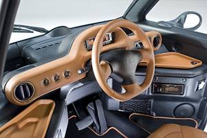
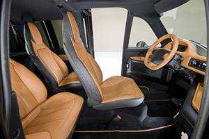
Fig. 2. Mia Electric interior view [15, 16]
The vehicle construction represents an example of how to design an urban
electric vehicle. According to the automotive experts from Carbase [14], by the
end of 2014, the Mia Electric was classified as the third (out of 10) best
electric vehicle in the world, after the Tesla Model S and the BMW i3. The Mia
Electric was regarded as being better overall than other vehicles, such as the
Nissan Leaf, the Renault Twizy and Zoe, the Mercedes B-Class Electric Drive,
the Smart Fortwo, the Tesla Model X and the Volkswagen e-Golf.
2. BASIC PARAMETERS
Mia vehicles were built in France
from June 2011 to December 2013, as typical small urban electric vehicles.
There were three body types produced (Fig. 3): the regular Mia (short
wheelbase, passenger type, three seats), the Mia U (cargo type or “fourgon”,
long wheelbase, one or two seats), the Mia L (passenger type, long wheelbase, 3
or 4 seats), and the luxury Mia Paris [15-17]. A total of about 1,950 vehicles
was produced at an average rate of 65 units per month.
The Mia Electric vehicle consists of
a rigid, light metal structure onto which ABS panels have been glued, forming
sides, fenders, bumpers and a roof. Glass panels forming fixed vehicle windows
have also been glued directly onto the metal structure (Fig. 4).
On both sides of the vehicle, there
are sliding doors with large cutouts in the roof and floor panels, which allow
the driver and occupants to freely board and leave, as well as facilitate
unobstructed loading and unloading.
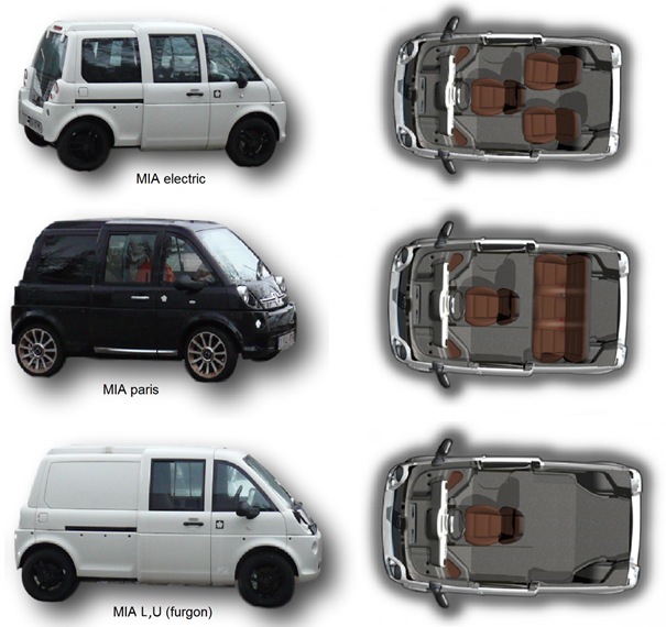
Fig. 3. The tested Mia Electric
vehicles
The driver’s seat is located
centrally on the main axis of the car, which gives the driver a panoramic view
of the vehicle’s surroundings. Such a layout not only enhances the vehicle’s mobility
due to an even mass arrangement, but also allows for the use of less precious
parking space because, with a centrally placed seat and sliding doors, ingress
and egress is possible with minimal spacing in relation to surrounding objects
(e.g., parked cars) on the vehicle’s sides. The potential for the driver to
enter the vehicle from either side also facilitates parking in confined spaces.
Behind the driver’s seat, depending on the vehicle option, there is cargo space
(in the “fourgon” model U), or two single seats (in the Mia, Paris and L
models), or one couch with three seats (the L “banquette” model). A
particularly ergonomic version of the Mia is one with three seats, i.e., with a
central driver’s seat and two passenger seats in the rear, where there is
generous legroom available to passengers on both sides of driver’s seat. The
rear of the vehicle contains a tempered glass trunk door, which can be opened
by pressing on the key fob or a button on the dashboard.
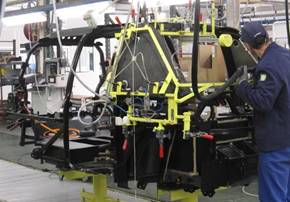
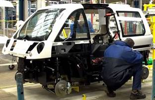
Fig. 4. The metal structure of the
Mia Electric vehicle [17]
The electric powertrain of the
vehicle is placed in the rear and consists of an induction motor, powered by a
bank of lithium-iron-phosphate (LiFePO4) batteries through an inverter (Fig.
5). The whole powertrain is shielded by an aluminium cowling, shaped in order
to direct the airflow around the moving car, which cools the motor and the
inverter.
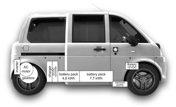
Fig. 5. View of the powertrain from the bottom
of the vehicle
On-board auxiliary devices, such as
external lights, windscreen wipers, a cabin blower and an electric power
braking vacuum pump, are powered from a standard 12 V vehicle supply, which
contains a buffer battery with a 17 Ah capacity that is supplied by two
parallel DC/DC converters (600 W each) from the high-voltage traction battery.
Internal devices communicate with each other using a CAN bus.
The main power source (traction batteries) use LiFePO4 cell chemistry
and is divided into two battery packs, located centrally in special
compartments at the bottom of the body. Each pack is bolted on top of aluminium
panels, which are subsequently bolted to the bottom of the vehicle body. The
larger of the battery packs, weighing 92 kg, has a nominal voltage of 48 V,
contains 7.7 kWh of power and is installed individually in the front battery
compartment located directly under the driver’s seat. The smaller battery pack,
weighing 55 kg, has a nominal voltage of 28.8 V, contains 4.6 kWh of power and
is installed on the aluminium panel, together with two DC/DC converters and the
charger, which sits over the converters on a sheet metal riser (Fig. 6). The
set consisting of the smaller battery pack, the charger and the DC/DC
converters is installed in the rear battery compartment.
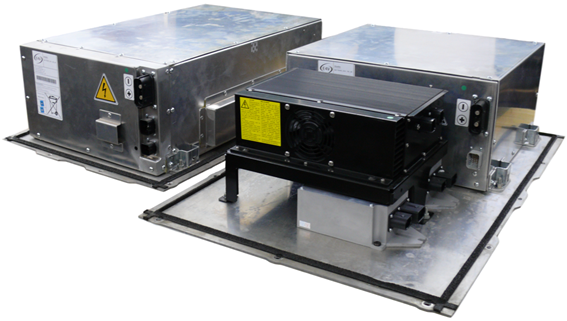
Fig. 6. View of the battery packs, the charger
and the DC/DC converters
The LiFePO4 battery was built by E4V from 25 cell blocks with a 160 Ah
capacity. Each cell block consists of four individual constituent cells, which
have a capacity of 40 Ah each. The parameters of each battery block are
monitored by a battery management system (BMS) system, also built by E4V. The
view of one battery pack with a BMS system is shown in Figure 7.
The BMS system built by E4V belongs to a group of active systems, which
use resistor loads to balance the voltage levels on the battery blocks. During
charging, when a given block reaches the set voltage, the BMS uses a relay to
connect, in parallel, a resistor to that block in order to bypass the majority
of charging currents from that block. When all the blocks of a battery reach
the set voltage, the BMS sends a command to the charger ordering it to stop
charging. Unfortunately, the company that designed the BMS made some design
errors, such that, during the life of
the vehicle, it is possible that its 12 V auxiliary battery could become
completely discharged if the vehicle were to be left unused for a long time.
The vehicle designers probably did not foresee the standby charging mode of 12
V from the main traction batteries, when the 12 V battery level becomes low.
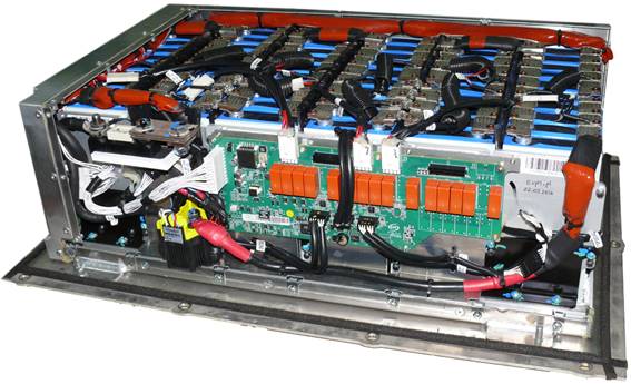
Fig. 7. View of the LiFePO4 battery pack with
the BMS board
Furthermore, after a prolonged
standstill, the internal BMS components of both battery packs enter a kind of
lockdown mode, which puts the vehicle out of commission. Lifting the lockdown
is only possible after a costly service. There is, however, an alternative in
the form of a firmware modification, performed by direct connection to the CPU
of the BMS and by applying the changes to the program memory (Fig. 8).
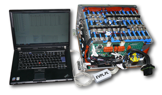
Fig. 8. BMS software modification of a LiFePO4
battery pack
Another
obstacle that a user may face during the operation of Mia vehicles is the inability to discharge or
charge the batteries when their temperature drops below 0°C. In such a
scenario, after turning on the ignition, an indicator lights up on the
dashboard informing the driver that the battery system is disabled due to low
temperature. The charging is inhibited in the same way: after plugging in the
charging cord, the charging will not commence.
The main
element of the powertrain is the air-cooled induction motor with a continuous
power of 10 kW, weighing 35 kg. It is sourced from Leroy-Somer (a producer of
electric motors since 1919 and a supplier of powertrains for Peugeot and
Citroën). The motor can be briefly overloaded up to 18 kW, while the maximum
motor speed is 9,600 RPM. The IP54 level of protection from water splashes
allows for the installation of the motor under the trunk floor, behind the rear
fender, as shown in Figure 9.
The torque
generated by the motor is transmitted through a single-speed gearbox with a
differential to two drive shafts connected to rear wheels [18]. Braking is
performed by disc brakes on the front axle and drum brakes in the rear axle,
while the braking system is supported by an ABS and an active brake assist
(ABA) system. Additionally, the properties of the inverter allow the vehicle to
activate regenerative braking at 10% maximum drive torque and a maximum
regeneration battery current of 160 A, provided the acceleration pedal is let
off, which simulates the response of the conventional drive, but with the
advantage of recovering a part of the vehicle’s kinetic energy by putting the
motor into generator mode and charging the battery as the vehicle brakes.
Regenerative braking will not be available when the battery’s state of charge
exceeds 90% or the battery temperature is close to 0°C.
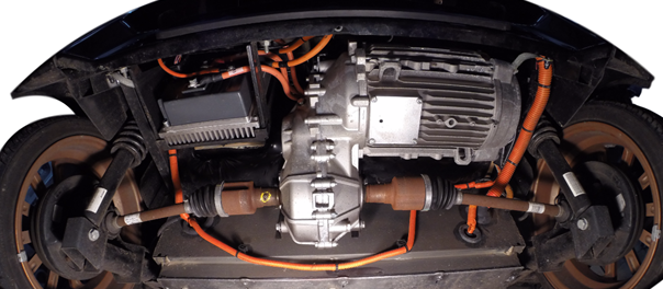
Fig.
9. View of the bottom of the vehicle, with visible powertrain components
The control of the traction motor is
performed by the Gen4 Size 4 inverter built by Sevcon. Sevcon inverters are
characterized by their compact construction, while retaining the ability to
control large powered motors. The Sevcon Gen4 Size 4 inverter, which conforms
to the 89/336/EEC Electromagnetic Compatibility Directive, has a mass of 2.7
kg, operating voltage limits from 50.4 to 96 V, a rated continuous RMS current
of 140 A and a two-minute rating of 350 A. This means that the inverter is
capable of controlling power of about 30 kW. The motor’s rotor position is
acquired with an incremental encoder with AB output. The inverter uses the
field-oriented control algorithm, which allows independent control of motor
flux and torque. In order to fully configure the inverter to operate with a
given motor, it is required to set about 280 various parameters, starting with
basic motor parameters and finishing with inverter input/output definitions.
The inverter allows for configuring selectable drive profiles; the Mia uses two
such profiles, namely, regular and ECO. The ECO profile limits the maximum
power output, especially during vehicle starting and acceleration.
Table 1. The parameters of the Mia Electric vehicle [15-17]
|
Index |
Name |
Data |
Unit |
|
Dimensions (Mia, Paris) |
2,870 x 1,640 x 1,550 |
(mm) |
|
|
2 |
Dimensions (L, U) |
3,190 x 1,640 x 1,550 |
(mm) |
|
3 |
Wheelbase |
1,960 |
(mm) |
|
4 |
Turning radius |
4.3 |
(m) |
|
Number of seats |
1 ÷ 4 |
(pcs) |
|
|
6 |
Battery type |
LiFePO4 |
- |
|
7 |
Nominal voltage |
76.8 |
(V) |
|
8 |
Battery energy total |
8 or 12.3 |
(kWh) |
|
9 |
Battery mass |
95 or 145 |
(kg) |
|
10 |
Charger type |
iSSynergy ELIPS HF65-95V 40A |
|
|
11 |
Approx. battery charging time |
3 or 5 |
(h) |
|
On-board charger power |
2.4 |
(kW) |
|
|
13 |
DC/DC converter power |
2 x 0.6 |
(kW) |
|
14 |
Curb weight depending on battery
model and capacity |
764 ÷ 850 |
(kg) |
|
Gross vehicle weight rating depending on battery model |
1,160 ÷ 1,200 |
(kg) |
|
|
Motor type |
Asynchronous |
||
|
17 |
Motor power |
10 |
(kW) |
|
18 |
Motor peak power |
18 |
(kW) |
|
19 |
Motor torque |
58 (peak 65) |
(Nm) |
|
20 |
Gearbox |
Single speed |
|
|
21 |
Gearbox ratio |
8.4 : 1 |
|
|
22 |
Inverter |
SEVCON Gen4 Size4 |
|
|
Cooling fan (430 m3/h) |
45 |
(W) |
|
|
24 |
Cabin heating power |
0.75 |
(kW) |
|
25 |
De-icing system power |
1.5 |
(kW) |
|
26 |
Body structure |
Cold-rolled steel closed sections
and steel sheet joined by welding |
|
|
Body skin |
ABS |
||
|
28 |
Vehicle range at 15 ÷ 20°C (NEDC) |
80 or 125 |
(km) |
|
29 |
Top speed |
100 |
(km/h) |
|
30 |
Specific energy consumption |
96 |
(Wh/km) |
|
31 |
Braking system aids |
ABS, ABA system |
|
|
32 |
Recycling ratio |
95 |
(%) |
An
example configuration of motor flux and torque is presented in Figure 10.
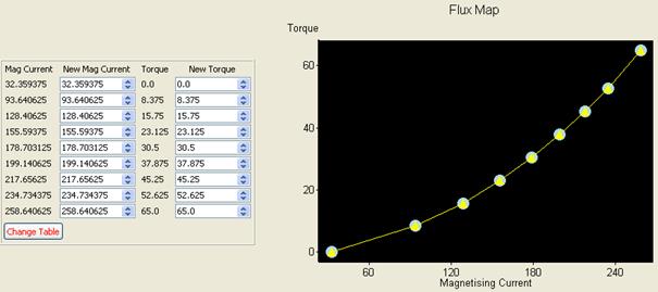
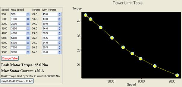
Fig. 10. Inverter configuration of motor flux
and torque maps
3. TESTING THE ELECTRIC POWERTRAIN
The
electric powertrain tests were conducted under real driving conditions and on a
roller dyno. Three Mia vehicles were tested: the regular Mia, the Mia U and the Mia Paris. The
test data were recorded with an electric vehicle data recorder [19]. The
example data plots recorded during the tests are presented in Figures 11 and
12.
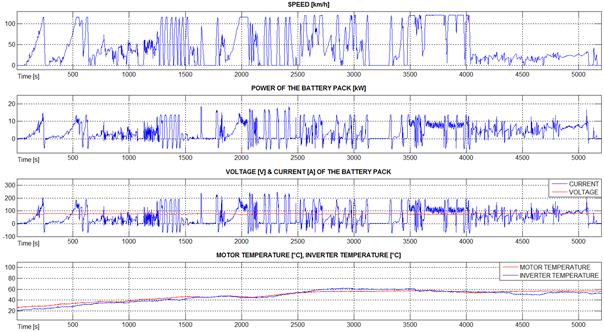
Fig. 11. Plot of example data recorded during
the dyno tests of the Mia Electric vehicle
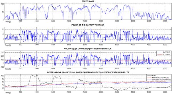
Fig. 12. Plot of example data recorded during
the road tests of the Mia Electric vehicle
4. ANALYSIS OF THE RESULTS
During the testing on a roller dyno,
the power and torque generated by the powertrain were analysed in relation to
the flux map and the power limit table. As aerodynamic drag was not present,
the vehicle reached a top speed of 120 km/h, which corresponds to a motor
rotation speed in the order of 9,570 RPM. Exceeding the 9,600 RPM mark would
have triggered the overspeed fault and stopped the drive. Changing the settings
of power and torque to above 110% of the factory settings value caused
excessive temperature rises in both the motor and the inverter.
Testing under road conditions
corroborated the very low powertrain energy consumption claims. The measured
energy consumption per km in a mixed cycle (urban/extra-urban driving) and at
an average ambient temperature of 25°C was 90 Wh/km (compared to the factory
claim of 96 Wh/km). Still, the result was achieved in active ECO mode, with an
average velocity of 54 km/h at a distance of 120 km (with a maximum top speed
of 81 km/h).
Had the ECO mode been inactive, the
energy consumption would have been higher because of the faster acceleration of
the vehicle. The electric powertrain parameters are sufficient, while the
vehicle is not a traffic nuisance; rather, it is quite agile and effortlessly
reaches speeds of over 90 km/h, which is the result of a programmed power limit
map, where the torque decreases in line with increasing speed.
The top speed achieved during the
testing was 102 km/h. The central driver’s position in the Mia Electric vehicle
is similar to that in a sports car, which can encourage a “sporty” driving
style. In this case, the energy consumption can double, increasing even up to
180 Wh/km.
The vehicle operation changes
completely during colder seasons. The capacity of the employed LiFePO4 battery
is reduced by 8% for each 10°C drop in temperature from the reference value of
20°C [20]. Additionally, the manufacturer did not engineer any thermal
conditioning means. In turn, as the battery temperature reaches 0°C, the
vehicle battery will neither charge nor discharge rendering the vehicle as
useless. During the testing, one of the vehicles was fitted with a custom
battery thermal conditioning (heating) system, which eliminated all the
problems resulting from a low battery temperature.
The possibility of modifying the
unhindered inverter parameters makes the presented energy consumption figures
variable, but their values are a direct consequence of driving style (sporty or
economic).
The ratio of energy recovered during
regenerative braking to energy consumed was about 7.5% (with a setting of 10%
braking torque in relation to drive torque). The vehicle is very sensitive to
driving style, as well as road conditions (urban or extra-urban).
The test also confirmed the high
efficiency of the powertrain, which uses only air cooling. During the tests,
temperature rises of no more than 40°C were observed. It is worth noting that
the applied motor does not contain any neodymium permanent magnets, which, when
subjected to high temperature and high currents, can demagnetize. The maximum
power consumption observed during the tests never exceeded 23 kW.
In the tested vehicle, the factory
settings of the inverter were correctly chosen, albeit with a slight reserve,
which could be utilized with a small change in the settings. The introduced
modifications to the BMS firmware, along with installation of a battery thermal
conditioning system, have greatly increased the efficacy of the vehicle under
low ambient temperature conditions.
5. CONCLUSIONS
Light electric vehicles represent an
alternative direction in transport development, especially in larger cities.
They use less space, consume a little energy, do not pollute the air and emit
almost no noise.
The application of an electric
powertrain allows for a reduction in the energy consumption spent on motion to
about 100Wh/km in relation to about 350-400Wh/km expended by comparatively
sized conventional cars, equating to a consumption of 3-4 l of conventional
gasoline or fuel oil.
The decreased energy consumption
means decreased costs of operating these electric vehicles, not to mention the
lack of regular costs for oil changes or replacing various worn engine
components.
With the application of two-way
battery chargers, a power flow control and a monitoring system, the presence of
a large number of capable electric vehicles should enable the creation of a
smart grid with vehicles’ batteries acting as a buffer to mitigate the power
fluctuations located in the electric grid.
Electric vehicles can substantially
reduce the local emission of noxious gasses into the environment, since they
emit no exhaust and use no oxygen; their operation is almost neutral to the
surrounding environment. In addition, they have a high recycling level (95% in
the case of Mia) and emit less noise, especially at velocities of less than 60
km/h, which in turn positively impacts on the general population’s health [20-22].
Meanwhile, they generate less vibration than conventional vehicles [23-30].
References
1.
Lange Stefan,
Ulbrich Fritz, Daniel Goehring. 2016. “Online vehicle detection using deep
neural networks and lidar based preselected image patches.” IEEE Intelligent Vehicles Symposium.
DOI: http://doi.org/10.1109/IVS.2016.7535503.
2.
Chuanrong Li, Mei
Zhou, Liu Menghua, Ma Lian, Wang Jinhu. 2016. “A concealed car extraction
method based on full-waveform LiDAR data”. Mobile
Information Systems. DOI: http://doi.org/10.1155/2016/3854217.
3.
Yansong Liu,
Sildomar T. Monteiro, Eli Saber. 2016. “Vehicle detection from aerial color
imagery and airborne LiDAR data.” IEEE
International Geoscience and Remote Sensing Symposium (IGARSS). DOI: http://doi.org/10.1109/IGARSS.2016.7729354.
4.
Michael Kusenbach,
Michael Himmelsbach, Hans-Joachim Wuensche. 2016. “A new geometric 3D LiDAR
feature for model creation and classification of moving objects.” IEEE Intelligent Vehicles Symposium.
DOI: http://doi.org/10.1109/IVS.2016.7535397.
5.
Kenneth Schofield,
Mark L. Larson, Keith J. Vadas. 1999. “Display enhancements for vehicle vision
system”. US Patent US5949331A.
6.
O'Cualain Diarmad,
Martin Glavin, Edward Jones. 2016. “Method for detecting an object in an
environmental region of a motor vehicle by means of a camera system of the
motor vehicle, camera system and motor vehicle.” US Patent US9340156B2.
7.
Rosolia Ugo, Stijn
De Bruyne, Andrew G. Alleyne. 2016. “Autonomous vehicle control: a nonconvex
approach for obstacle avoidance.” IEEE
Transactions on Control Systems Technology, Vol. PP, Iss. 99.
8.
Boyuan Li, Du
Haiping, Li Weihua. 2015. “Trajectory control for autonomous electric vehicles
with in-wheel motors based on a dynamics model approach.” IET Intelligent Transport Systems, Vol. 10, Iss. 5: 318-330. DOI:
http://doi.org/10.1049/iet-its.2015.0159.
9.
Xiaozhi Chen, Kaustav Kundu, Yukun Zhu, Huimin Ma, Sanja Fidler, Raquel
Urtasun. 2016. “3D object proposals using stereo imagery for
accurate object class detection.” Computer Vision and Pattern Recognition. arXiv:1608.07711.
10.
Mutz Filipe, Lucas P. Veronese, Thiago Oliveira-Santos, Edilson de
Aguiar, Fernando A. Auat Cheein, Alberto Ferreira De Souza. 2016. “Large-scale mapping in complex field scenarios using an autonomous car.” Expert Systems with Applications,
Vol. 46: 439-462.
11.
Ingle Shantanu, Madhuri Phute. 2016. “Tesla autopilot: semi autonomous
driving, an uptick for future autonomy.” International
Research Journal of Engineering and Technology, Vol. 3, Iss. 9.
12.
Le Vinea Scott, Alireza Zolfaghari, John Polak. 2015. “Autonomous cars:
the tension between occupant experience and intersection capacity”. Transportation Research Part C: Emerging
Technologies, Vol. 52.
13.
“Reduction of pollutant emissions from light vehicles.” 2016. Available
at: http://eur-lex.europa.eu.
14.
“10 of the best electric vehicles”. 2016. Available at: http://www.carbase.co.uk.
15.
“Mia, the ideal electric car designed for the city.” 2016. Available at:
mia-automobile-club.com.
16.
“Mia electric micro.bus”. 2016. Available at: http://www.greencardesign.com.
17.
“Mia electric innove pour mieux rebondir”. 2016. Available at: http://www.largus.fr.
18.
Łebkowski Andrzej. 2017. “Electric vehicle data recorder”. Przegląd Elektrotechniczny, Vol. 2. ISSN 0033-2097. Doi:
http://doi.org/10.15199/48.2017.02.62.
19.
Łebkowski Andrzej. 2016. “Temperature, overcharge and short-circuit
studies of batteries used in electric vehicles”. Przegląd Elektrotechniczny. ISSN 0033-2097. (In print).
20.
Figlus Tomasz, Jozef Gnap, Tomas Skrucany, Branislav Sarkan, Jozef Stoklosa.
2016. “The Use of Denoising and Analysis of the Acoustic Signal Entropy in
Diagnosing Engine Valve Clearance”. Entropy,
Vol. 18, Issue 7: 1-11.
DOI: http://doi.org/10.3390/e18070253. ISSN: 1099-4300.
21.
Kotak B., Y. Kotak. 2016. “Review of European Regulations and Germany's
Action to Reduce Automotive Sector Emissions”. European Transport\Trasporti Europei, Issue 61, Paper no 7:
1-19. ISSN: ISSN 1825-3997.
22.
Łebkowski Andrzej. 2015. “Emission of noise in electric vehicles”. Economics and Organization of Enterprise,
No.7: 48-62. ISSN 0860-6846.
23.
Bensana
T., S. Mekhilef. 2016. “Numerical and experimental analysis of vibratory
signals for rolling bearing fault diagnosis”. Mechanika, Vol. 22, No 3: 217-224. DOI: http://dx.doi.org/10.5755/j01.mech.22.3.11962.
ISSN: 1392-1207.
24.
Czech Piotr, Grzegorz Wojnar, Rafał Burdzik, Łukasz Konieczny, Jan Warczek.
2014. “Application of the discrete wavelet transform and probabilistic neural
networks in IC engine fault diagnostics”. Journal
of Vibroengineering, Vol. 16, Issue 4: 1619-1639. ISSN 1392-8716.
25.
Czech Piotr. 2012. “Identification of leakages in the
inlet system of an internal combustion engine with the use of Wigner-Ville transform
and RBF neural networks”. In Jerzy Mikulski (ed.). 12th International
Conference on Transport Systems Telematics. Katowice Ustron, Poland. 10-13
October 2012. Telematics in the Transport Environment. Book Series: Communications in Computer and Information
Science, Vol. 329: 414-422.
26.
Czech Piotr. 2013. “Intelligent approach to valve
clearance diagnostic in cars”. In Bronius Baksys, Algirdas Bargelis,
Stasys Bockus, Algimantas Fedaravicius, Vylius Leonavicius, Pranas Ziliukas,
Romualdas Dundulis, Tilmute Pilkaite (eds.). Proceedings of the18th
International Conference on Mechanika. Kaunas University of Technology, Kaunas,
Lithuania. 4-5 April 2013. Kaunas University of Technology. Book Series: Mechanika Kaunas University of Technology:
58-61.
27.
Louahem
M‘sabah H., A. Bouzaouit. 2016. “Degradation model of the bearings by wiener
process”. Mechanika, Vol. 22, No 3:
225-228. DOI: http://dx.doi.org/10.5755/j01.mech.22.3.13000. ISSN: 1392-1207.
28.
Madej
Henryk, Piotr Czech. 2010. “Discrete wavelet transform and probabilistic neural
network in IC engine fault diagnosis”. Eksploatacja
i Niezawodnosc - Maintenance and Reliability, Vol. 4(48): 47-54. ISSN:
1507-2711.
29.
Obuchowski
Jakub, Radoslaw Zimroz, Agnieszka Wylomanska. 2016.
“Blind equalization using combined skewness-kurtosis criterion for gearbox
vibration enhancement”. Measurement,
Vol. 88: 34-44.
DOI: http://doi.org/10.1016/j.measurement.2016.03.034. ISSN: 0263-2241.
30.
Wodecki
Jacek, Pawel Stefaniak, Jakub Obuchowski, Agnieszka Wylomanska, Radosław Zimroz.
2016. “Combination of principal component analysis and time-frequency
representations of multichannel vibration data for gearbox fault detection”. Journal of Vibroengineering, Vol. 18,
Issue 4: 2167-2175.
DOI: 10.21595/jve.2016.17114. ISSN: 1392-8716.
Received 04.01.2017;
accepted in revised form 20.02.2017
![]()
Scientific Journal of Silesian University of
Technology. Series Transport is licensed under a Creative Commons
Attribution 4.0 International License