Article citation information:
Buchalik, R. Evaluation of a conceptual vehicle steering system for
independent wheel control. Scientific
Journal of Silesian University of Technology. Series Transport. 2017, 94,
19-26. ISSN: 0209-3324. DOI: https://doi.org/10.20858/sjsutst.2017.94.2.
Ryszard BUCHALIK[1]
EVALUATION
OF A CONCEPTUAL VEHICLE STEERING SYSTEM FOR INDEPENDENT WHEEL CONTROL
Summary.
This paper presents a brief description of an unconventional steering system
involving electronic stability control and its influence on vehicle motion. The
proposed configuration enables individual changes in steering angle for each
single wheel, in contrast to the mechanical linkage solution. An analysis of
vehicle behaviour during emergency braking on a heterogeneous surface is
conducted, especially with regard to the undesirable rotation of the vehicle
body. The benefits of using this active steering system, implemented in the
steer-by-wire mode, are characterized, while the problems for further
consideration and the potential benefits of such a solution are described.
Keywords:
steer-by-wire, drive-by-wire, Ackermann geometry, independent four-wheel
steering, toe angle, vehicle steering, cornering control
1. INTRODUCTION
The number of vehicles used across
the world is constantly growing at a very fast rate. This causes several
complications related to safety, infrastructure, environmental pollution,
financial cost (purchasing, operating, recycling), social and medical problems.
One of the most important issues is the active safety of a car. This area of
research is still in the phase of intensive development among automotive
manufacturers, given that customers constantly replace their vehicles in search
of more state-of-the-art requirements.
2. ACTIVE STEERING SYSTEMS
One of the most significant aspects
of active safety involves the design of the steering system, which has
undergone significant changes in recent decades. Among the changes has been
power steering, which is commonly used nowadays. It allows less restricted
adaptation of wheel geometry, self-aligning torque, tyre width (friction during
rotation at standstill) and steering ratio over an entire or partial range.
Some systems are able to facilitate self-manoeuvring (e.g., Autonomous Park
Assist). Another implemented solution, albeit much less common today, is the
possibility of linking the steering wheel with the rear axle, which can be done
in a passive way. For example, the angle of the axis of rotation (connection to
the structure) of the rear wheel’s control arm can be designed in such a way
that, when the forces resulting from the cornering occur (load down at the
vehicle’s external side, centrifugal force), the angle of the wheel remains
appropriate. This solution is widely used in many commercial cars [6]. For the
Porsche 928, a solution called the Weissach axle was used to control the angle
of the wheel during cornering and decelerating in order to create a lateral
force on the rear axle. Through such operations, an understeer gradient can be
shaped in some situations. Obvious examples of passive steering are a trailer
and an articulated bus. That said, in this paper, the focus is on vehicles with
two axles. Currently, some systems available on the market are able to actively
control the rear axis wheel’s steering angle in a comparable way to that for
the front wheels, e.g., those of Renault 4Control (Talisman, Laguna), Delphi
Quadrasteer (Chevrolet Silverado) and Nissan HICAS, as well as solutions
designed by Toyota and Honda. Typically, the actuator facilitates power
steering in the front axis either electrically through a rack and pinion or
hydraulically. At low speeds, for example, during a parking manoeuvre, the
front and rear wheels twist in opposite directions. This reduces the turning radius
of the vehicle and, most importantly, the necessary space in which to make a
turn. While driving at higher speeds, all the wheels twist in the same
direction, which improves overall stability because the car does not rotate so
intensively around its vertical axis. The advantages of the active system,
compared to the passive one, are as follows: a wider range of possible steering
angles of the wheel, the possibility of adjusting the direction, and the value
of turning to the current undesirable kind of slip (understeer or oversteer,
specified by the electronic traction control and its work characteristics). The
tendency to understeer or oversteer is varied due to factors that cannot be
foreseen at the design stage, such as the state and geometry of the road
surface, the characteristics of the tyres, the distribution and value of the
vehicle load, the longitudinal force of each tyre (braking or accelerating),
cornering and the dynamic state of the whole vehicle body, and the unsprung
mass. Another possible steering modification is when the steering angle of the
front wheels, resulting from the current angle of rotation of the steering
wheel (rudder), adds or subtracts a certain value by summing the planetary
gear. This can be used to implement the variable steering gear ratio depending
on driving conditions and driver preferences and based on the data collected by
the electronic stability control and a special algorithm, e.g., BMW Active
Steering.
A crucial
issue is the shape of steering linkage geometry, which binds the rotation angle
of one wheel (relative to the pivot angle) with an equivalent angle of the
second wheel on the same axle. The starting point for further consideration is
Ackermann geometry, which ensures the correct kinematics of the wheel, i.e.,
lines that are perpendicular to the free rolling direction of all four wheels
(on the ground/road plane) starting at the points of contact that intersect
with the ground at exactly one point. In fact, there are exceptions from this
principle [7], especially due to a greater downward force on the vehicle’s
outer side during cornering, making it possible for larger centrifugal forces
to transfer. The dependence of the lateral force generated by the tyre, which
(in the absence of other excitations) is mainly the centrifugal one, depends on
the wheel sideslip angle, that is, the difference between the velocity
direction and the direction of free rolling. The maximum value of the lateral
force, which is possible to transfer, increases with the vertical load exerted
by the body of the car (gravity force and accelerations). The steering linkage
geometry should be designed with respect to the above- mentioned issues and
provide the widest possible range of steering angles in order to reduce the
minimum turn radius. Usually, while tight cornering at low speed, kinematic
inconsistency occurs, which results in a higher rolling resistance and
increased tyre wear. The steering linkage geometry is always a compromise
between many different desired characteristics. To find the optimum angle of
each of the two steered wheels, at an arbitrary turning radius, it is necessary
to know, among other things, the mass distribution of the vehicle, the state of
its longitudinal motion (speed, acceleration, deceleration) and the dependence
of the lateral force transmitted by the tyre from the vertical load and
longitudinal force, as well as other characteristics of the suspension, its
kinetics, including elastokinematics, the road profile and surface type. Not
all of them can be predicted at the design stage, so it is proposed to consider
a system that allows for the independent control of the steering angle of the
left and right wheel. Such a solution is possible only in drive-by-wire
architecture by implementing computer-controlled actuators, although physical
connections can be preserved as required by the law [10].
While the literature describes the testing of
prototype transporter robots and cars with a four-wheel swivel [2, 5], as well
as prototypes built by big car manufacturers (Toyota Fine-T, Nissan Pivo), they
mainly move at low speed, with their main advantage being manoeuvrability. The
following discussion focuses on behaviour at high speed under real driving
conditions.
3. EMERGENCY BRAKE WITH ACTIVE STEERING
An example of a situation in which
an active steering system could bring some benefit is the breaking process of a
car on heterogeneous surfaces. Figure 1 shows the top view of a car moving from
left to the right, performing emergency braking. The left-hand side wheels run
on the surface with lower friction coefficient μ1, whereas the right-hand
side wheels run with coefficient μ2. Such a situation may occur during
partial running onto a roadside covered with snow, when the central part of the
road is dry. In the following discussion, a simplified model of the tyre was
used, with the assumption that the sum of the longitudinal and lateral forces
transmitted by the tyre have a constant maximum value, which is represented by
the vector starting at a tyre-surface contact point and ending inside a
delineated circle [4]. The circle radius represents the maximum possible
friction force. In the presented situation, the driver (or autonomous driving
program) attempts to maintain a straight-line trajectory until the vehicle comes
to a complete stop of the vehicle. Each of the four forces depicted in Figure 1
is a source of torque around the gravity centre of the car. The radii of these
moments are all the same, i.e., equal to half of the axis length. However, the
value of forces that tends to turn the vehicle body anticlockwise (FRL
and FFL) is smaller than the corresponding forces at the right-hand
side of the vehicle, which strives to turn it clockwise. As shown, forces
acting on the vehicle cause it to rotate relative to the centre of mass, which
is obviously undesirable. The first method to counteract this is a partial
reduction of the braking force, especially for the more adhesive wheels. This
causes a reduction in the whole body-rotating torque and allows the tyres to
transmit lateral forces, which counteract the rotation. However, in this case
the braking distance is elongated. The presented situation is an important
issue when creating an algorithm for the anti-lock braking system’s (ABS’)
controller. Currently available systems use advanced computational methods in
order to find the optimum configuration [8]; however, there are some general
principles involved. In the case of front wheels, it is desirable to achieve a
maximum braking force. In the case of rear wheels, seeking to reduce the
braking torque on wheels with better traction makes it possible to reduce the
rotating torque and transmit a lateral force with the wheel, whose grip is not
fully utilized in the longitudinal direction. This helps to maintain the car’s
stability.
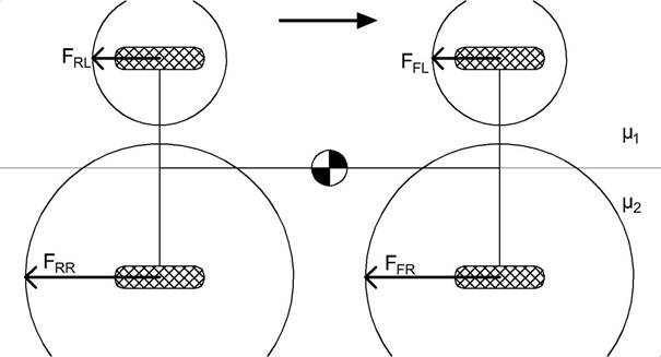
Fig. 1. Braking with a conventional system
Figure 2 shows a possible configuration of wheels in
the same situation as described above, which involves the possibility of
independently adjusted steering angles. In this case, the front-right wheel is
set at an angle, in which the force FFR is generated. It can be
decomposed into the longitudinal component FFR(x), which causes
deceleration, and the FFR(y) component, which counteracts the
rotation relative to the gravity centre of the vehicle body. The first step is
to determine the direction of force FFR and thus the ratio of
longitudinal to lateral forces. This should be done in a way that does not
reduce the deceleration too much, while simultaneously achieving a significant
contribution to the balance of torques in relation to the gravity centre. A
tyre, whose direction of motion is not identical to the free rolling direction
becomes a source of force FT(y). After the direction of force FFR
is designated, a lateral force dependence relative to the angle of sideslip for
the specified tyre type and operation conditions should be used to find this
angle. The camber, castor, scrub radius, forces, kinematics (including
elastokinematics) and other important design features should be taken into
account, as well as their current value and change during the rotation around
the pivot axis. As force FT(x) results mainly from the operation of
the brake system, it should be correctly set, for example, by components of the
ABS and the electronic stability program in order to achieve the maximum
overall wheel reaction. The total force generated by tyre FT is of
course equal to force FFR acting on the vehicle body. A
two-dimensional model was used, while the vertical dynamics related to the
action and kinematics of suspension, were omitted. The next stage of the
development, according to the presented concept, is a system with four-wheel
(as opposed to only two-wheel) independent steering, in which the rear axle can
be used in a similar way. The main advantage of the described solution is a
significant reduction or elimination in the torque, which rotates the car’s
body. Such an effect may also be achieved in other ways. One possibility is an
appropriate driver response, causing the steering wheel to rotate in the correct
direction to counteract the rotation of the vehicle. A second solution involves
the negative scrub radius shown in Figure 3, with the cross marks indicating
the points where the pivot axle crosses the road level. In this situation, when
the central point of application for the decelerating force generated by the
tyre is not in the axle pivot, this causes a torque in the steering system,
which tends to turn a wheel. If this value on both sides of the vehicle is not
equal, the rotational force on the steering wheels appears in the direction of
counteracting the rotation of the car [7]. This has a dual effect: firstly, the
driver may need to correct the position of the steering wheel; secondly, it may
cause some wheel geometry changes, as an effect of elastokinematics, which, in
a predicted way, counteracts rotation, although this kind of action is
obviously limited.
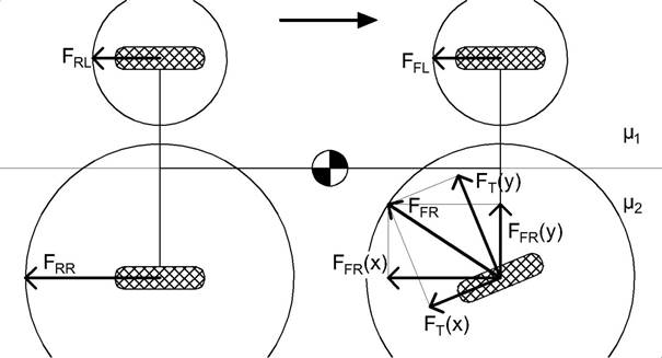
Fig. 2. Braking with an independent front-wheel
steering system
As mentioned
before, the advantage of the fully independent left and right steering system
is to maximize the use of the longitudinal grip of the wheels on the surface
with a lower friction coefficient. For a conventional steering linkage
solution, the wheel with less traction also transmits lateral forces, causing a
decrease in the longitudinal force maximum value, which intensifies the
undesirable car torque relevant to the gravity centre. In the presented case,
the steering wheel angle will be in the range of about 0-20°, given that, for
standardized tyres, in this range of tyre sideslip, an increase in the lateral
force up to its maximum occurs [1].
In fact, the maximum total force transmitted by the
wheel as a function of this force direction is not constant, as assumed above
(circle in Figs. 1-2); rather, in most cases, it has a shape that is more
similar to an ellipse than a circle (higher force FT(y)), as shown
on the graph, which actually increase the positive effect of the proposed
solution. The value of FFR in Figure 2 could be greater.
The forces presented in Figure 1 are twice as strong
at the vehicle’s right-hand side, while the friction coefficients are also
obviously 1:2 to each other. After the introduction of modifications shown in
Figure 2, the torque relative to the gravity centre disappears. The moment of forces
generated by the right-rear wheel and that emanating from the two left wheels
are balanced. Torque from the front-right wheel is zero because of the angle
(in line with the gravity centre). Therefore, it behaves in a way that is
theoretically perfectly, maintaining the desired vehicle position. In the case
of four-wheel independent steering, there is a possibility of changing the
proportion of forces counteracting the rotation between axes. Algorithms to
control this aspect should be similar to those implemented in traction control
systems. The proposed system should be integrated with other systems of the
car, especially the anti-lock braking. In real situations, the flexibility of
components, including tyres, should be taken into account. As a result of using
active independent steering, the toe angle can be constantly modified without
limitation. In emergency situation, this feature, together with skid steering,
can be used to safely stop the vehicle. This technique can also be used to
maintain control in the case of the failure of one or more of the actuators
responsible for wheel twisting, in which braking force is applied to individual
wheels [9]. Currently, steer-by-wire systems are in the phase of development,
including in relation to changing views, needs and limitations on the part of
the driver, for example [3]. In a car with four-wheel independent steering,
this is seems to be much more important issue, due to the car’s less intuitive
behaviour. This is not a problem in autonomous vehicles, where the proposed
system could bring significant benefits. Independent steering can be used to
automatically compensate for the bump and roll steering effects, which allow
for more freedom when shaping the geometry of the connecting rods.
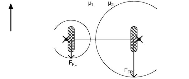
Fig. 3. Negative scrub radius
During cornering in a car with two independent,
actively steered wheels of the front axle, there is a limited possibility of
adjusting the position of the vehicle body’s centre of rotation in the
longitudinal direction with a suitable shaping of the sideslip angle at every
wheel, which results from setting two controlled wheels. In the case of
four-wheel steering, the centre of rotation can be chosen freely, with the only
limitation being the speed of steering and the maximum steering angle. The
proposed system can be combined with other systems allowing for the geometry of
the wheel to change while driving. Active independent steering can be used to
improve the behaviour of the car during manoeuvres at high speeds, while
providing profit due to the significant enlargement of autonomous parking
system limits. Systems with four-wheel steering offer, among other things,
every advantage of vehicles with rear-axle steering implemented in any method,
in particular, limiting the rotary movements of the body during cornering at
high speeds. Another important issue is the process of entering into a turn,
when the vehicle body starts to lean outside; as such, the steering angle of
every wheel could be properly set at every moment to obtain a response to the
road situation and vertical forces. In conventional steering, the linkage with
the mechanical stability of the structure usually remains. In the proposed
system, this aspect may cause some problems, but this should be considered
according to tyre grip characteristic, as well as the directional and
rotational stability.
4. CONCLUSION
Nowadays, in the era of the automation and
autonomization of transport processes, safety should be a priority
consideration. The obvious limitation, which results from the law of physics,
cannot be avoided, but can be shaped in a sophisticated way. According to a
number of practical problems connected with the proposed solution, the effects
resulting from independent steering can only be partially used in order to slightly
improve vehicle behaviour. As shown above, this could bring some benefits when
correctly controlled. Therefore, further numerical calculations and
experimental validations should be conducted.
References
1.
Abe Masato. 2015. Vehicle Handling Dynamics. Waltham:
Elsevier Ltd.
ISBN 978-0-08-100390-9.
2.
Lam Lun Tin, Huihuan Quian, Yangsheng Xu. 2010. Omnidirectional steering
interface and control for a four-wheel independent steering vehicle”. IEEE/ASME Transactions on Mechatronics, Vol.
15, No. 3: 329-338. ISSN: 1083-4435.
3.
Odenthal Dirk,
Tilman Bunte, Heinz-Dieter Heitzer, Christoph Eicker. 2002. “How to make steer-by-wire
feel like power steering.” In 15th
Triennial World Congress:
187-192, 2002, Barcelona, Spain.
4.
Prochowski Leon.
2008. Mechanika ruchu. [In Polish: Movement mechanics]. Warszawa:
Wydawnictwo Komunikacji i Łączności. ISBN 978-83-206-1701-6.
5.
Qi Ziming, Xu
Zhao, Kuang Ma, Matthew King, Wei-Chen Lee, Ji-Wei Lin, Shao-Min Lee.
2015. “4-wheel independent in-wheel-motor drive and independent steering
electric vehicle safety analysis method based on mass re-distribution
experiment”. In Proceedings of the
Sixth International Conference on Automation, Robotics and Applications:
22-27, 17-19 February 2015, Queenstown, New Zealand.
ISBN 978-1-4799-6467-3.
6.
Reimpell
Jörnsen, Jürgen Betzler. 2008.
Podwozia samochodów. Podstawy konstrukcji. [In Polish: Chassis. Fundamentals of design]. Warszawa: Wydawnictwo Komunikacji i Łączności. ISBN
978-83-206-1400-8.
7.
Reński Andrzej.
2011. Bezpieczeństwo czynne samochodu.
[In Polish: Active safety of a car]. Warszawa: Oficyna Wydawnicza
Politechniki Warszawskiej.
ISBN 978-83-7207-904-6.
8.
Układ stabilizacji toru jazdy ESP. Informator
techniczny Bosch. [In Polish: Electronic
Stability Program (ESP). Bosch Technical Information]. 2000. Warszawa: Wydawnictwo Komunikacji i Łączności. ISBN
83-206-1365-5.
9.
Wang Rongrong, Hui Jing, Chuan Hu, Mohammed Chadli, Fengjung Yan. 2016. “Robust H1 output-feedback yaw control for in-wheel motor driven electric
vehicles with differential steering”. Neurocomputing,
173: 676-684. ISSN: 0925-2312.
10.
Waizuddin Ahmed, Rawat Vaibhav, Yangsheng Xu. 2016. “An active steering system for road vehicles”. International Journal of Advances on Automotive and Technology,
Vol. 1, No. 1: 1-5. ISSN: 2536-4480.
Received
26.10.2016; accepted in revised form 10.01.2017
![]()
Scientific Journal of Silesian University of
Technology. Series Transport is licensed under a Creative Commons
Attribution 4.0 International License