Article citation information:
Jafernik, H. The test
programme concerning aircraft positioning and traffic monitoring – part II. Scientific Journal of Silesian University of Technology. Series
Transport. 2016, 93, 41-48. ISSN:
0209-3324. DOI: https://doi.org/10.20858/sjsutst.2016.93.5.
Henryk JAFERNIK[1]
THE TEST
PROGRAMME CONCERNING AIRCRAFT POSITIONING AND TRAFFIC MONITORING – PART II
Summary. This paper
presents the results of studies on the determination of an aircraft’s
trajectory and positioning accuracy. The PPP method was applied to determine
the aircraft’s position in kinematic mode for code observations in the GPS
system. Computations were executed in the “PPP_KINEMTIC” software, whose source
code was written using the Scilab 5.3.2 platform. The PPP_KINEMTIC software
allows for the latitude coordinate to be estimated with accuracy between 1 and
6 m, the longitude coordinate to be estimated with accuracy between 0.5 and 2.5
m, and the ellipsoidal height to be estimated with accuracy between 1 and 7 m.
The average value of the MRSE term equals 5 m with a magnitude between 1 and
8.5 m. In the paper, general libraries of the PPP_KINEMTIC application were
presented and the PPP method was characterized too.
Keywords: GPS,
PPP method, accuracy analysis, aircraft trajectory monitoring, safety, risk, threats, Global Navigation Satellite
System (GNSS)
1.
INTRODUCTION
The main aim
of the study was to test the functioning of a system for monitoring aircraft
and other vehicles after the installation of a new, modified software produced
by the Samset company. The most crucial element was to carefully check the
radio link and determine the exactitude, continuity, availability and
credibility of the system being developed. In the tests, the
aircraft’s trajectory was registered during a test flight and the material
collected was used to analyse the accuracy of this air traffic monitoring
system.
2.
ANALYSIS OF RESEARCH RESULTS ON
TECHNICAL CONDITIONS
Three points
spread evenly along flight trajectories (VirA, VirB, Base) functioned as
the Earth reference stations (Fig. 1). Stations VirA and VirB used in the
research were virtual points, whose observations were generated in the POZGEO-D
service of the ASG-EUPOS system, while station Base (Fig. 2) was a local physical
station placed near the runway at Mielec Airport, where a geodetic receiver,
Topcon HiPerPro, was placed. The data from all base stations were recorded in
one-second intervals.
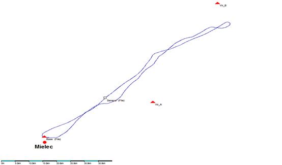
Fig. 1. Trajectory of the Seneca
Piper PA34-200T airplane and placement of the three base stations [2]
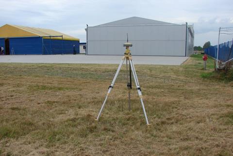
Fig. 2. Local reference station:
Base, located at Mielec Airport [4]
The exact
coordinates of the reference points (determined to the nearest centimetre) are
presented in Table 1.
Table 1.
Coordinates of the reference stations’
points used in the experiment
|
Point
number |
Latitude
(B) |
Longitude
(L) |
Height
(h) |
|
VirA |
50° 28’ 00”,00000 |
22° 00’ 00”,00000 |
200,000 |
|
VirB |
50° 52’ 00”,00000 |
22° 20’ 00”,00000 |
200,000 |
|
Base |
50° 19’ 36.58544” |
21° 27’ 02.76915” |
201.481 |
Three
autonomic OTF positions made it possible to determine the average error of
the average position for each second of the flight. The average errors
were calculated separately for each of the coordinates, i.e., B, L, h
(ellipsoidal height). To evaluate the accuracy of the calculations,
the following parameters were taken into account:
- the
average errors of individual geocentric components mx, my and mz (if necessary,
mB, mL and mh of the geodetic components),
- the
error in the receiver aerial position (understood as the error resulting from
the airplane’s position).
The values
of average errors of components (mx, my and mz) were appointed in
the geocentric system according to the following dependencies [8]:
 (1)
(1)
where:
![]() = average error of adjustment (standard deviation of
measurement)
= average error of adjustment (standard deviation of
measurement)
![]() (2)
(2)
![]() = number of
observations
= number of
observations
![]() = number of appointed
parameters
= number of appointed
parameters
![]() = correction to the pseudo-distance observed
= correction to the pseudo-distance observed
Values (![]() ,
, ![]() i
i ![]() ) are appointed in the geodetic system according to the
transformation [8]:
) are appointed in the geodetic system according to the
transformation [8]:
 (3)
(3)
where:
![]() = matrix of transformation from the geocentric system to the
geodetic system (coefficients in the matrix are dimensionless)
= matrix of transformation from the geocentric system to the
geodetic system (coefficients in the matrix are dimensionless)
 (4)
(4)
The received
values of the errors in geodetic coordinates B, L, h are presented in Figure 3.
The blue colour represents the average error of component B, the yellow colour
represents that of component L, and the red colour that of component h.
The average
errors of coordinates B, L, h for the reference position of a flying airplane
were approximately 2-3 cm for the horizontal coordinates and 4-6 cm for the
vertical coordinate. The results obtained for each second of the flight are
presented in Figure 3.
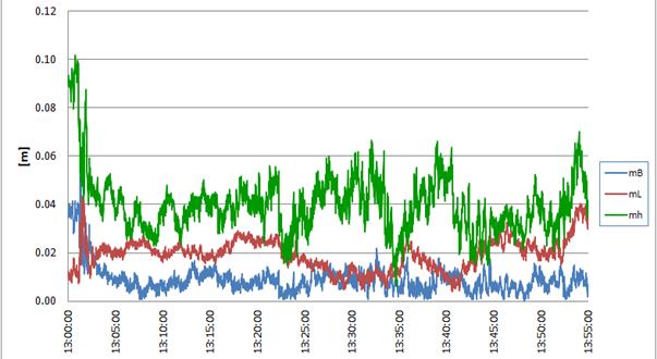
Fig. 3. Average errors of coordinates B, L, h for each
second of the flight
Having determined
the exact positions of the airplane (to the nearest centimetre) for each second
of the flight, it was possible to estimate the accuracy of the Samset system
installed on the board of the plane. During the tests, the GNSS receiver
(Novatel) worked in an autonomic mode and sent the position of the plane at
each second of the flight by radio through the UHF connection, using the radio
modems made by Satel company. The detailed data concerning the airplane flight
trajectory were registered on the server of a dispatch system.
The dispatch system was, for research purposes, installed in an object at
Mielec Airport, while the UHF aerial was installed at a mast next to the
object.
After
geodetic conversion of the coordinates into a common reference system, the coordinates
received were compared with the coordinates provided by the Samset company,
which were determined using the new version of the dispatch system software and
a mobile unit of the system installed on the plane board.
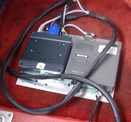
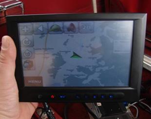
Fig. 4. Mobile unit of the system together
with the control panel installed on the plane board
While
comparing the data, it turned out that the data from the dispatch system
contain gaps caused by interference in the data reception from the plane. The
stability of data recording in the new version of the software is much better,
although minor inaccuracies occur, which is described in a later part of the
report.
The biggest
number of gaps was observed in the north-eastern part of the flight trajectory,
when the plane was the furthest from the dispatch system aerial. In the other
parts of the flight were few gaps, which usually lasted 1-2 s. The data
registered also contained a few gaps lasting from a few to a few dozen
seconds.
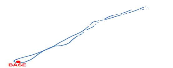
Fig. 5. Trajectory according to the Samset system
(the gaps can be seen in the north-eastern part of the trajectory)
A detailed
comparison showed that, for 3,301 s of the flight, 1,138 measurement epochs
were registered, i.e., 66%, while, for 2,163 epochs, there were no data
recorded concerning the position of the plane. The gaps in the recordings of
the plane position were mostly caused by the physical reach of the radio modem
of the mobile module installed on the plane board. This solution was temporary
and the radio aerial was inside the cabin. The additional parameter limiting
the availability of the plane position was that the plane flew at various
heights, which was connected with the test of the system coverage for various
cruising altitudes. During the experiments, for some measurement epochs,
the time was assigned incorrectly. It is particularly visible in the initial
phase of the flight, given that, later on, the situation becomes more
stable and the time incorrectly assigned to the epochs rarely occurs. The
incorrectly assigned time leads to the error in positioning of 40-60 m.
The accuracy
achieved is quite satisfactory and, for the flight being analysed, it is about
5-10 m for the horizontal coordinates and 10-15 metres for the height. The
graph comparing the system coordinates with the reference coordinates is
presented in the figures below.
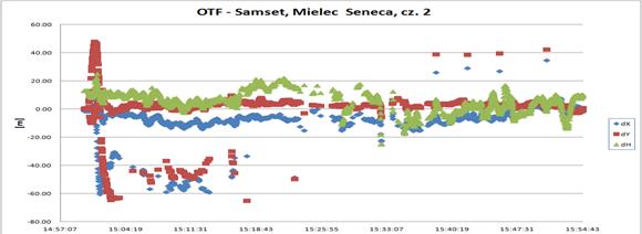
Fig. 6. Difference between the
reference position (OTF) and the system position
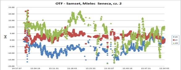
Fig. 7. Difference between the
reference position and the system position (enlarged)
The results
obtained show that the new software for the monitoring system is much more
stable, while the errors and shortcomings only rarely occur.
4. CONCLUSION
Summing up,
the research focused on checking the accuracy of positioning, the reach and the
workability of individual elements of the system (tests without DGPS, with DGPS
and with EGNOS from various airports). The radio modem’s UHF and the GSM
cellular network (GPRS) were used to transmit the data between an aircraft and
Earth, between an aircraft and an aircraft, and between an aircraft and a
vehicle. After an appropriate adaptation, the user of the system may use his or
her own transmission medium. At every stage of the tests, the revealed
errors and shortcomings of the individual elements of the system were eliminated.
Depending on
the method used, the accuracy achieved varied from about 0.5 to 5-7 m, while
the coverage varied from about 15-30 km for UHF between the vehicles and the
base station, and 40-80 km between the airplane and the base station. It is
possible to increase the coverage when the plane is used as a
retranslator. On-board equipment automatically registers the retranslation
of the signal for other elements within its reach.
Moreover, as
part of the project, flight tests on the EGNOS system were carried out, which
represented some of the first tests using EGNOS for aviation needs taking place
in our country.
The essence
of the research was not the monitoring of vehicles itself, but the possibility
of mutual coordination of activities in real time, in a limited area, in
difficult conditions and with many vehicles involved. The most important tasks
that the author tried to accomplish were to achieve the possibility of
operating the vehicles from both the stationary and mobile stations, as well as
the possibility of mutual retranslation of signals with the use of various data
transmission sources (GPRS, GPS, UHF). The important point here is that it is
possible to partially use the developed satellite and information technologies
in practical activities by various institutions. If we take into account the
fact that some airplanes have satellite equipment on their boards, the
adaptation of technologies for the needs of the system will be easier. It means
that, in our country, we already have the equipment that can be used at the first
stage of creating the system. There is a plan to equip other aircrafts with
on-board satellite receivers.
When we
compare the final results of the research with presently used solutions, with
regard to state official regulations (Global Air Navigation Plan for Systems
CNS/ATM-Doc. 9750), which treat the GNSS satellite navigation system as a key
element in communication, navigation and surveillance systems used for managing
the air traffic (CNS/ATM) and also as a foundation on which countries may
develop improved services for air navigation, we can see that the subject was
worth tackling and the research results are satisfactory. Many countries carry
out tests on the ADS-B (automatic dependent surveillance-broadcast) automatic
surveillance system. The on-board GPS receiver is used as a basic source of
information about the position and time within this system. The ADS-B network
was created and tested in Northern Europe as part of the Northern European
ADS-B Network project. According to the plans of the countries belonging to the
ADS-B Network, this system will soon partially replace the traditional radar
used to monitor air traffic. A crucial element in this kind of system is the
GNSS. Despite suggestions to do so from the ICAO, Poland does not take part in
these projects, which means that the author’s attempts to address this issue is
a novelty. Similar issues were dealt with during the research on the
system aimed at coordinating activities by the individual elements
participating in a potential rescue operation, including the surveillance of
the vehicles taking part in such an operation in the Mazury Region, which was
presented at the DESIW Mrągowo-Szczytno Conference, which took place from 24-26
October 2005. This research, however, ignored the aviation aspect, which is yet
another argument in favour of the legitimacy of the research undertaken by the
author. Furthermore, the idea of aircrafts’ monitoring systems using satellite
navigation systems fits perfectly with the idea of using GNSS in aviation in
both Europe and the rest of the world. Furthermore, one of the main tasks of
the GALILEO satellite navigation system, developed by the EU, is to support all
operations connected with the safety of EU member states and citizens. In Poland,
the economic situation is probably the obstacle to the fast and widespread
introduction of the surveillance system. On the other hand, the creation
of this system could be divided into stages and local management systems could
be introduced gradually. While they are being introduced, it will be possible
to guarantee safety and the effective exploitation of the system. In the
future, taking into account current knowledge, it will be possible to introduce
the theory and practical solutions presented in the paper to the developed
complex system for monitoring aircraft and land vehicles, as well as the system
for their management, which will use stationary or mobile stations created
according to original solutions and commonly available means.
The system presented
here has one more advantage: it is based on commonly available equipment,
meaning that, with only minor adjustments, it can be widely used without high
additional costs.
References
1.
Ciećko A., G. Grunwald, R. Kaźmierczak, S.
Oszczak, M. Grzegorzewski, J. Ćwiklak. 2011. „Wykorzystanie oprogramowania RTKLIB do badania dokładności systemu
EGNOS”. [In Polish: “The use of software RTKLIB to audit the accuracy of
EGNOS”]. Logistyka 6.
2.
Ciećko A., S. Oszczak, M. Grzegorzewski, J.
Ćwiklak. 2011. „Wyznaczenie pozycji
statku powietrznego oraz dokładności z wykorzystaniem systemu EGNOS w Polsce
wschodniej”. [In Polish: “Determination of the position of the aircraft and accuracy
with the use of EGNOS in eastern Poland”]. Logistyka
12.
3.
Ćwiklak J. 2010.
„Monitorowanie ruchu statków powietrznych i pojazdów służb porządku publicznego
z wykorzystaniem GNSS - cz. I. [In Polish: „Monitoring the movement of
aircraft and vehicles to law and order with the use of GNSS – part I]. Logistyka 6.
4.
Ćwiklak J., A. Ciećko, S. Oszczak, M.
Grzegorzewski, H. Jafernik. 2011. „Wykorzystanie systemu EGNOS na potrzeby
nawigacji lotniczej w Polsce wschodniej”. [In Polish: “The use of EGNOS for the purpose of air navigation services
in Eastern Poland”]. Problemy
eksploatacji 1: 57-64.
5.
Grunwald G., R. Kaźmierczak, S. Oszczak, A.
Ciećko, M. Grzegorzewski, J. Ćwiklak. 2011. „Wykorzystanie systemu EGNOS w nawigacji lotniczej w aspekcie uruchomienia
serwisu Safety-Of-Life”. [In Polish: „The use of EGNOS in air navigation
services in the context of commissioning Safety-Of-Life”]. ABID 3.
6.
Spits
J. “Total electron content reconstruction using triple frequency GNSS
signals”. 2011. Dissertation.
University de Liège, Belgium.
7.
IGS
Central Bureau. Available at: fttp://igscb.jpl.nasa.gov/igscb/product/.
Received 13.06.2016; accepted in revised form 20.09.2016
![]()
Scientific Journal of Silesian
University of Technology. Series Transport is licensed under a Creative
Commons Attribution 4.0 International License