Article citation information:
Fellner, A., Fellner R. Piechoczek E. RNAV GNSS flight validation
approach procedures for EPKT RWY27. Scientific
Journal of Silesian University of Technology. Series Transport. 2016, 93, 5-11. ISSN:
0209-3324. DOI:
https://doi.org/10.20858/sjsutst.2016.93.1.
Andrzej FELLNER[1], Eugeniusz PIECHOCZEK[2], Radosław FELLNER[3]
RNAV GNSS FLIGHT VALIDATION
APPROACH PROCEDURES FOR EPKT RWY27
Summary. The
purpose of this document is to present evidence of the work carried out as part
of the flight validation activities of the RNAV approach involving the instrument
flight procedures (IFPs), down to the localizer performance with vertical (LPV)
minima, for RWY27 at Katowice Airport (EPKT). The presented material
constitutes the second part of the “Preflight validation RNAV GNSS approach
procedures for EPKT in the EGNOS APV Mielec” project. The following issues were
addressed: flight validation conditions, list of performed approaches, flight
path analysis and pilot feedback.
Keywords:
flight validation, GNSS, aviation, RNAV, satellite navigation
1. INTRODUCTION
The purpose of this document is to present evidence
of the work carried out as part of the flight validation activities of the RNAV
approach involving the IFPs, down to the LPV minima, at EPKT for RWY27. The
presented material constitutes the second part of the “Preflight validation RNAV GNSS
approach procedures for EPKT in the EGNOS APV Mielec” project. The first part of research was described in a previous article
[3].
2. FLIGHT VALIDATION CONDITIONS
According to ICAO standards, the purpose of flight
validation is to determine whether a flight procedure is operationally
safe, practical and flyable for the target end user [8]. The following
guidelines were taken into consideration for conducting the flight validation
activities:
·
The validation was carried out in daylight hours under visual meteorological conditions (VMCs)
·
The final approach segment had to be flown one half of a scale down, at
least once
·
All segments of the approach were flown at least once (segments common to
the LNAV approaches were already flown during the LNAV validation flights)
·
The missed approach segment was flown
·
A test database containing the RNAV IFP was used
·
There was one pilot acting as the flight validation pilot (FVP)
and one observer assisting the FVP in the validation process observing the ‘out
of cockpit’ environment
·
The aircraft used during the flight validation had the appropriate
performance capabilities for which the IFP was designed.
The flight validation (FV) was conducted with a Piper Seneca II
aircraft. The aircraft is equipped with the appropriate RNAV (area
navigation) equipment for conducting
LPV guidance operations: a
Garmin GNS 430W connected with other required avionics (antenna, course
display indicator/vertical display indicator (CDI/VDI)). The complete set allows flying during all phases of flight
en route to the precision approaches down to the LPV minima. The IFP to be
validated, designed by Pildo and the Polish Air Navigation Services
Agency (PANSA), was coded inside a test
database produced by Jeppesen and Garmin. The pilots inserted the FV plan
inside the FMS-like Garmin device and conducted the trials in the relevant
navigation mode using the global positioning system/satellite-based
augmentation system (GPS/SBAS)
guidance. Guidance during the entire flight, including aircraft positioning,
was provided by the CDI/VDI fed by the GNS 430W.
In order to record
continuous data and monitor the EGNOS during the campaign, a flight data
recording and monitoring system was installed on the aircraft. The system (standalone
platform) included a U-blox Antaris 4 GPS/SBAS receiver. A Septentrio PolaRx2
GPS/SBAS receiver was installed on the ground during the flight validation. The
receiver was installed at EPKT. The main objective was to collect GPS L1/L2 and
EGNOS data, which were post-processing in order to allow for evaluating the
local performance of the system. The automatic reports regarding the
performance of the signal are included in the “EGNOS performance analysis and
SIS analysis” report. This report constitutes a brief overview of the performance
of EGNOS SIS (PRN 120) as observed at EPKT over a period of six hours from 14
March at 10:00 until 14 March at 16:20 with a Septentrio PolaRx 2/3 receiver.
(Note that, during this period, the EGNOS system was still under test
conditions and not yet fully deployed. Therefore, the results serve only as an
indication and cannot be used for the final validation.)
Before the flight trials, the local APV-1
availability in the area was simulated using a predictive receiver
autonomous integrity monitoring (RAIM) algorithm developed by PildoLabs. The
analysis was performed at the ARP, with the following conditions also
considered:
·
No digital terrain
model was used to simulate the local conditions of the area (useful in some environments
in order to take into account the masking caused by a mountainous environment)
·
The GPS almanac
was downloaded from the US Coast Guard Navigation Center website
·
The simulation was
carried out for a 12-hour data set (from 09:00 to 21:00), with samples every
five minutes
The obtained result concerns a 100% APV-1 availability at the threshold
coordinates. The estimated horizontal and vertical errors were also
estimated. This is presented in Figure 1.
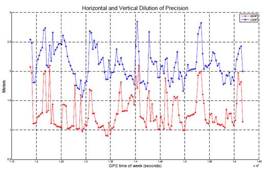
Fig. 1. Dilution of precision for
EPKT
These simulations ensured that the EGNOS would
enable an APV-1 level of service at EPKT during the entire day.
The data analysis focuses on the data recorded
during the flights. The following figures show the trajectories flown during
the approaches. The approaches are drawn in conjunction with the tested paths.
Table 1.
Flight validation plan: list of approaches
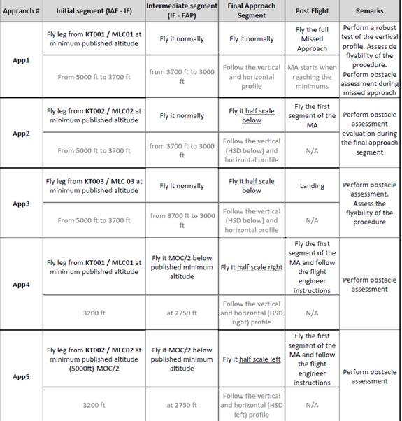
The following figures present the flight
trajectories of the demonstrations, together with the waypoints and runway
threshold. It can be seen how the aircraft successfully accomplished the
operations up to the obstacle clearance altitude/height (OCA/H) values, when
either a missed approach or a landing was conducted. In the profile views, the
following reference altitudes have been plotted:
·
5,000 ft = the
minimum altitude to fly the initial segments of both approaches,
·
1,235 ft = the CAT
A LPV minima (OCA) of the procedures,
·
991 ft = the
elevation of RWY 27 THR.
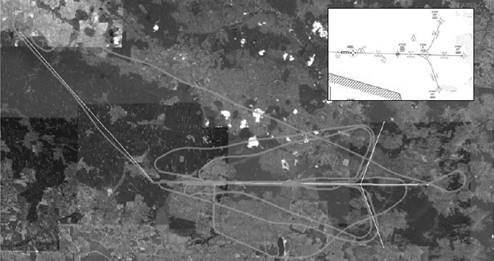
Fig. 2. Plan view of
the flight demonstrations
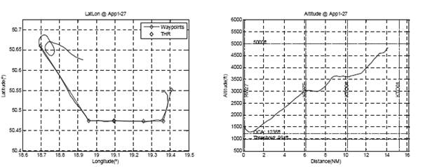
Fig. 3. Plan view of
the aircraft flight path and altitude profile
(note:
the profile graphs start after KT001 due to the flyby turn performed at this
waypoint)
The plan and profile views shown in
the above figures are consistent with the specified objectives in the flight
validation plan.
3.
FLIGHT DEVIATIONS
Establishing flight
deviations was necessary. To have a clearer picture of the deviations presented
to the pilot during the approaches, the horizontal and vertical deviations have
been computed with respect to the desired flight path. The results are
presented in the figures in this section. The distances along the vertical axis
represent the horizontal or vertical flight technical error (FTE) in metres.
The FTE is provided as guidance information to the pilot during the flight,
while the NSE and TSE can only be determined using truth references after
post-processing the data. Figures located on the left show the deviations of
the aircraft during the intermediate and final approach segments, while the
figures located on the right side zoom in on the deviations during the FAS. The
full-scale deflection (FSD) of the CDI/VDI is also plotted in the figures (cyan
colour) when contained in the figure limits, in both the horizontal and the
vertical domains. These curves indicate the value of the deviations that the
aircraft would have had with respect to the approach path, provided the CDI/VDI
needles had been totally deflected. The curves have been calculated using
in-house developed tools, in accordance with [2]. As can be seen, the FSDs are
not constant and change between being linear and angular along the approach,
following the requirements laid down in the minimum operational performance specifications
(MOPS).
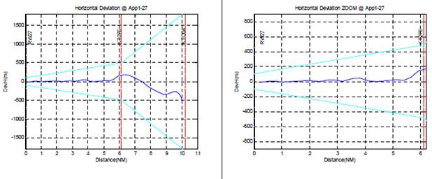
Fig. 4. Horizontal and
vertical deviations
The project considered pilot
feedback obtained using standard qualitative questionnaires about the
flyability of the approaches flown, as included in the ICAO Doc 9906.
Assessment of the proposed procedure followed the project’s methodology.
4. CONCLUSION
The LPV flight procedures
for RWY27 provide tangible operational benefits for airport operators in cases
of an inactive instrument landing system. The EGNOS system was capable of
providing excellent aircraft guidance, which was appreciated by the pilots. The
main outcomes of the validation of the new GNSS procedure are as follows:
·
The EGNOS
availability performance APV-I was fully achieved during all the approaches
·
The coding of the
procedure for SBAS is satisfactory
·
The horizontal and
vertical sensibility of the CDI was successfully tested
·
The procedure is
safe from the obstacle clearance point of view (it has been flown half scale
down the nominal glide path without identifying potential obstacles)
·
No significant
obstacles were found when overflying the surroundings of the airport either
·
The flyability of
the procedure was correct
The ground and flight validations were
performed successfully. The procedure is published in the AIP of Poland.
References
1.
APV
SBAS Approach: Concept of Operations 1.0. 28/01/2009.
2.
DO-229D.
2006. Minimum Operational Performance
Standards for Global Positioning System/Wide Area Augmentation System Airborne
Equipment. Washington: Radio Technical Commission for Aeronautics.
3.
Fellner Andrzej, Radosław Fellner, Eugeniusz Piechoczek.
2015. „Pre-flight validation RNAV GNSS
approach procedures for EPKT in “EGNOS APV Mielec project” “. Scientific Journal of Silesian University of
Technology. Series Transport. 2016, 90,
37-46. ISSN: 0209-3324. DOI: https://doi.org/10.20858/sjsutst.2016.90.4.
4.
MIELEC_CA
MIELEC Consortium Agreement 1.0.
5.
MIELEC
D3 GPS NPA and APV-I Procedure Design 2.0.
6.
ICAO.
2006. Doc 8168 Procedures for Air
Navigation Services Aircraft Operations. Volume II: Construction of Visual and
Instrument Flight Procedures. Montreal: ICAO.
7.
TechPro
MIELEC Technical Proposal 1.0.
8.
ICAO.
2012. Doc 9906 Quality Assurance Manual for Flight Procedure Design. Volume 5: Flight
Validation of Instrument Flight Procedures. Montreal: ICAO.
Received
11.08.2016; accepted in revised form 25.10.2016
![]()
Scientific Journal of Silesian University of
Technology. Series Transport is licensed under a Creative Commons Attribution
4.0 International License