Article citation information:
Vinogradov
B., Ostashko I. Substantiation of key parameters of a centrifugal mill intended
for grinding solid residue from the pyrolysis of used automobile tyres. Scientific Journal of Silesian University
of Technology. Series Transport. 2016, 91,
133-141. ISSN: 0209-3324.
DOI: 10.20858/sjsutst.2016.91.14.
Igor OSTASHKO[1],
Boris VINOGRADOV[2]
SUBSTANTIATION OF KEY
PARAMETERS OF A CENTRIFUGAL MILL INTENDED FOR GRINDING SOLID RESIDUE FROM THE PYROLYSIS
OF USED AUTOMOBILE TYRES
Summary. The study presents the results of an investigation
into centrifugal mills with an energy-saving working body. Rational geometric
parameters of the working body of the centrifugal mill, which grinds the
solid residue from the pyrolysis of used tyres, have been justified on the
criterion of the lowest specific energy consumption during the grinding
process. A method to determine the dependence of the in-grinding power
consumption on the basic parameters of the working body has been developed, while
an analytical expression to determine the power consumption for grinding
the solid residue from the pyrolysis of used tyres has been obtained. It has
been found that the power consumption in the grinding process linearly depends
on the rotational speed of the working body, which is to the 0.3 power on the
average size of solid particles.
Keywords: centrifugal
mill, working body, power consumption, solid residue from pyrolysis.
1. INTRODUCTION
Centrifugal
mills have been widely used in many industries for grinding various abrasives
[1]. The main structural element in most centrifugal mills is a working body
containing beater elements in the form of blades and baffles. The grinding
process in these mills is performed through a high speed transferred to the material,
which results in significant power consumption.
The aim of
the article is to study the main parameters of a centrifugal mill for fine
grinding of the solid residue from the pyrolysis of waste tyres with the lowest
specific power consumption.
2. PRESENTING MAIN
MATERIAL
After a careful study of various
designs of centrifugal mills and preliminary laboratory tests, a new design of
the centrifugal mill has been developed and presented (Fig. 1 [2]), which
allows for grinding granular materials, such as the solid residue from used tyre
pyrolysis, with the lowest specific power consumption.
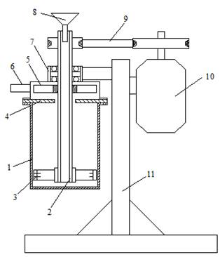
Fig. 1. Centrifugal mill: 1 -
grinding chamber; 2 - hollow shaft; 3 - working body; 4 – ring for
classification; 5 - impeller; 6 - outlet; 7 - bearing assembly; 8 - hopper;
9 - belt drive; 10 - motor; 11 - support column.
The design feature of the proposed
mill is the shape of the working body and the method of discharging the
finished grade, which can significantly reduce the specific energy consumption
during the grinding process, thereby facilitating the classification of the
ground material directly in the mill.
Preliminary studies were carried out
on the mill, in which the grinding chamber was shaped as a regular
cylinder with a diameter of 0.3 m. In the course of the studies, the rational
design and technological parameters of the mill were determined in terms of
minimum specific energy consumption during the grinding process [3]. It has
been found that: a grinding chamber’s effective filling level is 25-30% of its
volume; an active length of the working body is shifted to its periphery by as
much as 15-25% of its volume, depending on the rotational speed; the gap
between the beaters is between 3 and 5 mm; and the specific energy consumption
for grinding the class of less than 43 µ with a two-beater working body is 57
kWh / t, while it is 21 kWh / t for a four-beater working body.
The study of the granulometric
composition of the ground material (Fig. 2) shows that an increase in the
number of beaters from two to four results in increased efficiency, while specific
energy consumption is decreased by 180% at the same time. However, a further
increase in the number of beaters increases the specific energy consumption
with no change in output. This can be explained by the fact that the
two-beater working body does not cover the entire area of intense grinding,
while the increased number of beaters reaches beyond this area.
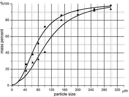
Fig. 2. Granulometric composition of
solid pyrolysis residue milled for 1 min by working bodies with different
numbers of beaters: 1 - four beaters; 2 - two beaters.
Strength calculations have confirmed
the advisability of the closed-type
working body design (Fig. 3). This type of working body design allows for grinding
due to impact and friction. In this case, larger particles, whose size > 100
µ, are mostly destructed by their impact interaction with the working body in
the peripheral area, while particles, whose size < 100 µ, are mainly
destructed due to friction forces, which arise from the material interaction
with the grinding chamber walls and the working body.
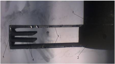
Fig. 3. Working body of the new
design: 1 - hollow shaft; 2 - working body mount; 3 - beaters; 4 – beater in
the area of intensive milling; 5 - end beater.
In an idling mode, i.e., in the
absence of material feed, the working body of this design consumes the power
determined by formula in [3]:
![]() , (1)
, (1)
where ρm is the
density of the medium that interacts with the working body (kg / m3),
ξ is the drag coefficient, A0 is a parameter that takes
into account the geometry of the working body,
(k
ωw) is the relative angular velocity of the working
body, ωw is the angular velocity of the working body,
and k is the slip coefficient, which
characterizes the speed of the working body’s interaction with the medium. In
turn,
![]() ,
,
where ωair is the angular
velocity of the air.
The unknown terms in Equation (1)
are ξ, k. To determine the
terms, two separate cases were considered: when the mill was operated with either
the grinding chamber removed or the grinding chamber mounted, no material
charged. The power consumptions N1
and N2 can, respectively, be
determined based on the following equations:
![]() (2)
(2)
![]() (3)
(3)
where N1, N2,
k1, k2 are the power consumptions and coefficients of slipping with the removed
and mounted grinding chamber, respectively.
The working body power consumption N1, N, at different rotational speeds,
and the air angular velocity ωair
were experimentally determined with the grinding chamber removed with the use
of a cup anemometer.
To determine the N1, N2 power consumptions of the working
body, the total power consumption was first measured using the following
formula: NΣm = Nlost + Ni, where Nlost
is the power lost in the mill’s electromechanical transmission with the working
body removed, and i is the experiment
number 1 or 2. Then, the power consumed by the working body was be determined
by the formula: Ni = NΣm - Nlost.
Fig. 4 and Fig. 5 show the
dependence of the angular velocity of the air and working body power
consumption on the rotational speed. Fig. 6 shows the experimental dependence
of the working body power consumption on the rotational speed when the
grinding chamber is loaded with solid residue of tyre pyrolysis with average
particle size dav = 43 µ.
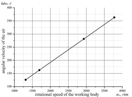
Fig. 4. Angular velocity of the air
flow: ωair – angular
velocity of the air;
nw
– rotational speed of the working body.
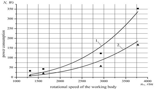
Fig. 5. Curves of power consumed by
the working body: 1 - with the grinding chamber removed; 2- with the grinding
chamber mounted.
By knowing the angular velocity ωair0 of
the air during the rotation of the working body with the grinding camera
removed, along with the power consumption, we can determine the relative
angular velocity k1 ∙ ωw
= ωw-ωair0 and drag coefficient ξ. Assuming that the drag coefficient is the same whether the
camera is removed or mounted, we calculate the relative angular velocity of the rotor
with the chamber mounted as follows: k2
∙ ωr = ωr – ωac (ωac is the angular
velocity of the air during the working body rotation in the grinding chamber).
The experimental data show that the
air velocity is directly proportional to the working body rotational speed
(Fig. 4), while the slip coefficients are k1
= 0.92, k2
= 0.83, and the drag coefficient is ξ
= 12.6. The experimental results also confirm the adequacy of Equation (1), namely,
that the power consumed by the test working body, which operates in an empty
chamber, depends on the rotational speed taken to the third power (Fig. 5).
Fig. 6 shows an experimental
dependence of wattage consumed by the working body, which operates with the
grinding chamber loaded. The material taken was the solid residue from the
pyrolysis of used tyres, with an average particle diameter of dav =
43µm. Meanwhile, the degree of filling in the grinding camera was Vm / Vc = 0.27 (Vm, Vc represent the volumes of
the material and the chamber, respectively) and the material bulk density was
445 kg / m3.
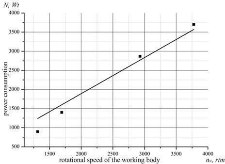
Fig. 6. Dependence of power
consumption on the rotational speed of the working body during the grinding
process.
In contrast to an empty chamber,
where air is the medium, the power consumption in the loaded grinding chamber is
linearly dependent on the rotational speed of the working body. This can be
explained by the fact that, during the grinding process, the material
influenced by centrifugal forces is unevenly distributed throughout the inside
of the grinding chamber and concentrated along its walls. This reduces an
active area of the working body, which results in further changes in the
distribution of the forces of resistance. Based on the analysis of Equation (1)
and the experimental data (Fig. 6), a conclusion can be made that the dependence
of A0 (the parameter
characterizing the size of an active part of the working body) on the
rotational speed takes the following form:
![]() , (4)
, (4)
where ν
= 1.72 is the coefficient, which takes into account the decrease in an active
part of the working body.
To determine the power consumption,
we substitute the values of ν and assume that coefficients ξ are
equal for either an empty or a loaded grinding chamber, while an average
diameter of solid particles dav
= 43 µm. In turn, Expression (1) takes the following form:
![]() . (5)
. (5)
Fig. 7 shows the experimental
dependence of the power consumption on the average material particle diameter
at an angular velocity of 389 s-1. Increased power consumption in
relation to the increase in the average particle diameter may be explained by
an increase in the relative angular velocity of the interaction between
the working body and the medium.
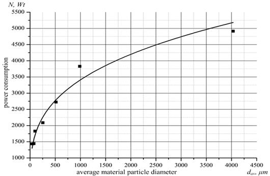
Fig. 7. Power consumption change
with average particle diameters at an angular velocity of 389 s-1.
When working with the material feed,
slip coefficient k2
undergoes changes due to the reduction in the rotational speed of the
medium; the drag coefficient ξ
is also subject to a change, since the parameters of the medium have
changed. It is therefore necessary to consider the product of the two
coefficients as a function of the average material particle diameter dav.
![]()
Experimental dependence of power consumption on the average diameter of
particles in the grinding chamber (Fig. 7) can be approximated with a
dispersion of R = 0.97, according to the following
function:
![]() . (7)
. (7)
By equating the power consumptions defined by Formulas (5) and (7), we
obtain:
![]() . (8)
. (8)
Thus, the general formula, which will determine the wattage consumption
for grinding the solid residue from the pyrolysis in the centrifugal mill,
takes the following form:
![]() . (9)
. (9)
3. CONCLUSIONS
1. The proposed design parameters of the working
body and the mill as a whole will provide the minimum specific power
consumption during the material grinding.
2. The formula obtained by the authors can be
used to determine the power consumed by the centrifugal mill’s working
body for grinding the solid residue from the pyrolysis of used tyres.
3. It has been found that, during the grinding
process, the power consumption linearly depends on the rotational speed of the
working body and is proportional to an average size of solid particles, which
are taken to the 0.3 power.
4. The method developed by the authors allows for
obtaining a dependence of power consumption by the centrifugal mill’s working
body on its basic parameters, as well as the parameters of the material to
be ground.
References
1.
Бардовский
А. Д., Л. А.
Летин, Н. М.
Кряжев, И. И.
Дерба, Е. В.
Пухучкин. 2002. Определение
параметров
центробежной
мельницы
роторно-струйного
измельчения
при помоле
отходов
карбонатного
сырья. Горный
информационно-аналитический
бюллетень 1: 204-206.
Мoscow: МГГУ. [In Russia: Bardovskiy A. D., L. A. Letin,
N. M. Kryazhev, I. I. Derba, E.V. Pukhuchkin. 2002. „Defining the parameters
of a centrifugal rotor-jet mill when milling waste carbonate raw materials”. Mining Informational
and Analytical Bulletin 1: 204-206.
Moscow: Moscow State Humanities University.]
2.
Виноградов
Б. В., И. О.
Осташко. 2009. Об
энергетических
характеристиках
центробежных
мельниц с
S-образным
рабочим органом.
Вісник
НТУ „ХПІ” 25: 164-169. [In Ukraine: Vinogradov B. V.,
I. O. Ostashko. 2009. „On the energy performance of centrifugal mills with an
S-shaped working body”. Bulletin of the Kharkiv Polytechnic
University 25: 164-169. Kharkiv: Kharkiv Polytechnic University].
3.
Виноградов
Б. В., И. А.
Осташко, В. И.
Емельяненко.
2009. „Измельчение
твердых
остатков
процесса
пролиза
изношенных
автомобильных
шин в
центробежной
мельнице”. Вопросы
химии и
химической
технологии 2:
159-161. [In Ukraine:
Vinogradov B. V., I. O. Ostashko, V. I. Emel'yanenko.
„Shredding of solid residue pyrolysis of used tyres in a centrifugal mill”. Issues of
Chemistry and Chemical Technology 2: 159-161. Dnepropetrovsk: Ukrainian
State University of Chemical Technology].
4.
PL
216901 B1. Układ mechaniczny
strojony w sposób płynny. [In Polish: Smoothly
tuned mechanical system.]. Homišin Jaroslav. 2014. Warsaw: Polish Patent
Office.
5.
Grega
Robert, Jozef Krajňák. 2012. „The
pneumatic dual-mass flywheel”. Scientific Journal of Silesian University of
Technology. Series Transport 76: 19-24.
ISSN: 0209-3324.
6.
Homišin
J., P. Kaššay, M. Urbanský. 2011. „High-flexibility characteristics of pneumatic flexible shaft couplings”. Pneumatyka
79(2): 26-29. ISSN 1426-6644.
7.
Mantič M., J. Kuľka, J. Krajňák, M. Kopas, M. Schneider. 2015. „Influence of selected digitization methods on final
accuracy of a 3D model”. Production Management and Engineering Sciences: 475-480. Proceedings
of the International Conference on Engineering Science and Production
Management (ESPM 2015). Tatranská Štrba, High Tatras Mountains, Slovakia, 16th-17th
April 2015. Edited by Majerník M., D. Naqib, B. Martin.
Boca Raton, FL: CRC Press, Taylor & Francis Group. ISBN: 978-1-138-02856-2.
Received 11.12.2015; accepted in revised form 02.05.2016
![]()
Scientific Journal of Silesian University of
Technology. Series Transport is licensed under a Creative Commons
Attribution 4.0 International License