Article citation information:
Medvecká-Beňová S. Influence of the face width and length of contact on
teeth deformation and teeth stiffness. Scientific
Journal of Silesian University of Technology. Series Transport. 2016, 91, 99-106. ISSN: 0209-3324. DOI: 10.20858/sjsutst.2016.91.10.
Silvia MEDVECKÁ-BEŇOVÁ[1]
INFLUENCE OF THE FACE WIDTH
AND LENGTH OF CONTACT ON TEETH DEFORMATION AND STIFFNESS
Summary. Gear teeth are deformed due to
load. Recently, given the increasingly evolving computer technology, supported
by the available literature, we have modern numerical methods at our disposal,
such as the finite element method (FEM), which serves as one of the methods for
the determination of teeth deformation in the gearing. This paper mainly deals
with deformation distribution across the teeth’s face width in relation to the load
width of the teeth when meshing occurs. The solution for teeth deformation of
spur gears is provided by the FEM.
Keywords: spur gear, deformation of teeth, face width, finite
element method, stiffness
1. INTRODUCTION
The
theoretical determination of teeth deformation in involute gears is difficult
because the teeth profile consists of an involute and smooth filet. Previous
experimental procedures were based on the static deformation measurements of
the gearing’s loaded constant force or the seismic measurement deviations when
turns are carried out. However, such procedures require the construction of a
suitable model and the use of appropriate machinery, given the limited value of
deformation quality measurement technology. The FEM, therefore, is preferable
in terms of solving the matter in question, given that it is one of the most
widely used numerical methods. Teeth deformation in spur gears is not consistent
for all examined gear teeth. Such deformation depends on the shape of the
teeth and, in turn, the basic parameters of the gearing, as well as the shape
and construction of the body wheel and the wheel load. This paper mainly deals
with teeth deformation with regard to the face width, with the FEM presented as
the solution to this problem.
2. DEFORMATION AND STIFFNESS IN THE TEETH OF
SPUR GEAR
As previously stated, the FEM is a solution
for the deformation of teeth when meshing occurs. We will focus on the value of
the total deformation in the direction of action forces (Fig. 1). To determine
the deformation of the gearing under a load, it is necessary to be aware of the apportionment
of the load on each gearing pair when two pairs mesh. Firstly, let us consider
the simplest, ideal load apportionment, which is when two pairs meshing and the load
is divided by half for each pair of teeth involved in the meshing. Exercises to
calculate the gearing strength, shafts, gear wheels etc. involve a combined
load, which is replaced by lonely forces (Fig. 2). In our case, we will examine
the problematic in hand with regard to deformation in the width of the teeth.

Fig. 1. Teeth deformation of teeth
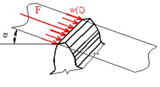
Fig. 2. Explanation of the load across the
width of a single force
One of the ways to calculate teeth
stiffness is by analysing the total gearing deformation as determined by the FEM.
In general, the resulting stiffness c is defined by Equation (1):
![]() ,
[N/mm.μm] (1)
,
[N/mm.μm] (1)
where w is the load across the width of the
teeth [N/mm], while δ is the resulting deformation [μm].
3. FEM SOLUTION FOR TEETH DEFORMATION AND STIFFNESS
After carrying out an analysis of teeth
deformation in the spur gear, in order to evaluate the 3D approach to the FEM,
it was found that deformation and stiffness were not constant across the width
of the teeth, but change. For the spur gear model used in this example, the
number of teeth z=19, the module of teeth m=1mm, the load w=25N/mm (F=500N) and
the gearing width b=20mm. Fig. 3 shows the course of the teeth deformation
and stiffness, when the spur gear is examined, if the width of the
teeth is consistent with the load width. The load is applied as shown in Fig. 1.
Under the influence of the free end of the teeth, but without any support
effect, there is a change to the beginning and the end of the meshing, while
the deformation of teeth expands and the stiffness of teeth reduces.
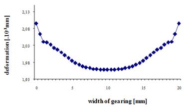
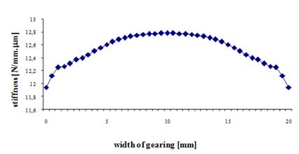
Fig. 3. Teeth deformation and stiffness when
the gearing width is consistent with the load width
In practice, we encounter cases
where the load width is less than the gearing width. Therefore, let us consider
the case where the gearing width gearing remains unchanged (b=20mm), while the
load width is reduced on each side, firstly, by 0.5mm (Fig. 4a) and, secondly,
by about 2.5mm (Fig. 4b).
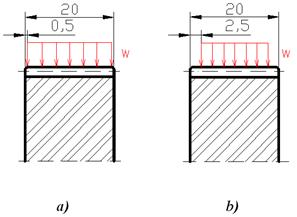
Fig. 4. Load width
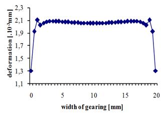
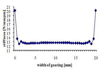
Fig. 5. Teeth deformation and stiffness when the
gearing width is not consistent with the load width, as shown in Fig. 4a.
Fig. 5 shows the course of the teeth
deformation and stiffness in relation to Fig. 4a. This concerns a spur gear model
where the number of teeth z=19, the module of the teeth m=1mm, the load w=26.31579N/mm
(F=500N), the gearing width b=20mm and the load width bw=19mm.
Fig. 6 shows the course of the teeth
deformation and stiffness in relation to Fig. 4b. It concerns a spur gear model
where the number of teeth z=19, the module of teeth m=1mm, the load w=33.33N/mm
(F=500N), the gearing width b=20mm and the load width bw=15mm.
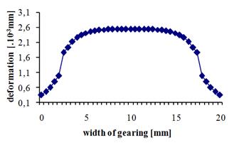
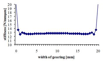
Fig. 6. Teeth deformation and stiffness when the
gearing width is not consistent with the load width, as shown in Fig. 4b
According to Fig. 5 and Fig. 6, if
the load width is less than the gearing width, the deformation at the edges of
the meshing incurs a sharp drop, while the stiffness experiences a sharp
increase.
When the course of teeth deformation
occurs in which the load width is equal to or less than the gearing width,
we can also monitor the effectiveness in addressing teeth deformation by use of
the 3D FEM (Fig. 7). When dark red is displayed, this means that the maximum
deformation of the teeth along the load width is limited.
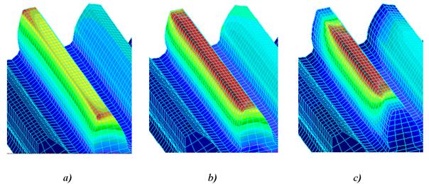
Fig. 7. Teeth deformation solution using the FEM:
a) where the gearing width is consistent with the load width; b) where the
gearing width is not consistent with the load width, as shown in Fig. 4a; and c)
where the gearing width is not consistent with the load width, as shown in Fig.
4b.
It should also be understood that
the course of deformation and stiffness across the width of the teeth,
when determined at various characteristic points on a line of action, will be
different. This is demonstrated in Fig. 8, which concerns a spur gear model where
the number of teeth z=19, the module of teeth m=1mm, the load w=33.33N/mm
(F=500N), the gearing width b=20mm and the load width bw=b=20mm.
Fig. 8. Teeth stiffness at the characteristic
points of contact
The characteristic points of contact
are defined in Fig. 9. Points A and E are the so-called external or end points along
the AE line of action. Points B and D are the so-called end points of lonely
meshing. Point C is a central contact point.
Fig. 9. Characteristic points of
contact in the spur gear
It can be seen that teeth stiffness at
the characteristic points under the same conditions change.
4. CONCLUSION
It is
possible to demonstrate, with great accuracy, teeth deformation along the width
of the load on the examined gear teeth by using the FEM. The findings in relation to this deformation
may be used to determine the stiffness of the teeth. Periodic changes in
stiffness when teeth mesh are caused by changes in the number of pairs of teeth,
which also mesh in order to create a significant noise impact on the teeth.
References
1.
Alfonso Fernandez del Rincon, Fernando Viadero, M. Iglesias, Pablo García,
A. de-Juan, Ramon . Sancibrian.
2013. „A model for the study of meshing stiffness in spur gear transmissions.” Mechanism
and Machine Theory 61: 30-58.
ISSN: 0094-114X.
2.
Medvecká-Beňová S. 2011. „Deformácia a tuhosť čelného ozubenia“. [In
Slovak: “Spur deformation and stiffness]. Strojárstvo
15(12): 8-9. ISSN: 1335-2938.
3.
Medvecká-Beňová S., P. Frankovský, R. Grega. 2015. „Influence gearing
parameters on the tooth deformation of spur gears“. Applied Mechanics and Materials 816: 27-30. ISSN: 1660-9336.
4.
Satiepka M., V. Dekýš, P. Pastorek. 2014. „Using active thermography and
lock-in method with ultrasound excitation for detection of material defects“. Scientific Journal of Silesian University of
Technology. Series Transport 84: 119-124.
ISSN: 0209-3324.
This paper
was written within the framework of the following Grant Project VEGA:
„1/0688/12 – Research and application of universal regulation system in order to
master the source of mechanical systems excitation”.
Received 08.11.2015;
accepted in revised form 29.03.2016
![]()
Scientific Journal of Silesian University of
Technology. Series Transport is licensed under a Creative Commons Attribution
4.0 International License